Seite wird geladen ...

BETRIEBSANLEITUNG
UE45-3S1
Sicherheitsrelais
de
SICK AG • Erwin-Sick-Straße 1
D-79183 Waldkirch • www.sick.com
8009662/10DH/2018-08-02 • REIPA/XX
Printed in Germany (2018-08) • Alle Rechte
vorbehalten • Irrtümer und Änderungen vorbehalten
1 Geltungsbereich
Diese Betriebsanleitung ist gültig für die Sicherheits-
relais UE45-3S1 mit dem folgenden Typenschild-
Eintrag im Feld Operating Instructions: 8009662
Das Herstellungsdatum des Geräts finden Sie auf dem
Typenschild im Feld Date Code im Format jjwwxxxx (jj =
Jahr, ww = Kalenderwoche, xxxx = Seriennummer).
Dieses Dokument ist ein Originaldokument.
2 Zur Sicherheit
Dieses Kapitel dient Ihrer Sicherheit und der Sicherheit
der Anlagenbediener.
> Bitte lesen Sie dieses Kapitel sorgfältig, bevor Sie
mit dem UE45-3S1 oder der durch das UE45-3S1
geschützten Maschine arbeiten.
2.1 Befähigte Personen
Das Sicherheitsrelais UE45-3S1 darf nur von befähig-
ten Personen montiert, installiert, in Betrieb genom-
men und geprüft werden.
Befähigt ist, wer …
• über eine geeignete technische Ausbildung verfügt
und
• vom Maschinenbetreiber in der Bedienung und den
gültigen Sicherheitsrichtlinien unterwiesen wurde
und
• Zugriff auf die Betriebsanleitung des Sicherheits-
relais UE45-3S1 und diese gelesen und zur Kenntnis
genommen hat.
2.2 Verwendungsbereiche des Geräts
Das Sicherheitsrelais UE45-3S1 ist einsetzbar:
• gemäß EN ISO 13 849-1 bis PL e und Kategorie 4
• gemäß EN 62 061 bis SILCL3
Die tatsächlich erreichte Kategorie hängt von der
Außenbeschaltung, der Ausführung der Verdrahtung,
der Wahl der Befehlsgeber und deren Anordnung an
der Maschine ab.
Das Sicherheitsrelais UE45-3S1 wurde nach UL 508
getestet.
Über die kontaktbehafteten Schaltausgänge des
Sicherheitsrelais können die zugehörigen Aktoren der
Maschine oder Anlage sicher abgeschaltet werden.
Das Sicherheitsrelais UE45-3S1 dient ausschließlich
zum Gebrauch an potenzialfreien Sicherheitssensoren,
wie z. B.:
• Not-Halt-Taster (EN ISO 13 850): ein-, zweikanalig
• Sicherheitsverriegelungen (EN 1088): einkanalig,
zweikanalig
2.3 Bestimmungsgemäße Verwendung
Das Sicherheitsrelais UE45-3S1 darf nur im Sinne von Ab-
schnitt 2.2 „Verwendungsbereiche des Geräts“ verwendet
werden.
Es darf nur von befähigten Personen und nur an der Maschi-
ne verwendet werden, an der es gemäß der Betriebsanlei-
tung von einer befähigten Person montiert und erstmals in
Betrieb genommen wurde. Bei jeder anderen Verwendung
sowie bei Veränderungen am Gerät – auch im Rahmen von
Montage und Installation – verfällt jeglicher Gewährleis-
tungsanspruch gegenüber der SICK AG.
2.4 Allgemeine Sicherheitshinweise und
Schutzmaßnahmen
a
Beachten Sie die Sicherheitshinweise und
Schutzmaßnahmen!
Beachten Sie die nachfolgenden Punkte, um die
bestimmungsgemäße Verwendung des Sicherheits-
relais UE45-3S1 zu gewährleisten.
• Beachten Sie bei Montage, Installation und An-
wendung des Sicherheitsrelais die in Ihrem Land
gültigen Normen und Richtlinien.
• Für Einbau und Verwendung des Sicherheits-
relais sowie für die Inbetriebnahme und wieder-
kehrende technische Überprüfung gelten die
nationalen/internationalen Rechtsvorschriften,
insbesondere:
– die Maschinenrichtlinie
– die Arbeitsmittelbenutzungsrichtlinie
– die EMV-Richtlinie
– die Unfallverhütungsvorschriften und Sicher-
heitsregeln
• Hersteller und Betr
eiber der Maschine, an der ein
Sicherheitsrelais verwendet wird, müssen alle
geltenden Sicherheitsvorschriften/-regeln in
eigener Verantwortung einhalten.
• Die Prüfungen sind von befähigten Per
sonen bzw.
von eigens hierzu befugten und beauftragten
Personen durchzuführen und in jederzeit von
Dritten nachvollziehbarer Weise zu dokumen-
tieren.
• Die Betriebsanleitung ist dem Bediener der Ma-
schine, an der das UE45-3S1
verwendet wird, zur
Verfügung zu stellen.
• Der Maschinenbediener ist durch befähigte Per-
sonen einzuweisen und zum Lesen der Betriebs-
anleitung anzuhalten.
3 Produktbeschreibung
3.1 Aufbau und Arbeitsweise des Geräts
Die Eingänge der Sicherheitsrelais UE45-3S1 sind für den
Anschluss der im Abschnitt 2.2 „Verwendungsbereiche des
Geräts“ aufgeführten Sicherheitssensoren vorbereitet. Zwei
separate Eingangskreise steuern die internen Relais. Die
Freigabestrompfade sowie der rückfallverzögerte Strompfad
sind als sichere Ausgänge ausgeführt.
3.2 Gerätefunktionen
Ein Öffnen der Eingangskreise bewirkt ein sofortiges Öffnen
zweier Freigabestrompfade und ein zeitverzögertes Öffnen
des dritten Strompfades. Die Zeitverzögerung ist am Sicher-
heitsschaltgerät innerhalb der Einstellbereiche stufenlos
einstellbar.
Rückfallverzögerter Strompfad: Dieser Strompfad öffnet
gegenüber den beiden Freigabestrompfaden mit einer
einstellbaren Verzögerungszeit von 0,15 … 3 s bzw.
1,5 … 30 s.
Manuelle Rücksetzung: Ein Schließen der Eingangskreise
bewirkt nicht ein sofortiges Schließen der drei Strompfade.
Dies erfolgt erst nach Betätigen der Rücksetztaste. Je nach
Beschaltung erfolgt das Rücksetzen mit fallender oder
steigender Flanke.
Automatische Rücksetzung: Ein Schließen der Eingangs-
kreise bewirkt ein sofortiges Schließen der drei Strompfade.
Diese Funktion ist mit entsprechender Beschaltung zu
realisieren.
Schützkontrolle: Die Schützkontrolle überwacht die von
den Freigabestrompfaden angesteuerten Schaltglieder
(z. B. Motorschütze). Durch die Verdrahtung der Melde-
kontakte der Schaltglieder in Reihe zum Rücksetzeingang
schließen die Freigabestrompfade nur, wenn alle Schalt-
glieder geöffnet sind. Diese Kontrolle ist nur beim Rück-
setzen wirksam.
Querschlusserkennung: Ein Querschluss wird bei zwei-
kanaliger Beschaltung der Eingangskreise erkannt, wenn
diese mit unterschiedlicher Polarität beschaltet werden.
a
Schließen Sie zur Erreichung von SILCL3/PL e
die Schützkontrolle an!
Um SILCL3/PL e zu erreichen, muss eine externe
Diagnose mit DC ≥ 99 % angewendet werden (d. h.
die Schützkontrolle muss angeschlossen sein).
Beachten Sie hierzu auch Kapitel 11 „Applikations-
beispiele“.
3.3 Anzeigeelemente
Anzeige Bedeutung
SUPPLY O Grün Versorgungsspannung aktiv
K1/K2 O Grün Relais K1 und K2 aktiv
K3/K4 O Grün
Rückfallverzögerte Relais K3 und
K4 aktiv
4 Montage
a
Montage nur mit Schutzart IP54 oder höher!
Das Sicherheitsrelais darf nur im Schaltschrank
montiert werden. Der Schaltschrank muss mindes-
tens die Schutzart IP54 erfüllen.
> Montage gemäß EN 50 274
> Die Module sind in einem 22,5 mm breiten Aufbau-
gehäuse für 35-mm-Hutschienen gemäß EN 60 715
untergebracht.
5 Elektroinstallation
a
Anlage spannungsfrei schalten!
Während Sie die Geräte anschließen, kann die
Anlage unbeabsichtigt starten.
• Die Spannungsversorgung muss den Vorschriften für
Kleinspannungen mit sicherer Trennung (SELV, PELV) für
Überspannungskategorie III gemäß EN 60 664 und
EN 50 178 genügen.
• Bei Installation in Umgebungen der Überspannungskate-
gorie III müssen externe Schutzelemente verwendet wer-
den. Die erforderlichen Schutzpegel gemäß EN 62 305-1
können durch externe Schutzbeschaltung erreicht wer-
den. Die verwendeten Schutzelemente (SPD – Surge
Protective Devices) müssen den Anforderungen gemäß
EN 61 643-11 entsprechen.
Hinweis:
Die an das Sicherheitsrelais angeschlossenen Kompo-
nenten müssen mit ihrer Basisisolierung der höchsten am
Sicherheitsrelais angeschlossenen Spannung entsprechen.
Alle Stromkreise (und ggf. weitere EDM) müssen dann
ebenfalls entsprechend der höchsten Spannungsebene
ausgeführt werden.
• Alle Anschlüsse, Verdrahtung und Verlegung müssen der
geforderten Kategorie gemäß EN ISO 13 849-1 und der
geforderten SIL-Anspruchsgrenze gemäß EN 62 061 ent-
sprechen (z. B. geschützte Verlegung, Einzelmantelleitung
mit Schirm etc.).
• Um die Kontaktausgänge des UE45-3S1 zu schützen und
die Lebensdauer zu erhöhen, müssen die angeschlosse-
nen Lasten mit z. B. Varistoren und RC-Gliedern ausge-
rüstet werden. Hierbei ist zu beachten, dass sich die
Ansprechzeiten je nach Art der Schutzbeschaltung
verlängern.
• Die Sicherheitsausgänge und die Schützkontrolle (EDM)
müssen innerhalb des Schaltschranks verdrahtet
werden.
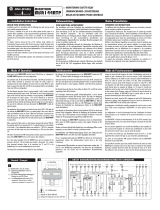
• Um das Verschweißen der Kontakte der eingebauten Re-
lais zu verhindern, ist eine Überstromschutzeinrichtung
mit max. 6 A Kurzschlussschutz (Betriebsklasse gG) in die
Freigabestrompfade einzubinden (siehe Abb. 1, Siche-
rung F2/F3/F4).
5.1 Klemmen-Belegung
Klemme Beschreibung
A1 Spannungsversorgung (+24 V DC)
A2 Spannungsversorgung (0 V DC)
S11 +24 V DC (Steuerspannung)
S33 Versorgung für Rücksetzung
S21 0 V DC (Steuerspannung)
S34 Rücksetzung (fallende Flanke)
S35 Rücksetzung (steigende Flanke)
S12 + Eingangskreis 1 (K1)
S31 + Eingangskreis 2 (K2)
S22 – Eingangskreis 2 (K2)
13–14 Freigabestrompfad 1
23–24 Freigabestrompfad 2
37–38 Rückfallverzögerter Strompfad
5.2 Betriebsarten
Einkanaliger Betrieb
Der Sicherheitssensor wird zwischen S11 und S12 ange-
schlossen. Zwischen S12–S31 und S21–S22 ist jeweils
eine Drahtbrücke anzuschließen.
Zweikanaliger Betrieb mit Querschlusserkennung
Die zwei potenzialfreien Schaltelemente des Sicherheits-
sensors sind zwischen S12–S31 beziehungsweise S21–
S22 anzuschließen. Zwischen S11–S31 ist eine Draht-
brücke anzuschließen.
5.3 Rücksetzung
Manuelle Rücksetzung
Die Rücksetztaste (Schließerkontakt) ist zwischen den Kon-
takten S33 und S34 zu verdrahten. Die Rücksetztaste ist
außerhalb des Gefahrbereichs so zu installieren, dass sie
nicht aus dem Gefahrbereich heraus betätigt werden kann.
Außerdem muss der Benutzer den Gefahrbereich beim
Betätigen vollständig überblicken können.
Automatische Rücksetzung
Zwischen S33–S35 ist eine Drahtbrücke anzuschließen.
5.4 Schützkontrolle
Die Schützkontrolle der eingebundenen Aktoren wird nur
beim Rücksetzen wirksam. Das Verbinden der Öffnerkon-
takte der angesteuerten Schaltglieder in Reihe mit dem
Rücksetzkreis bewirkt eine statische Schützkontrolle.
6 Inbetriebnahme und
regelmäßige Prüfungen
a
Keine Inbetriebnahme ohne Prüfung durch eine
befähigte Person!
Bevor Sie eine durch das Sicherheitsrelais ge-
schützte Anlage erstmals in Betrieb nehmen, muss
die Anlage durch eine befähigte Person überprüft
und dokumentiert freigegeben werden.
> Beachten Sie hierzu die Hinweise in Kapitel 2
„Zur Sicherheit“.
> Beachten Sie die entsprechenden Gesetze und
nationalen Vorschriften.
a
Kontrollieren Sie den Gefahrbereich!
> Stellen Sie vor der Inbetriebnahme sicher, dass
sich niemand im Gefahrbereich aufhält.
> Sichern Sie den Gefahrbereich gegen das
Betreten durch Personen ab.
Regelmäßige Prüfung der Schutzeinrichtungen durch
befähigte Personen
> Prüfen Sie die Anlage entsprechend den national gülti-
gen Vorschriften innerhalb der darin geforderten Fristen.
– Jede Sicherheitsapplikation muss in einem von Ihnen
festgelegten Zeitintervall überprüft werden.
– Die Wirksamkeit der Schutzeinrichtungen muss durch
befugte und beauftragte Personen geprüft werden.
> Wenn Änderungen an der Maschine oder der Schutz-
einrichtung durchgeführt wurden oder das Sicherheits-
relais umgerüstet oder instand gesetzt wurde, dann
müssen Sie die gesamte Sicherheitsapplikation erneut
prüfen.
7 Verhalten im Fehlerfall
a
Kein Betrieb bei unklarem Fehlverhalten!
>
Setzen Sie die Maschine außer Betrieb, wenn Sie
den Fehler nicht eindeutig zuordnen können und
nicht sicher beheben können.
a
Vollständiger Funktionstest nach Fehler-
beseitigung!
> Führen Sie nach der Beseitigung eines Fehlers
einen vollständigen Funktionstest durch.
8 Entsorgung
Entsorgen Sie unbrauchbare Geräte immer gemäß
den jeweils gültigen landesspezifischen Abfall-
beseitigungsvorschriften.
9 Bestelldaten
Artikel
(Ausführung 24 V DC)
Artikelnummer
(Typenschlüssel)
UE45-3S1 (0,15 … 3 s)
mit Schraubklemmen
6024911
(UE45-3S12D33)
UE45-3S1 (0,15 … 3 s)
mit Steckblockklemmen
6024912
(UE45-3S13D33)
UE45-3S1 (1,5 … 30 s)
mit Schraubklemmen
6024913
(UE45-3S12D330)
UE45-3S1 (1,5 … 30 s)
mit Steckblockklemmen
6024914
(UE45-3S13D330)
10 Konformität mit
EU-Richtlinien
UE45-3S1, Safety relays
SICK AG, Erwin-Sick-Straße 1, D-79183 Waldkirch
Sie finden die EU-Konformitätserklärung und die
aktuelle Betriebsanleitung, indem Sie auf
www.sick.com im Suchfeld die Artikelnummer
eingeben (Artikelnummer: siehe Typenschildeintrag im
Feld „Ident. no.“).
Direktlink zur EU-Konformitätserklärung:
www.sick.com/9068882
Der Unterzeichner, der den Hersteller vertritt, erklärt
hiermit, dass das Produkt in Übereinstimmung mit den
Bestimmungen der nachstehenden EU-Richtlinie(n)
(einschließlich aller zutreffenden Änderungen) ist, und
dass die in der EU-Konformitätserklärung
angegebenen Normen und/oder technischen
Spezifikationen zugrunde gelegt sind.
• MACHINERY DIRECTIVE 2006/42/EC
• EMC DIRECTIVE 2014/30/EU
• ROHS DIRECTIVE 2011/65/EU
Waldkirch: 2018-07-10
ppa. Walter Reithofer
Vice President R&D
(GBC Industrial Safety)
authorized for technical
documentation
ppa. Birgit Knobloch
Vice President Operations
(GBC Industrial Safety)
Notified body: No. 0340, DGUV Test, Prüf- und Zerti-
fizierungsstelle Elektrotechnik, Gustav-Heinemann-
Ufer 130, 50968 Köln
EC type-examination: ET 17072

Abb. 2: Beispiel eines einkanaligen Not-Aus mit
manueller Rücksetzung
Abb. 3: Beispiel einer zweikanaligen Schutztür-
absicherung mit Querschluss- und Synchronzeit-
überwachung und manueller Rücksetzung
Abb. 4: Beispiel eines zweikanaligen Not-Aus mit
Querschlussüberwachung, manueller Rücksetzung und
Schützkontrolle
Abb. 5: Beispiel einer zweikanaligen Schutztürabsicherung
mit Querschluss- und Synchronzeitüberwachung, automa-
tischer Rücksetzung und Schützkontrolle
12 Technische Daten
12.1 Datenblatt
Minimal Typisch Maximal
Allgemeine Systemdaten
SIL-Anspruchsgrenze
1)
SILCL3 (EN 62 061)
2)
SILCL2 (EN 62 061)
3)
Hardware-Fehlertoleranz (HFT) 1 (EN 62 061)
Kategorie Kategorie 4 (EN ISO 13 849-1)
2)
Kategorie 3 (EN ISO 13 849-1)
3)
Performance Level
1)
PL e (EN ISO 13 849-1)
2)
PL d (EN ISO 13 849-1)
3)
B
10D
-Wert (Relais) 400 × 10
3
Schaltspiele
4)
PFH
D
(mittlere Wahrscheinlichkeit eines Gefahr bringenden
Ausfalls pro Stunde)
5)
3 × 10
–8 2)
2 × 10
–8 3)
T
M
(Gebrauchsdauer) 20 Jahre (EN ISO 13 849-1)
Stoppkategorie 0/1
3)
(EN 60 204-1)
Versorgungsspannung (A1, A2)
Eingangsspannung (A1, A2), DC 20,4 V 24 V 26,4 V
Leistungsaufnahme 3,1 W
Restwelligkeit bei DC-Betrieb (innerhalb der Grenzen von U
V
) 2,4 V
SS
Steuerspannung S11/S33 und S21
Steuerspannung 22 V DC
Steuerstrom 60 mA
Kurzschlussstrom zwischen S11 und A2 2,2 A
Sicherung PTC-Widerstand
Ansprechzeit bei Querschluss 2 s
Einschaltzeit nach Querschluss 3 s
Galvanische Trennung Nein
Eingangskreise (S12, S31/S22)
Eingangsstrom S12/S31 25 mA 100 mA
Rückfallverzögerungszeit (K1/K2) 25 ms
Rückfallverzögerung K3/K4
(rückfallverzögerter Stromkreis)
Geräte UE45-3S1 1xD3 3 150 ms 3 s
Geräte UE45-3S1 1xD3 30 1,5 s 30 s
Eingangsstrom S33/S34/S35 25 mA 100 mA
Rücksetzzeit
Fallende Flanke (S34) 30 ms
Steigende Flanke (S35) 700 ms
Synchronzeit 500 ms
Betätigungszeit Rücksetztaste (S34) 30 ms
Leitungswiderstand am Eingangskreis 85 Ω
Ausgangsstrompfade (13/14, 23/24, 37/38)
Kontaktwerkstoff und Oberfläche Ag-Legierung, vergoldet
Freigabestrompfade (Schließer) 2
Strompfade (Schließer), zeitverzögert 1
Kontaktart (13/14, 23/24) Zwangsgeführt
Kontaktbelastbarkeit
Schaltspannung AC 10 V 230 V
Schaltspannung DC 10 V 300 V
Schaltstrom 10 mA 6 A
Summenstrom I
sum
12 A
1)
Der tatsächlich erreichte Performance Level hängt von der Applikation ab. Für detaillierte Informationen zur Sicherheits-
auslegung Ihrer Maschine/Anlage setzen Sie sich bitte mit Ihrer zuständigen SICK-Niederlassung in Verbindung.
2)
Gilt für Kontakte 13/14, 23/24.
3)
Gilt für Zeitkontakte 37/38.
4)
Bei maximaler Last.
5)
Bei DC = 99 % und MTTF
D
= 100 a (gemäß EN ISO 13 849-1, Tab. K1 und Formel C.7) und 8760 Schaltspielen/a.
Minimal Typisch Maximal
AC-15 Ue 230 V AC, Ie 4 A (360 Sch/h)
für 13/14 und 23/24
AC-15 Ue 230 V AC, Ie 3 A (360 Sch/h)
für 37/38
Gebrauchskategorie (EN 60 947-5-1)
DC-13 Ue 24 V DC, Ie 4 A (360 Sch/h)
DC-13 Ue 24 V DC, Ie 2 A (3600 Sch/h)
Kontaktabsicherung gG 6 A
Zulässige Schalthäufigkeit 3600/h
Bedingter Kurzschlussstrom 1000 A
Lebensdauer mechanisch 5 x 10
6
Schaltspiele
Betriebsdaten
Berührungsschutz (EN 60 664-1, EN 60 947-1)
Bemessungsstoßspannung U
Imp
4 kV
Überspannungskategorie II
Bemessungsspannnung 300 V AC
Prüfspannung U
eff
50 Hz 2 kV
Schutzart
Gehäuse IP40 (EN 60 529)
Klemmen IP20 (EN 60 529)
Störaussendung EN 55 011
Störfestigkeit EN 60 947-5-1, EN 61 326-3-1
Montage Hutschiene (EN 60 715)
Betriebsumgebungstemperatur –25 °C +55 °C
Lagertemperatur –25 °C +75 °C
Schock 15 g; 11 ms (EN 60 947-5-1)
Schwingen 10–55 Hz; 0,5 mm (EN 60 947-5-1)
Leiterquerschnitte
Eindraht (1×) 0,14 mm² 2,5 mm²
Eindraht (2×, gleicher Querschnitt) 0,14 mm² 0,75 mm²
Feindrahtig mit Aderendhülsen (1×) 0,25 mm² 2,5 mm²
Feindrahtig mit Aderendhülsen (2×, gleicher Querschnitt) 0,2 mm² 0,5 mm²
Zulässiges Anzugsdrehmoment 0,5 Nm 0,6 Nm
Für UL 508- und CSA-Anwendungen
Anschlussquerschnitt
AWG 26-14 (nur 60/75 °C-Kupferlitzen
verwenden)
Anzugsdrehmoment 5–7 lb⋅in
Gewicht 200 g
12.2 Maßbild
Abb. 6: Maßbild UE45-3S1 (mm)
11 Applikationsbeispiele
Abb. 1: Basisbeschaltung UE45-3S1

OPERATING INSTRUCTIONS
UE45-3S1
Safety relay
en
SICK AG • Erwin-Sick-Straße 1
D-79183 Waldkirch • www.sick.com
8009662/10DH/2018-08-02 • REIPA/XX
Printed in Germany (2018-08) • All rights reserved
Subject to change without notice
1 Scope
These operating instructions are only applicable to the
UE45-3S1 safety relays with the following entry on the
type label in the field Operating Instructions: 8009662
You will find the device’s date of manufacture on the
type label in the field Date Code in the format yywwxxxx
(yy = year, ww = calender week, xxxx = serial number).
These operating instructions are original operating
instructions.
2 On safety
This chapter deals with your own safety and the safety
of the equipment operators.
= Please read this chapter carefully before working
with the UE45-3S1 or with the machine protected by
the UE45-3S1.
2.1 Qualified safety personnel
The UE45-3S1 safety relay must only be installed,
commissioned and serviced by qualified safety
personnel.
Qualified safety personnel are defined as persons
who …
• have undergone the appropriate technical training
and
• have been instructed by the responsible machine
operator in the operation of the machine and the
current valid safety guidelines and
• have access to the operating instructions of the
UE45-3S1 safety relay and have read and familia-
rised themselves with them.
2.2 Applications of the device
The UE45-3S1 safety relay can be used:
• in accordance with EN ISO 13 849-1 up to PL e and
category 4
• in accordance with EN 62 061 up to SILCL3
The actual category achieved depends on the external
circuit, the design of the wiring, the selection of the
control switches and their placement on the machine.
The UE45-3S1 safety relay has been evaluated to
UL 508.
The related actuators on the machine or system can be
safely shut down using the safety relay’s output signal
switching contacts.
The UE45-3S1 safety relay is used only for volt-free safety
sensors, e.g.:
• emergency stop pushbuttons (EN ISO 13 850): single-
channel, dual-channel
• safety interlocks (EN 1088): single-channel, dual-
channel
2.3 Correct use
The UE45-3S1 safety relay must be used only as defined in
section 2.2 “Applications of the device”.
It must be used only by qualified safety personnel and only
on the machine where it has been installed and initialised
by qualified safety personnel in accordance with the opera-
ting instructions. If the device is used for any other purposes
or modified in any way — also during mounting and instal-
lation — any warranty claim against SICK AG shall become
void.
2.4 General safety notes and protective
measures
Pay attention to the safety notes and protective
measures!
Please observe the following items in order to en-
sure the correct use of the UE45-3S1 safety relay.
• During the mounting, installation and usage of
the safety relay, observe the standards and
directives applicable in your country.
• The national/international rules and regulations
apply to the installation, commissioning, use and
periodic technical inspection of the safety relay,
in particular:
– Machinery Directive
– Work Equipment Directive
– EMC directive
– the work safety regulations and safety rules
• Manufacturers and operators of the machine on
which a safety relay is used are responsible for
obtaining and observing all applicable safety
regulations and rules.
• The tests must be carried out by qualified safety
personnel or specially qualified and authorised
personnel and must be recorded and documen-
ted to ensure that the tests can be reproduced
and retraced at any time by third parties.
• The operating instructions must be made avail-
able to the operator of the machine where the
UE45-3S1 is used.
• The machine operator is to be instructed in the
use of the device by qualified safety personnel
and must be instructed to read the operating
instructions.
3 Product description
3.1 Structure and operating principle of the
device
The inputs on the UE45-3S1 safety relays are prepared for
the connection of the safety sensors listed in section 2.2
“Applications of the device”. Two separate inputs circuits
control the internal relays. The enable current paths as well
as the delayed reactivation current path are designed as
safe outputs.
3.2 Device functions
Opening of the input circuits results in immediate opening
of two enable current paths and delayed opening of the
third current path. The delay can be continuously adjusted
within the adjustment ranges on the safety relay.
Delayed reactivation current path: This current path opens
with an adjustable delay of 0.15 … 3 s or 1.5 … 30 s in
relation to the two enable current paths.
Manual reset: Closing the input circuits does not result in
immediate closing of the three current paths. This action is
only performed after the actuation of the the reset button.
The reset takes place with the falling or rising edge depen-
ding on the circuit.
Automatic reset: Closing the input circuits results in the
immediate closing of the three current paths. This function
is to be realised with a corresponding circuit.
External device monitoring: The EDM function monitors the
contact elements activated by the enable current paths
(e.g. motor contactors). By wiring the signalling contacts on
the switching elements in series with the reset input, the
enable current paths only close if all switching elements are
open. This control is only effective on reset.
Cross circuit detection: A cross-circuit is detected on the
dual-channel connection of the input circuits, if these are
connected to different polarities.
In order to attain SILCL3/PL e, connect the
external device monitoring!
In order to reach SILCL3/PL e, an external diagno
sis
with DC ≥ 99 % must be applied (i.e. the external
device monitoring must be connected).
Please also read the notes in chapter 11 “Applica-
tion examples”.
3.3 Status indicators
Display Meaning
SUPPLY Ν Green Supply voltage active
K1/K2 Ν Green Relay K1 and K2 active
K3/K4 Ν Green
Delayed reactivation relay K3 and
K4 active
4 Mounting
Mounting only with enclosure rating IP54 or
better!
The safety relay is only allowed to be mounted in the
control cabinet. The control cabinet must at least
comply with enclosure rating IP54.
= Mounting in accordance with EN 50 274.
= The modules are located in a 22.5 mm wide modular
system for 35 mm mounting rails as per EN 60 715.
5 Electrical installation
Switch the entire machine/system off line!
The system can start up unexpectedly while you are
connecting the devices.
• The voltage supply must satisfy the regulations for extra-
low voltages with safe isolation (SELV, PELV) for over-
voltage category III as per EN 60 664 and EN 50 178.
• For installation in environments with overvoltage catego-
ry III, external protection elements must be used. The re-
quired level of protection as per EN 62 305-1 can be
achieved using an external snubber circuit. The protec-
tion elements (SPD – surge protective devices) must
comply with the requirements as per EN 61 643-11.
Note:
The basic insulation of the components connected to the
safety relay must match the highest voltage connected to
the safety relay.
All circuits (and if necessary other EDM) must then also be
designed for the highest voltage level.
• All connections, wiring and cable runs must comply with
the required category as per EN ISO 13 849-1 and the
required SIL claim level as per EN 62 061 (e.g. cables
laid with protection, individually sheathed cable with
screen etc.).
• To protect the contact outputs on the UE45-3S1 and to
increase the service life, the loads connected must be
equipped with, e.g., varistors and RC circuits. Please also
note that the selection of the arc suppression can in-
crease the total response time of the safety function.
• The output signal switching devices and the external
device monitoring (EDM) must be wired in the control
cabinet.
• To prevent the welding of the contacts on the built-in re-
lay, an overcurrent protection device with max. 6 A short-
circuit protection (duty class gG) is to be integrated into
the enable current paths (see Fig. 1, fuse F2/F3/F4).
5.1 Pin assignments
Terminal Description
A1 Voltage supply (+24 V DC)
A2 Voltage supply (0 V DC)
S11 +24 V DC (control voltage)
S33 Supply for reset
S21 0 V DC (control voltage)
S34 Reset (falling edge)
S35 Reset (rising edge)
S12 + Input circuit 1 (K1)
S31 + Input circuit 2 (K2)
S22 – Input circuit 2 (K2)
13–14 Enable current path 1
23–24 Enable current path 2
37–38 Delayed reactivation current path
5.2 Operating modes
Single-channel operation
The safety sensor is connected between S11 and S12. Wire
jumpers are to be connected between S12 and S31 as well
as between S21 and S22.
Dual-channel operation with cross-circuit detection
The two volt-free switching elements on the safety sensor
are to be connected between S12 and S31 as well as
between S21 and S22. A wire jumper is to be connected
between S11 and S31.
5.3 Reset
Manual reset
The reset button (N/O contact) is to be wired to the termi-
nals S33 and S34. The reset button is to be installed out-
side the hazardous area such that it cannot be pressed from
inside the hazardous area. When operating the reset button,
the operator must have full visual command of the hazard-
ous area.
Automatic reset
A wire jumper is to be connected between S33 and S35.
5.4 External device monitoring
The external device monitoring for the actuators integrated
is only effective on reset. The connection of the N/C con-
tacts for the contact elements operated in series with the
reset circuit provides static external device monitoring.
6 Commissioning and regular
tests
Commissioning requires a thorough check by
qualified safety personnel!
Before you operate a system protected by the safety
relay for the first time, make sure that the system is
first checked and released by qualified safety
personnel.
= Please read the notes in chapter 2 “On safety”.
= Observe the relevant laws and national
regulations.
Check the hazardous area!
= Ensure there is nobody in the hazardous area
before commissioning.
= Secure the hazardous area against entry.
Regular inspection of the protective devices by qualified
safety personnel
= Check the system following the inspection intervals
specified in the national rules and regulations.
– Each safety application must be checked at an interval
specified by you.
– The effectiveness of the protective devices must be
checked daily by a specialist or by authorised per-
sonnel.
= If changes have been made to the machine or the pro-
tective device, or the safety relay has been changed or
repaired, you must again thoroughly check the entire
safety application.
7 In the event of faults or errors
Cease operation if the cause of the malfunction
has not been clearly identified!
= Stop the machine if you cannot clearly identify or
allocate the error and if you cannot safely rectify
the malfunction.
Complete function test after rectification of
fault!
= After rectifying a fault, perform a complete
function test.
8 Disposal
Always dispose of serviceableness devices in
compliance with local/national rules and
regulations with respect to waste disposal.
9 Ordering information
Part (24 V DC design) Part number
(type code)
UE45-3S1 (0.15 … 3 s)
with screw type terminals
6024911
(UE45-3S12D33)
UE45-3S1 (0.15 … 3 s)
with removable terminals
6024912
(UE45-3S13D33)
UE45-3S1 (1.5 … 30 s)
with screw type terminals
6024913
(UE45-3S12D330)
UE45-3S1 (1.5 … 30 s)
with removable terminals
6024914
(UE45-3S13D330)
10 Compliance with EU
directives
UE45-3S1, Safety relays
SICK AG, Erwin-Sick-Straße 1, D-79183 Waldkirch
You can call up the EU declaration of conformity and
the current operating instructions by entering the part
number in the search field at www.sick.com (part
number: see the type label entry in the “Ident. no.”
field).
Direct link to EU declaration of conformity:
www.sick.com/9068882
The undersigned, representing the manufacturer, here-
with declares that the product is in conformity with the
provisions of the following EU directive(s) (including all
applicable amendments), and that the standards
and/or technical specifications stated in the EU decla-
ration of conformity have been used as a basis for this.
• MACHINERY DIRECTIVE 2006/42/EC
• EMC DIRECTIVE 2014/30/EU
• ROHS DIRECTIVE 2011/65/EU
Waldkirch: 2018-07-10
ppa. Walter Reithofer
Vice President R&D
(GBC Industrial Safety)
authorized for technical
documentation
ppa. Birgit Knobloch
Vice President Operations
(GBC Industrial Safety)
Notified body: No. 0340, DGUV Test, Prüf- und Zerti-
fizierungsstelle Elektrotechnik, Gustav-Heinemann-
Ufer 130, 50968 Köln
EC type-examination: ET 17072

Fig. 2: Example of single-channel emergency
switching off with manual reset
Fig. 3: Example of dual-channel guard protection with
cross-circuit monitoring and synchronous time
monitoring and manual reset
Fig. 4: Example of dual-channel emergency switching off
with cross-circuit monitoring, manual reset and external
device monitoring
Fig. 5: Example of dual-channel guard protection with
cross-circuit monitoring and synchronous time monitoring,
automatic reset and external device monitoring
12 Technical specifications
12.1 Data sheet
Minimum Typical Maximum
General system data
SIL claim limit
1)
SILCL3 (EN 62 061)
2)
SILCL2 (EN 62 061)
3)
Hardware fault tolerance (HFT) 1 (EN 62 061)
Category Category 4 (EN ISO 13 849-1)
2)
Category 3 (EN ISO 13 849-1)
3)
Performance Level
1)
PL e (EN ISO 13 849-1)
2)
PL d (EN ISO 13 849-1)
3)
B
10D
value (relay) 400 × 10
3
switching operations
4)
PFH
D
(mean probability of a dangerous failure per hour)
5)
3 × 10
–8 2)
2 × 10
–8 3)
T
M
(mission time) 20 years (EN ISO 13 849-1)
Stop category 0/1
3)
(EN 60 204-1)
Supply voltage (A1, A2)
Input voltage (A1, A2), DC 20.4 V 24 V 26.4 V
Power consumption 3.1 W
Residual ripple with DC operation (within the limits of V
S
) 2.4 V
SS
Control voltage S11/S33 and S21
Control voltage 22 V DC
Control current 60 mA
Short-circuit current between S11 and A2 2.2 A
Fuse PTC resistor
Response time in case of cross-circuit 2 s
Switch on time after cross-circuit 3 s
Electrical isolation No
Input circuits (S12, S31/S22)
Input current S12/S31 25 mA 100 mA
Reactivation delay (K1/K2) 25 ms
Reactivation delay K3/K4
(delayed reactivation circuit)
Devices UE45-3S1 1xD3 3 150 ms 3 s
Devices UE45-3S1 1xD3 30 1.5 s 30 s
Input current S33/S34/S35 25 mA 100 mA
Reset time
Falling edge (S34) 30 ms
Rising edge (S35) 700 ms
Synchronous time 500 ms
Reset button operation time (S34) 30 ms
Cable resistance on the input circuit 85 Ω
Output current circuits (13/14, 23/24, 37/38)
Contact material and surface finish Ag alloy, gold-plated
Enable current paths (normally open contact) 2
Current paths (normally open contact), delayed 1
Contact type (13/14, 23/24) Positively guided
Max. contact load
Switching voltage AC 10 V 230 V
Switching voltage DC 10 V 300 V
Switching current 10 mA 6 A
Total current I
sum
12 A
1)
The Performance Level actually attained depends on the application. For detailed information on the safety design of your
machine/system, please contact your local SICK representative.
2)
Valid for contacts 13/14, 23/24.
3)
Applies for time contacts 37/38.
4)
With maximum load.
5)
With DC = 99 % and MTTF
D
= 100 a (according to EN ISO 13 849-1, Tab. K1 and formula C.7) and 8760 switching
operations/a.
Minimum Typical Maximum
AC-15 Ue 230 V AC, Ie 4 A (360 switching
operations/h) for 13/14 and 23/24
AC-15 Ue 230 V AC, Ie 3 A (360 switching
operations/h) for 37/38
Usage category (EN 60 947-5-1)
DC-13 Ue 24 V DC, Ie 4 A (360 switching
operations/h)
DC-13 Ue 24 V DC, Ie 2 A (3600 switching
operations/h)
Contact fuse protection gG 6 A
Permissible switching frequency 3600/h
Rated short circuit current 1000 A
Service life, mechanical 5 x 10
6
switching operations
Operating data
Protection against physical contact (EN 60 664-1, EN 60 947-1)
Rated impulse voltage V
Imp
4 kV
Overvoltage category II
Rated voltage 300 V AC
Test voltage U
rms
50 Hz 2 kV
Enclosure rating
Housing IP40 (EN 60 529)
Terminals IP20 (EN 60 529)
Radiated emissions EN 55 011
Interference resistance EN 60 947-5-1, EN 61 326-3-1
Mounting Mounting rail (EN 60 715)
Ambient operating temperature –25 °C +55 °C
Storage temperature –25 °C +75 °C
Shock 15 g; 11 ms (EN 60 947-5-1)
Vibration 10–55 Hz; 0.5 mm (EN 60 947-5-1)
Wire cross-sections
Single wire (1×) 0.14 mm² 2.5 mm²
Single wire (2×, same cross-section) 0.14 mm² 0.75 mm²
Fine stranded wire with ferrules (1×) 0.25 mm² 2.5 mm²
Fine stranded wire with ferrules (2×, same cross-section) 0.2 mm² 0.5 mm²
Allowed tightening torque 0.5 Nm 0.6 Nm
For UL 508 and CSA applications
Connection cross-section
AWG 26-14
(only use 60/75 °C copper flexible wire)
Tightening torque 5-7 lb⋅in
Weight 200 g
12.2 Dimensional drawing
Fig. 6: Dimensional drawing UE45-3S1 (mm)
11 Application examples
Fig. 1: Basic circuit UE45-3S1

NOTICE D’INSTRUCTIONS
UE45-3S1
Relais de sécurité
fr
SICK AG • Erwin-Sick-Straße 1
D-79183 Waldkirch • www.sick.com
8009662/10DH/2018-08-02 • REIPA/XX
Printed in Germany (2018-08) • Tous droits réservés
Sujet à modification sans préavis
1 Disponibilité des fonctions
Cette notice d’instructions concerne les relais de sécu-
rité UE45-3S1 comportant la mention suivante sur le
champ Operating Instructions de la plaque signalé-
tique : 8009662
La date de fabrication du module est indiquée sur la
plaque signalétique dans le champ Date Code format
aassxxxx (aa = année, ss = n° de semaine, xxxx =
numéro de série).
Cette notice d’instructions est une traduction de la
notice d’instructions d’origine.
2 La sécurité
Ce chapitre est essentiel pour la sécurité tant des
installateurs que des opérateurs de l’installation.
= Lire impérativement ce chapitre avec attention avant
de commencer à mettre en œuvre l’UE45-3S1 ou la
machine protégée par l’UE45-3S1.
2.1 Personnel qualifié
Le relais de sécurité UE45-3S1 ne doit être monté,
installé, mis en service et verifié que par un personnel
qualifié.
Sont qualifiées les personnes qui …
• ont reçu la formation technique appropriée et
• ont été formées par l’exploitant à l’utilisation de
l’équipement et aux directives de sécurité en vigueur
applicables et
• ont accès à la notice d’instructions du relais de
sécurité UE45-3S1 et l’ont lue et assimilée.
2.2 Domaine d’utilisation de l’appareil
Le relais de sécurité UE45-3S1 peut être mis en
œuvre :
• selon EN ISO 13 849-1 jusqu’au niveau de
performance PL e et la catégorie 4
• selon EN 62 061 jusque SILCL3
La catégorie effectivement atteinte dépend du schéma
externe, du câblage, du choix de l’organe de comman-
de et de la façon dont il est raccordé sur place à la
machine.
Le relais de sécurité UE45-3S1 a été testé selon la
norme UL 508.
Via les sorties TOR à contact du relais de sécurité, on
peut produire un arrêt de sécurité des actionneurs
correspondants de la machine ou de l’installation.
Le relais de sécurité UE45-3S1 est exploité exclusivement
avec les capteurs de sécurité à sorties sur contacts secs,
comme :
• interrupteurs d’arrêt d’urgence (EN ISO 13 850) :
monovoie, bivoie
• verrouillages de sécurité (EN 1088) : monovoie, bivoie
2.3 Conformité d’utilisation
Le relais de sécurité UE45-3S1 ne peut être utilisé que
dans les domaines décrits au paragraphe 2.2 « Domaine
d’utilisation de l’appareil ».
Il ne peut en particulier être mis en œuvre que un personnel
qualifié et seulement sur la machine sur laquelle il a été
installé et mis en service initialement par une personne
qualifiée à cet effet selon les prescriptions de cette notice
d’instructions. Pour toute autre utilisation, aussi bien que
pour les modifications – y compris concernant le montage
et l’installation – la responsabilité de la société SICK AG ne
saurait être invoquée.
2.4 Consignes de sécurité et mesures de
protection d’ordre général
Respecter les consignes de sécurité et les
mesures de protection !
Pour garantir la conformité d’utilisation du relais de
sécurité UE45-3S1 il faut observer les points
suivants.
• Il faut s’assurer que le montage, l’installation et
l’utilisation du relais de sécurité sont conformes
aux normes et à la réglementation du pays
d’exploitation.
• Pour le montage et l’exploitation du relais de
sécurité ainsi que pour son mise en service et les
tests réguliers il faut impérativement appliquer
les prescriptions légales nationales et inter-
nationales :
– la directive machine
– la directive d’utilisation des installations
– la directive CEM
– les prescriptions de prévention des accidents
et les règlements de sécurité
• Le fabricant et l’exploitant de la machine à qui
est destiné le relais de sécurité sont responsa-
bles de l’application stricte de toutes les pre-
scriptions et règles de sécurité en vigueur.
• Les tests doivent être exécutés par un personnel
qualifié et/ou des personnes spécialement
autorisées/mandatées ; ils doivent être docu-
mentés et cette documentation doit être dispo-
nible à tout moment.
• La notice d’instructions doit être mise à dispo-
sition de l’opérateur de la machine sur laquelle
l’UE45-3S1 est mis en œuvre.
• L’opérateur de la machine doit être formé par un
personnel qualifié et prendre connaissance de
cette notice d’instructions.
3 Description du produit
3.1 Architecture et mode de fonctionnement
du module
Les entrées des relais de sécurité UE45-3S1 sont conçues
pour le raccordement de capteurs de sécurité tels que
décrits au paragraphe 2.2 « Domaine d’utilisation de
l’appareil ». Deux circuits d’entrées séparés commandent
les relais internes. Les deux contacts de commande et le
circuit temporisé à la retombée constituent des sorties de
sécurité.
3.2 Fonctionnalités
L’ouverture du circuit d’entrée entraîne l’ouverture immédi-
ate de deux contacts de commande et l’ouverture tempo-
risée du troisième circuit. La temporisation est réglable en
continu au niveau du relais de sécurité sur la plage de
réglage.
Circuits temporisés à la retombée : Ce circuit s’ouvre avec
une temporisation réglable de 0,15 à 3 s ou. 1,5 à 30 s par
rapport aux deux contacts de commande.
Réarmement manuel : La fermeture des circuits d’entrée
n’entraîne pas une fermeture immédiate des trois circuits,
celle-ci intervient après que le poussoir de réarmement est
actionné. Selon le câblage, le réarmement se fait sur le
flanc descendant ou bien le flanc montant.
Réarmement automatique : La fermeture du circuit
d’entrée entraîne la fermeture immédiate des trois circuits.
Cette fonction doit être réalisée au moyen du câblage
approprié
Contrôle des contacteurs commandés : Le contrôle des
contacteurs commandés surveille les éléments de commu-
tation commandés par les contacts de commande (par ex.
le contacteur d’un moteur). Le câblage en série des con-
tacts d’état des éléments de commande sur l’entrée de
réarmement n’autorise la fermeture des contacts de
commande que si tous les éléments de contact sont
ouverts. Ce contrôle n’est effectif qu’à partir du
réarmement.
Détection des courts-circuits internes : Avec un câblage
bivoie des circuits d’entrée, un court-circuit interne est
détecté si ces derniers sont de polarités différentes.
Pour atteindre le niveau SILCL3/PL e, raccorder
le contrôle des contacteurs commandés !
Pour atteindre le niveau SILCL3/PL e, il faut utiliser
un diagnostic externe avec DC ≥ 99 % (c.-à-d. que
le contrôle des contacteurs commandés doit être
raccordé).
À cet effet, observer également les instructions du
chapitre 11 « Exemples d’applications ».
3.3 Indicateurs
Indication Interprétation
SUPPLY Ν Vert Tension d’alimentation activée
K1/K2 Ν Vert Relais K1 et K2 activés
K3/K4 Ν Vert
Relais temporisés à la retombée
K3 et K4 activés
4 Montage
Montage uniquement avec indice de protection
IP54 ou plus !
Il est obligatoire de monter le relais de sécurité
dans une armoire électrique. L’armoire électrique
doit satisfaire au moins à l’indice de protection
IP54.
= Montage selon EN 50 274.
= Les modules sont intégrés dans des boîtiers de 22,5 mm
de large pour rail normalisé de 35 mm selon EN 60 715.
5 Installation électrique
Mettre l’installation hors tension !
Pendant le raccordement des appareils, l’instal-
lation pourrait se mettre inopinément en fonction-
nement.
• L’alimentation doit répondre à la réglementation basse
tension avec isolement de protection (TBTS, TBTP) pour la
catégorie III de surtension selon EN 60 664 et
EN 50 178.
• Pour les installations dans un environnement de catégo-
rie III de surtension, il est obligatoire d’utiliser des élé-
ments de protection externe. Les degrés de sécurité obli-
gatoires selon EN 62 305-1 peuvent être atteints au mo-
yen d’un circuit de protection externe. Les éléments de
protection (SPD - surge protective devices) utilisés doi-
vent répondre aux exigences de la norme EN 61 643-11.
Remarque :
Les composants raccordés au module de relayage de
sécurité doivent avoir une isolation de base correspondant
à la tension la plus élevée connectée au module de
relayage de sécurité.
Tous les circuits (et le cas échéant des EDM additionnels)
doivent également être conçus pour cette tension la plus
élevée.
• Tous les raccordements ainsi que le câblage et les
chemins de câble doivent être conformes à la catégorie
selon EN ISO 13 849-1 et selon EN 62 061 (par ex.
chemins de câble protégés, conducteurs en gaine
individuelle avec blindage, etc.).
• Afin de protéger les contacts de sortie de l’UE45-3S1 et
d’augmenter leur durée de vie, les charges externes
raccordées doivent être antiparasitées par ex. par des
varistors et des cellules RC. Observer que ces
équipements selon leur nature augmentent plus ou
moins le temps de réponse.
• Les sorties de sécurité et le contrôle des contacteurs
commandés (EDM) doivent être câblés à l’intérieur
même de l’armoire.
• Pour empêcher que les contacts des relais intégrés ne se
soudent, il faut installer dans le contact de commande
une protection contre les surintensités protégeant des
courts-circuits de 6A max. (classe de service gG) (cf.
Fig. 1, sécurité des contacts de commande F2/F3/F4).
5.1 Affectation des bornes
Borne Description
A1 Alimentation (+24 V CC)
A2 Alimentation (0 V CC)
S11 +24 V CC (Tension de commande)
S33 Alimentation pour le réarmement
S21 0 V CC (Tension de commande)
S34 Réarmement (flanc descendant)
S35 Réarmement (flanc montant)
S12 + Circuit d’entrée 1 (K1)
S31 + Circuit d’entrée 2 (K2)
S22 – Circuit d’entrée 2 (K2)
13–14 Contact de commande 1
23–24 Contact de commande 2
37–38 Circuits temporisés à la retombée
5.2 Modes de fonctionnement
Service monovoie
Le capteur de sécurité se connecte entre S11 et S12. Il faut
câbler un cavalier entre S12 et S31 et entre S21 et S22.
Service bivoie avec détection des courts-circuits
internes
Selon le cas, connecter les deux éléments de commutation
à contact sec du capteur de sécurité entre S12 et S31 ou
S21 et S22. Il faut câbler un cavalier entre S11 et S31.
5.3 Réarmement
Réarmement manuel
Le poussoir de réarmement (contact NO) se raccorde sur les
bornes S33 et S34. Le poussoir de réarmement doit être
installé à l’extérieur de la zone dangereuse de manière qu’il
soit impossible de l’actionner depuis la zone dangereuse.
En outre, la zone dangereuse doit être entièrement visible
par l’opérateur qui actionne le dispositif de commande
manuel.
Réarmement automatique
Il faut câbler un cavalier entre S33 et S35.
5.4 Contrôle des contacteurs commandés
Le contrôle des contacteurs commandés des acteurs
connectés n’est effectif qu’à partir du réarmement. Le
câblage des contacts NF des éléments de commutation
commandés en série dans le circuit de réarmement réalise
le contrôle statique des contacteurs commandés.
6 Mise en service et contrôles
périodiques
Un personnel qualifié doit effectuer des tests de
validation pour que la mise en service soit
effective !
Un personnel qualifié doit tester et valider dans un
rapport l’installation protégée par un relais de
sécurité, avant sa première mise en service.
= Dans ce but, observer les conseils prodigués
chapitre 2 « La sécurité ».
= Il faut respecter la législation correspondante et
les prescriptions nationales.
Contrôler la zone dangereuse !
= Avant la mise en service, il faut s’assurer que
personne ne se trouve dans la zone dangereuse.
= Faire en sorte que personne ne puisse pénétrer
dans la zone dangereuse.
Un personnel qualifié doit effectuer un test régulier des
équipements de protection
= Il faut effectuer des tests en temps voulu en conformité
avec les prescriptions nationales en vigueur.
– Chaque application de sécurité doit être contrôlée à
intervalle régulier fixé par l’exploitant.
– L’efficacité de l’équipement de protection doit être
vérifiée chaque jour par un personnel autorisé et dont
c’est la mission.
= Lorsque des modifications sont effectuées sur la machi-
ne ou sur l’équipement de protection, ou encore en cas
de modification ou de réparation du relais de sécurité, il
est nécessaire de contrôler de nouveau l’ensemble de
l’application de sécurité.
7 Comportement en cas de
défaillance
Ne jamais travailler avec un système dont la
sécurité pourrait être mise en doute !
= Mettre la machine hors service si la défaillance
ne peut pas être identifiée ni éliminée avec
certitude.
Effectuer un test complet après l’élimination
d’un défaut !
= Après élimination d’un défaut de la barrière, il
faut effectuer un test fonctionnel complet.
8 Mise au rebut
Les appareils inutilisables doivent être mis a
u rebut
dans le respect de la législation sur l’élimination
des déchets en vigueur dans le pays d’installation.
9 Références
Article (version 24 V CC) Référence
(désignation)
UE45-3S1 (0,15 … 3 s)
à borniers à vis
6024911
(UE45-3S12D33)
UE45-3S1 (0,15 … 3 s)
à borniers enfichables
6024912
(UE45-3S13D33)
UE45-3S1 (1,5 … 30 s)
à borniers à vis
6024913
(UE45-3S12D330)
UE45-3S1 (1,5 … 30 s)
à borniers enfichables
6024914
(UE45-3S13D330)
10 Conformité aux directives UE
UE45-3S1, Safety relays
SICK AG, Erwin-Sick-Straße 1, D-79183 Waldkirch
Pour trouver la déclaration de conformité UE et la
notice d’instruction actuelle, taper le numéro d’article
dans le champ de recherche de notre site internet
www.sick.com (numéro d’article : voir numéro de
plaque signalétique dans le champ « Ident. no. »).
Lien direct vers la déclaration de conformité UE :
www.sick.com/9068882
Le soussigné, représentant le constructeur, déclare par
la présente que le produit est conforme aux exigences
de la (des) directive(s) de l’UE suivantes (y compris
tous les amendements applicables) et que les normes
et/ou spécifications techniques dans la déclaration de
conformité UE ont servi de base.
• MACHINERY DIRECTIVE 2006/42/EC
• EMC DIRECTIVE 2014/30/EU
• ROHS DIRECTIVE 2011/65/EU
Waldkirch: 2018-07-10
ppa. Walter Reithofer
Vice President R&D
(GBC Industrial Safety)
authorized for technical
documentation
ppa. Birgit Knobloch
Vice President Operations
(GBC Industrial Safety)
Notified body: No. 0340, DGUV Test, Prüf- und Zerti-
fizierungsstelle Elektrotechnik, Gustav-Heinemann-
Ufer 130, 50968 Köln
EC type-examination: ET 17072

Fig. 2 : Exemple d’un arrêt d’urgence monovoie avec
réarmement manuel
Fig. 3 : Exemple d’une protection de porte bivoie avec
surveillance des courts-circuits interne, contrôle de
synchronisation et réarmement manuel
Fig. 4 : Exemple d’un arrêt d’urgence bivoie avec
surveillance des courts-circuits interne, réarmement
manuel et contrôle des contacteurs commandés
Fig. 5 : Exemple d’une protection de porte bivoie avec
surveillance des courts-circuits interne, contrôle de
synchronisation, réarmement automatique et contrôle des
contacteurs commandés
12 Caractéristiques techniques
12.1 Fiche de spécifications
Minimum Typique Maximum
Caractéristiques générales
Limite d’exigence SIL
1)
SILCL3 (EN 62 061)
2)
SILCL2 (EN 62 061)
3)
Tolérance de défaillances du matériel (HFT) 1 (EN 62 061)
Catégorie Catégorie 4 (EN ISO 13 849-1)
2)
Catégorie 3 (EN ISO 13 849-1)
3)
Performance Level
1)
PL e (EN ISO 13 849-1)
2)
PL d (EN ISO 13 849-1)
3)
Valeur B
10D
(relais) 400 × 10
3
manœuvres
4)
PFH
D
(probabilité de défaillance dangereuse par heure)
5)
3 × 10
–8 2)
2 × 10
–8 3)
T
M
(durée d’utilisation) 20 ans (EN ISO 13 849-1)
Catégorie d’arrêt 0/1
3)
(EN 60 204-1)
Tension d’alimentation (A1, A2)
Tension d’entrée (A1, A2), CC 20,4 V 24 V 26,4 V
Puissance consommée 3,1 W
Ondulation résiduelle en fonctionnement en CC
(dans les limites de U
V
)
2,4 V
SS
Tension de commande S11/S33 et S21
Tension de commande 22 V CC
Courant de commande 60 mA
Courant de court-circuit entre S11 et A2 2,2 A
Protection Résistance CTP
Temps de réponse au court-circuit interne 2 s
Retard à la mise sous tension après court-circuit interne 3 s
Séparation galvanique Non
Circuits d’entrée (S12, S31/S22)
Courant d’entrée S12/S31 25 mA 100 mA
Délai de retombée des relais (K1/K2) 25 ms
Délai de retombée des contacts K3/K4
(circuit temporisé à la retombée)
Modules UE45-3S1 1xD3 3 150 ms 3 s
Modules UE45-3S1 1xD3 30 1,5 s 30 s
Courant d’entrée S33/S34/S35 25 mA 100 mA
Temps de réarmement
Flanc descendant (S34) 30 ms
Flanc montant (S35) 700 ms
Temps de synchronisation 500 ms
Durée de manœuvre du poussoir de réarmement (S34) 30 ms
Résistance du circuit d’entrée 85 Ω
Circuits de sortie (13/14, 23/24, 37/38)
Matériau de contact et état de surface Alliage Ag, doré
Contacts de commande (contact NO) 2
Circuits (contact NO), temporisés 1
Type de contact (13/14, 23/24) Guidé
Charge admissible par les contacts
Tension de commutation CA 10 V 230 V
Tension de commutation CC 10 V 300 V
Courant de commutation 10 mA 6 A
Courant total I
sum
12 A
1)
Le niveau Performance Level effectivement atteint dépend de l’application. Pour obtenir des informations détaillées sur la
conception de sécurité de la machine/installation, prendre contact avec l’agence SICK la plus proche.
2)
Valable pour les contacts 13/14, 23/24.
3)
Valable pour les contacts de temps 37/38.
4)
À la charge maximale.
5)
Avec CC = 99 % et MTTF
D
= 100 a (selon EN ISO 13 849, tab. K1 et formule C.7) et 8760 manœuvres/a.
Minimum Typique Maximum
CA-15 Ue 230 V CA, Ie 4 A (360 cmmt/h)
pour 13/14 et 23/24
CA-15 Ue 230 V CA, Ie 3 A (360 cmmt/h)
pour 37/38
Catégorie d’utilisation (EN 60 947-5-1)
CC-13 Ue 24 V CC, Ie 4 A (360 cmmt/h)
CC-13 Ue 24 V CC, Ie 2 A (3600 cmmt/h)
Protection des contacts gG 6 A
Fréquence de commutation admissible 3600/h
Courant de court-circuit assigné 1000 A
Durée de vie mécanique 5 x 10
6
manœuvres
Données opérationnelles
Protection contre le contact (EN 60 664-1, EN 60 947-1)
Tension impulsionnelle de mesure U
Imp
4 kV
Catégorie de surtension II
Tension de mesure 300 V CA
Tension d’essai U
eff
50 Hz 2 kV
Indice de protection
Boîtier IP40 (EN 60 529)
Bornes IP20 (EN 60 529)
Émissions parasites EN 55 011
Immunité aux perturbations EN 60 947-5-1, EN 61 326-3-1
Montage Rail de montage (EN 60 715)
Température ambiante de fonctionnement –25 °C +55 °C
Température de stockage –25 °C +75 °C
Choc 15 g ; 11 ms (EN 60 947-5-1)
Vibrations 10–55 Hz ; 0,5 mm (EN 60 947-5-1)
Sections du conducteur
Un conducteur (1×) 0,14 mm² 2,5 mm²
Un conducteur (2×, section identique) 0,14 mm² 0,75 mm²
Conducteurs toronnés avec manchons (1×) 0,25 mm² 2,5 mm²
Conducteurs toronnés avec manchons (2×, section identique) 0,2 mm² 0,5 mm²
Couple de serrage admissible 0,5 Nm 0,6 Nm
Pour les applications UL 508 et CSA
Section des fils de raccordement
AWG 26-14 (utiliser uniquement des
conducteurs multibrins résistants à 60/75 °C)
Couple de serrage 5–7 lb⋅in
Poids 200 g
12.2 Schéma coté
Fig. 6 : Schéma coté UE45-3S1 (mm)
11 Exemples d’applications
Fig. 1 : Schéma de base du module UE45-3S1
1/6