
Operating Instructions
Betriebsanleitung
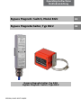
Bypass Magnetic Switch, Model BGU
EN
Bypass Magnetschalter, Typ BGU
DE
Bypass-Magnetschalter, Typ BGU
Bypass Magnetic Switch, Type BGU
123916/ 09.02.2017 EN/DE

2 KSR KUEBLER Operating instructions Bypass magnetic switch - BGU
EN
Operating Instructions, Model BGU
DE
Betriebsanleitung, Typ BGU
© 2016 WIKA Alexander Wiegand SE & Co. KG
All rights reserved. / Alle Rechte vorbehalten.
WIKA® and KSR® are registered trademarks in various countries.
WIKA® and KSR® sind geschützte Marken in verschiedenen Ländern.
Prior to starting any work, read the operating instructions!
Keep for later use!
Vor Beginn aller Arbeiten Betriebsanleitung lesen!
Zum späteren Gebrauch aufbewahren!
Manufacturer contact
hergestellt von
Sales contact
Vertrieb durch
KSR Kuebler Niveau-Messtechnik AG
Heinrich-Kuebler-Platz 1
69439 Zwingenberg am Neckar • Germany
Tel. +49 6263/87-0
Fax +49 6263/87-99
info@ksr-kuebler.com
www.ksr-kuebler.com
WIKA Alexander Wiegand SE & Co. KG
Alexander-Wiegand-Straße 30
63911 Klingenberg • Germany
Tel. +49 9372 132-0
Fax +49 9372 132-406
www.wika.de

KSR KUEBLER Operating instructions Bypass magnetic switch– BGU 3
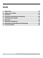
Contents
1. General information 4
2. Design and function 5
3. Safety 6
4. Transport, packaging and storage 11
5. Commissioning, operation 12
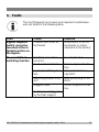
6. Faults 21
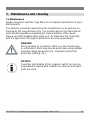
7. Maintenance and cleaning 23
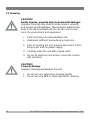
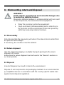
8. Dismounting, return and disposal 25
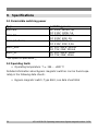
9. Specifications 26

4 KSR KUEBLER Operating instructions Bypass magnetic switch - BGU
1. General information
The magnetic switches described in the operating instructions are de-
signed and manufactured in accordance with the current state-of-the-
art. During production, all components are subject to strict quality and
environmental criteria. Our management systems are certified in ac-
cordance with ISO 9001.
These operating instructions provide information on how to use the unit.
Compliance with all specified safety instructions and work instructions
are a prerequisite for working safely.
Compliance with the local applicable accident prevention regulations
and general safety regulations for the area of use of the unit is required.
The operating instructions are a component of the product and must be
kept in the immediate vicinity of the unit where they are accessible to
the technicians at all times. Pass on the operating instructions to sub-
sequent users or owners of the unit.
The technicians must read and understand the operating instructions
prior to starting any work.
The general terms and conditions from the sales documents apply.
Technical changes reserved.
Additional information:
- Internet address: www.ksr-kuebler.com or www.wika.com

KSR KUEBLER Operating instructions Bypass magnetic switch– BGU 5
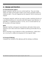
2. Design and function
2.1 Functional description
Bypass magnetic switches are non-contact switches. They are mainly
made of a switch housing with a built-in reed contact, proximity switch or
rotational switch. They are triggered by the magnetic field of a permanent
magnet.
The Bypass magnetic switches are used to provide a switching function at
a pre-determined level in connection with KSR bypass level indicators of
type BNA or comparable products. For this, one or several switches can
be mounted on the level indicator
Note:
Magnetic Switches and bypass level indicators with built-in float are de-
signed for each other and ensure reliable functioning and trouble-free op-
eration.
When mounting on level indicators of other manufacturers, malfunctions
can occur due to a different arrangement of the magnetic fields.
2.2 Scope of delivery
Compare the contents of the delivery with the delivery certificate.

6 KSR KUEBLER Operating instructions Bypass magnetic switch - BGU
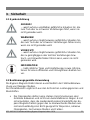
3. Safety
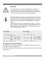
3.1 Symbols
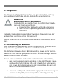
DANGER!
... indicates an immediately hazardous situation which
might result in death or severe injuries if it is not avoided.
WARNING!
... indicates an potentially hazardous situation which might
result in death or severe injuries if it is not avoided.
CAUTION!
... indicates an potentially hazardous situation which might
result in light or minor injuries or property or environmental
damages if it is not avoided.
INFORMATION
... highlights useful tips and recommendations and infor-
mation for efficient and fault-free operation.
3.2 Proper intended use
The Bypass magnetic switches are solely intended for monitoring the liquid
level of fluids. The area of use is based on the technical performance limits
and materials.
The fluids must not be contaminated nor contain coarse particles
nor tend to crystallize. It must be ensured that the magnetic switch
materials that come into contact with the media are sufficiently re-
sistant to the monitored medium. Not suitable for dispersion, abra-
sive fluids, highly viscous media and paints.
Compliance with the usage conditions specified in the operating in-
structions is required.
Do not operate the unit in direct proximity of ferro-magnetic envi-
ronments (distance min. 50mm).

KSR KUEBLER Operating instructions Bypass magnetic switch– BGU 7
Do not operate the unit in direct proximity of strong electromagnetic
fields or in direct proximity of facilities that can be impacted by
magnetic fields (distance min. 1m).
The magnetic switches may not be subjected to strong mechanical
stresses (impact, bending, vibrations). The unit is exclusively de-
signed and constructed for the intended use described here and
may only be used accordingly.
The switching points of the magnetic switch cannot be adjusted.
These instructions are intended for technicians who execute the in-
stallation and calibration.
Compliance with the relevant safety regulations for the use is re-
quired.
Compliance with the technical specifications in these operating in-
structions is required. Improper use or operation of the unit outside
the technical specifications requires immediate shut-down and in-
spection by an authorized WIKA service technician.
Claims of any kind due to improper use are excluded.
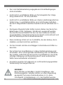
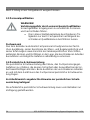
DANGER!
When working on containers, there is a riSK of poisoning
or suffocation. Work may only be performed using suitable
personal safety equipment (e.g. respiratory protection,
protective clothing, etc.).
3.3 Improper use
Any use that exceeds the technical performance thresholds or that is in-
compatible with the materials is considered improper use.
WARNING!
Injury due to improper use
Improper use of the unit can result in hazardous situations
and injuries.
Do not modify the unit without authorization
Do not use the unit in potentially explosive areas.

8 KSR KUEBLER Operating instructions Bypass magnetic switch - BGU
Any use beyond the proper intended use or any other use is considered
improper use.
Do not use this unit in safety or emergency off equipment.
3.4 Responsibility of the operator
The unit is used in the industrial sector. The operator is therefore subject
to statutory obligations with respect to occupational safety.
Compliance with the safety instructions in these operating instructions and
the applicable safety, accident prevention and environmental protection
regulations for the area of use of the unit is required.
In order to safely work on the unit, the operator must ensure
the operating personnel is regularly trained in all matters pertaining
to occupational safety, first aid and environmental conservation and
is familiar with the operating instructions and, in particular, the safe-
ty instructions contained therein
the unit is suitable for the application in accordance with the proper
intended use (check for improper use).
After check, improper use is excluded.
3.5 Personnel qualification
WARNING!
Risk of injury due to insufficient qualifications
Improper use can result in significant personal injury and
property damages.
The activities described in these operating instruc-
tions may only be performed by specialist techni-
cians with the following qualifications.
Specialist personnel
The specialist personnel authorized by the operator is capable of execut-
ing the described work and autonomously detect potential hazards due
their technical training, knowledge of measuring and control technology

KSR KUEBLER Operating instructions Bypass magnetic switch– BGU 9
and their experience and knowledge of country-specific regulations, appli-
cable standards and guidelines.
3.6 Personal safety equipment
The personal safety equipment serves to protect the technicians against
hazards that might impact the safety or health while working. When exe-
cuting the various tasks on and with the unit, the technicians must wear
personal safety equipment.
Comply with warning signs posted in the work area regarding per-
sonal safety equipment!
The required personal safety equipment must be provided by the operator.

10 KSR KUEBLER Operating instructions Bypass magnetic switch - BGU
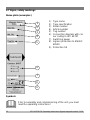
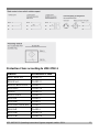
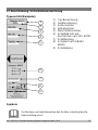
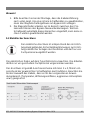
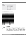
3.7 Signs, safety markings
Name plate (examples)
1) Type name
2) Type specification
3) Serial number
4) Article number
5) Tag number
6) Connection diagram with col-
our coding to IEC 60757
7) Switching power
8) Ingress protection to EN/IEC
60529
9) Protection SK
Symbols
Prior to assembly and commissioning of the unit, you must
read the operating instructions!
2
3
4
5
8
9
6
1
7

KSR KUEBLER Operating instructions Bypass magnetic switch– BGU 11
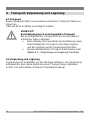
4. Transport, packaging and storage
4.1 Transport
Check the magnetic switch for potential transport damage.
Immediately report obvious damage.
CAUTION!
Damage due to improper transport
Improper transport can result in significant property dam-
ages.
When unloading packages upon delivery and for in-
ternal facility transport, proceed carefully and comply
with the symbols on the packaging.
For internal facility transport, follow the instructions
in Chapter 4.2 “Packaging and storage”
4.2 Transport and storage
Remove packaging immediately prior to assembly. Keep the packaging as
it provides optimum protection during transport (e.g. changing installation
location, repair shipment).

12 KSR KUEBLER Operating instructions Bypass magnetic switch - BGU
5. Commissioning, operation
Comply with all of the instructions on the packaging pertaining to removing
the transport locks.
Remove the magnetic switch from the packaging carefully!
When unpacking, check all parts for external damage.
Functional test before assembly:
The functional test is carried out to determine the proper
functioning of the switching contacts. You should discon-
nect the power connection between the control and the
switch before the test. You can determine the switching
condition e.g. with a continuity tester. You can carry out
the functional test by actuating the contact with a perma-
nent magnet with a radial magnetic field in the switching
area. For this, you should move the magnet alongside the
Magnetic Switch from the bottom towards the top. When
doing so, the contact should switch over. Afterwards, you
should move the magnet again from the top towards the
bottom. The contact is falling back into its initial position.
Instead of the magnet, you can also use the built-in float of
the bypass level indicator
During the functional test, unintentional processes can be
triggered off in the downstream control. Risk of physical
injuries and property damage. Competent technical staff
only should connect and disconnect power lines. Do not
operate Magnetic Switches in the immediate proximity of
powerful electromagnetic fields (distance should be at
least 1m).
Do not expose Magnetic Switches to strong mechanical
loads.

KSR KUEBLER Operating instructions Bypass magnetic switch– BGU 13
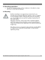
5.1 Mounting preparations
Ensure the sealing surface of the container or the BGU is clean
and has no mechanical damage.
5.2 Mounting
Before mounting in an aggressive environment, you
should ensure that the Magnetic Switch's case is resistant
to it accordingly. When choosing the place for mounting,
you should take into account the system of protection of
the used switch.
Magnetic Switches, which have been supplied together
with KSR bypass level indicators, are pre-assembled al-
ready and should just be adjusted to the desired switching
height only.
Mounting occurs on magnetic roller indicator (model BMD)
on bypass level indicator (model BNA) or directly with
tightening straps.

14 KSR KUEBLER Operating instructions Bypass magnetic switch - BGU
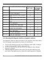
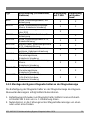
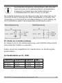
Type
Description (Switch, housing)
Attachment
with T-slot
Attachment
with tighten-
ing straps
BGU
Reed, aluminium case, cable out-
let
X
X
BGU-A
Reed, aluminium connection
housing, cable gland
X
X
BGU-M12
Reed, aluminium case, connector
M12
X
BGU-V
Reed, stainless steel case, cable
outlet
X
BGU-AD
Reed, aluminium case ATX, cable
entry
X
X
BGU-AM
Micro switch, aluminium case
ATX, cable entry
X
X
BGU-AIH
Proximity switch, high alarm,
aluminium case, cable gland
X
X
BGU-AIL
Proximity switch, low alarm, alu-
minium case, cable gland
X
X
BGU-AR
Rotational switch, aluminium
case, cable gland
X
X
BGU-AHT
Reed, high temperature, alumini-
um case, cable gland
X
X
BGU-VHT
Reed, high temperature, stainless
steel case, cable gland
X
X
5.2.1 Mounting the Magnetic Switch on magnetic indicator
The Magnetic Switches will be mounted on the magnetic roller level indica-
tor of the bypass level indicator by means of t-slot stones.
1. Unscrew the fastening screws at the Magnetic Switch with a hexagon
socket screw key WAF 3mm by about one turn.
2. Insert the t-slot block(s) into the slot of the magnetic roller indicator
from top or bottom.
3. Shift the Magnetic Switch to the level of the desired switching point
and fasten it by tightening the screws (the switching point is marked).

KSR KUEBLER Operating instructions Bypass magnetic switch– BGU 15
The Magnetic Switches can be mounted on both sides of the magnetic
roller level indicators optionally. For this, you should mount the t-slot block
on the switch's opposite side. The assembly at works is done on the by-
pass level indicator's right side.
When mounting several Magnetic Switches on the bypass level indicator,
we recommend mounting them on both sides of the magnetic roller indica-
tor alternately. Thus, it is ensured that any desired switching height can be
adjusted.
Attention!
The Magnetic Switch BGU-A is designed to be mounted
on the right side of the magnetic roller indicator. When
mounted on the left side, the switching function is re-
versed. The switch should be mounted upside down (the
name plate is turned upside down).
5.2.2 Mounting of Magnetic Switch with tightening straps
1. Open the fixing band by loosening the adjustment screw.
2. Slide the fixing band through the opening on the magnetic switch
3. Attach the fixing band to the bypass chamber and tighten via adjust-
ment screw, so that the magnetic switch can still be moved.
4. Slide the magnetic switch to the desired switching height and fix into
position by tightening the screw. (The switch point is marked).

16 KSR KUEBLER Operating instructions Bypass magnetic switch - BGU
Attention!
Magnetic switches BGU-AD and BGU-AM are mounted
with 2 tightening straps.
Note!
1. When mounting, please pay attention to that the cable entry faces
downwards. In order to ensure a safe switching function, the Mag-
netic Switch's case should sit close to the bypass pipe.
2. The Magnetic Switches do only work in the area between the by-
pass level indicator's process connections. We cannot guarantee a
safe functioning if a switching point is set outside that area.
5.3 Electrical connection
The electrical connection must be established in
accordance with the application construction regulations in
the country of installation and may only be performed by
specialist personnel.
The connection should be carried out pursuant to the connection diagram
with at least 3 x 0,75mm² according to the desired switching function.
When selecting the cable, please pay attention to that it is suitable for the
planned area of application (temperature, weather influences, aggressive
atmosphere etc.).

KSR KUEBLER Operating instructions Bypass magnetic switch– BGU 17
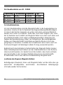
Protection Class according to VDE 0702-1
Switch
Protection Class
BGU, BGU-GL
CLASS II
BGU-Ex d
CLASS II
BGU-A; BGU-A-GL
CLASS I
BGU-M12
CLASS III
BGU-V
CLASS II
BGU-V-Ex d
CLASS II
BGU-AD
CLASS I
BGU-AM
CLASS I
BGU-AIH / BGU-AIL
CLASS I
BGU-AR
CLASS I
BGU-AHT
CLASS III
BGU-VHT
CLASS III

18 KSR KUEBLER Operating instructions Bypass magnetic switch - BGU
Warnung!
The operation of the Magnetic Switches at inductive or
capacitive load can result in the destruction of the reed
contact. This can lead to a malfunction of the downstream
control and to physical injury or property damage.
With inductive load, please protect the Magnetic Switches
by wiring with a RC module (see appendix) or with a shunt
diode. The use of varistors protective wiring is not permit-
ted for the reed contact can be destroyed by occurring
peaks.
With capacitive load, line lengths above 50m, or connec-
tion to process control systems with capacitive input a pro-
tective resistor of 22 Ω should be connected in series to
the to limit the peak current.
RC modules for switch protection
Depending on the operating voltage, RC modules should only be used in
accordance with the table below.
Other RC modules that those listed here will result in the destruction of the
Reed switch.

KSR KUEBLER Operating instructions Bypass magnetic switch– BGU 19
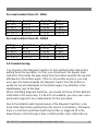
For reed contacts from 10 - 40VA
Voltage
Resistance
Capacity
Type
AC 24 V
100 Ω
0,33 µF
A 3/24
AC 48 V
220 Ω
0,33 µF
A 3/48
AC 115 V
470 Ω
0,33 µF
A 3/115
AC 230 V
1500 Ω
0,33 µF
A 3/230
For reed contacts from 40 - 100VA
Voltage
Resistance
Capacity
Type
AC 24 V
47 Ω
0,33 µF
B 3/24
AC 48 V
100 Ω
0,33 µF
B 3/48
AC 115 V
470 Ω
0,33 µF
B 3/115
AC 230 V
1000 Ω
0,33 µF
B 3/230
5.4 Commissioning
You should set the Magnetic Switches to their defined initial state before
putting them into operation. For this, you should push the bypass level
indicator's float inside the pipe slowly from the bottom towards the top and
afterwards to the bottom again. If this is not possible anymore, you may
even pass the float alongside the Magnetic Switch from the bottom to-
wards the top and afterwards to the bottom again. Pay attention to the
identification „top“ at the float.
When retrofitting Magnetic Switches, you should set these to their defined
initial state in the same way. If a float is not available, you may even use a
permanent magnet of any radial polarity for this procedure.
Due to the bistable switching behaviour of the Magnetic Switches, a de-
fined initial state before putting them into service is mandatory. Otherwise,
there is a risk that a defective switching function is triggered off in the
downstream control through a false contact position upon initial start-up.

20 KSR KUEBLER Operating instructions Bypass magnetic switch - BGU
Adjustment of the Magnetic Switch
Unscrew the fastening screw(s) and shift the Magnetic Switch to the level
of the desired switching point.
Tighten the fastening screw again afterwards.
Seite wird geladen ...
Seite wird geladen ...
Seite wird geladen ...
Seite wird geladen ...
Seite wird geladen ...
Seite wird geladen ...
Seite wird geladen ...
Seite wird geladen ...
Seite wird geladen ...
Seite wird geladen ...
Seite wird geladen ...
Seite wird geladen ...
Seite wird geladen ...
Seite wird geladen ...
Seite wird geladen ...
Seite wird geladen ...
Seite wird geladen ...
Seite wird geladen ...
Seite wird geladen ...
Seite wird geladen ...
Seite wird geladen ...
Seite wird geladen ...
Seite wird geladen ...
Seite wird geladen ...
Seite wird geladen ...
Seite wird geladen ...
Seite wird geladen ...
Seite wird geladen ...
Seite wird geladen ...
Seite wird geladen ...
Seite wird geladen ...
Seite wird geladen ...
-
 1
1
-
 2
2
-
 3
3
-
 4
4
-
 5
5
-
 6
6
-
 7
7
-
 8
8
-
 9
9
-
 10
10
-
 11
11
-
 12
12
-
 13
13
-
 14
14
-
 15
15
-
 16
16
-
 17
17
-
 18
18
-
 19
19
-
 20
20
-
 21
21
-
 22
22
-
 23
23
-
 24
24
-
 25
25
-
 26
26
-
 27
27
-
 28
28
-
 29
29
-
 30
30
-
 31
31
-
 32
32
-
 33
33
-
 34
34
-
 35
35
-
 36
36
-
 37
37
-
 38
38
-
 39
39
-
 40
40
-
 41
41
-
 42
42
-
 43
43
-
 44
44
-
 45
45
-
 46
46
-
 47
47
-
 48
48
-
 49
49
-
 50
50
-
 51
51
-
 52
52


in anderen Sprachen
- English: WIKA BGU Operating instructions
Verwandte Artikel
-
WIKA BGU Bedienungsanleitung
-
-
-
-
-
WIKA OLS-H tag:model:OLS-S Bedienungsanleitung
-
-
-
-