DURKOPP ADLER 176 Benutzerhandbuch

Typ
Benutzerhandbuch
1. Verwendung des Teilesatzes
Der Teilesatz “Bandzuführung” ist für Kettenstichmaschinen der
Klasse 176 vorgesehen.
2. Komponenten des Teilesatzes
Der Teilesatz besteht aus folgenden Bauteilen:
1 x Armdeckel
1 x Befestigungswinkel kpl. bestehend aus:
1 x Befestigungswinkel (0176 340080)
1 x Block (0176 340060)
2 x Sechskantschraube M6 x 16 (9201 113297)
1 x Scheibe B 6,4 (9330 900117)
1 x Gewindestift M6 x 8H (9205 102477)
1 x Achse (0794 006813)
1 x Stellring mit Bremskone (N900 001351)
1 x Stellring (N900 001361)
1 x Lisierbandführung (0176 340070)
2 x Linsenschraube M4 x 12 H (9204 201677)
1 x Linsenschraube M4 x 6 H (9204 201647)
4 x Linsenschraube M4 x 16 H (9204 201697)
Anbauanleitung Bandzuführung
für Teilesatz 0176 590034
Fitting Instructions Tape Feeder
Kit 0176 590034
Teile-Nr./ Part-No.:
0791 176701
Änderungsindex
Rev. index: 00.0
Ausgabe/Edition:
01.2009
Printed in Germany
Blatt: 1 von 12
Sheet: 1 from 12
Anbauanleitung Bandzuführung
für Teilesatz 0176 590034
Fitting Instructions Tape Feeder
Kit 0176 590034
Teile-Nr./ Part-No.:
0791 176701
Blatt: 2 von 12
Sheet: 2 from 12
Ausgabe/Edition:
01.2009
Änderungsindex
Rev. index: 00.0
Printed in Germany
3. Teilesatz montieren
3.1 Armdeckel tauschen
Armdeckel 1 abschrauben.
Stellung der Fadenführungen 2 merken.
Fadenführungen 2 abschrauben und am mitgelieferten neuen
Kopfdeckel anschrauben.
ACHTUNG!
Auf die richtige Ausrichtung der Fadenführungen achten.
Ausbuchtung 3 zeigt zur Bedienperson.
Neuen Armdeckel mit der Gummidichtung 4 aufsetzen und mit
Schraube 5 festschrauben.
2
1
3
5
4
3.2 Befestigungswinkel montieren
Befestigungswinkel 1 für die Bandhalterung mit zwei Schrauben
M4 x 16 auf den Geräte-Armdeckel schrauben.
3.3 Winkel zur Lisierbandführung montieren
Stellung des Fadenregulators 2 markieren.
Schrauben 1 herausdrehen und Fadenregulator abnehmen.
Fadenregulator 2 und Lisierbandführung 4 mit den Schrauben 3
(M4 x 12H) anschrauben.
Fadenregulator nach der Markierung einstellen und befestigen.
Anbauanleitung Bandzuführung
für Teilesatz 0176 590034
Fitting Instructions Tape Feeder
Kit 0176 590034
Teile-Nr./ Part-No.:
0791 176701
Änderungsindex
Rev. index: 00.0
Ausgabe/Edition:
01.2009
Printed in Germany
Blatt: 3 von 12
Sheet: 3 from 12
1
21
42 3
Anbauanleitung Bandzuführung
für Teilesatz 0176 590034
Fitting Instructions Tape Feeder
Kit 0176 590034
Teile-Nr./ Part-No.:
0791 176701
Blatt: 4 von 12
Sheet: 4 from 12
Ausgabe/Edition:
01.2009
Änderungsindex
Rev. index: 00.0
Printed in Germany
3.4 Stellringe der Lisierbandrollenaufnahme einstellen
Die Lisierbandrolle 5 soll mittig zur Lisierbandführung 6 bzw. zur
Nadel stehen.
Bremskone 3 von der Achse 2 abnehmen.
Rolle 5 auf die Achse 2 schieben.
Bremskone 3 auf die Achse schieben.
Rolle 5 mittig zur Führung 6 ausrichten.
Rechte Kone 1 festschrauben.
Linke Bremskone 3 an die Rolle schieben und festschrauben.
3.5 Bremse für das Lisierband einstellen
Die Lisierbandrolle sollte beim Anhalten des Nähvorganges nicht
nachlaufen.
Gleichzeitig darf die Lisierbandrolle nicht zu stark gebremst werden,
da sonst ein Verzug des Nähgutes erfolgen kann.
Bremse 4 an der linken Bremskone 3 entsprechend einstellen.
65
43 2 1
3.6 Bedienfeld montieren
Falls die N ähmaschine mit dem optionalen Bedienfeld
ausgestattet ist, kann das Bedienfeld mit dem
Bedienfeldwinkel 1 mit zwei Schrauben 2 und 3 (M4x6H und
M4x16H) auf dem Bandrollenwinkel 4 anschrauben.
3.7 Nähfuß montieren
Für Lisierbandarbeiten s tehen folgende Nähfüße zur Verfügung:
·
2,0mm Bandbreite: 0176 220304
·
3,0mm Bandbreite: 0176 220314
·
5,0mm Bandbreite: 0176 220324
Entsprechenden Nähfuß montieren.
Anbauanleitung Bandzuführung
für Teilesatz 0176 590034
Fitting Instructions Tape Feeder
Kit 0176 590034
Teile-Nr./ Part-No.:
0791 176701
Änderungsindex
Rev. index: 00.0
Ausgabe/Edition:
01.2009
Printed in Germany
Blatt: 5 von 12
Sheet: 5 from 12
43 2 1
Anbauanleitung Bandzuführung
für Teilesatz 0176 590034
Fitting Instructions Tape Feeder
Kit 0176 590034
Teile-Nr./ Part-No.:
0791 176701
Blatt: 6 von 12
Sheet: 6 from 12
Ausgabe/Edition:
01.2009
Änderungsindex
Rev. index: 00.0
Printed in Germany
Für Ihre Notizen:
1. Use of the kit
The k it “tape feeder” is provided for the double-chainstitch machine
class 176.
2. Kit Components
The k it consists of the following components:
1 x Arm cover
1 x Bracket complete consisting of the following:
1 x L-Bracket (0176 340080)
1 x Block (0176 340060)
2 x Hexagon head screw M6 x 16 (9201 113297)
1 x Washer B 6.4 (9330 900117)
1 x Threaded pin M6 x 8H (9205 102477)
1 x Rod (0794 006813)
1 x Adjustment ring with brake cone (N900 001351)
1 x Adjustment ring (N900 001361)
1 x Reinforcement tape guide (0176 340070)
2 x Fillister head screw M4 x 12 H (9204 201677)
1 x Fillister head screw M4 x 6 H (9204 201647)
4 x Fillister head screw M4 x 16 H (9204 201697)
Anbauanleitung Bandzuführung
für Teilesatz 0176 590034
Fitting Instructions Tape Feeder
Kit 0176 590034
Teile-Nr./ Part-No.:
0791 176701
Änderungsindex
Rev. index: 00.0
Ausgabe/Edition:
01.2009
Printed in Germany
Blatt: 7 von 12
Sheet: 7 from 12
Anbauanleitung Bandzuführung
für Teilesatz 0176 590034
Fitting Instructions Tape Feeder
Kit 0176 590034
Teile-Nr./ Part-No.:
0791 176701
Blatt: 8 von 12
Sheet: 8 from 12
Ausgabe/Edition:
01.2009
Änderungsindex
Rev. index: 00.0
Printed in Germany
3. Mounting the kit
3.1 Replace the arm cover
Unscrew and remove the arm cover 1.
Remember the position of the thread guides 2.
Unscrew the thread guides 2 and mount them to the new arm
cover delivered with the k it.
ATTENTION!
Make sure to have the correct alignment for the thread guides.
The recess 3 should be oriented to the operator (seamstress).
Fit the new arm cover with the rubber-joint 4 and fix it using the
screw 5.
2
1
3
5
4
3.2 Mounting the bracket
Fix the bracket 1 for the tape reel holder to the arm cover of the
machine using two screws M4 x 16.
3.3 Mounting the reinforcement tape guide
Mark the position of the thread regulator 2.
Loosen the screw 1 and remove the thread regulator.
Place the thread regulator 2 and the reinforcement tape guide 4
using the screws 3 (M4 x 12H).
Set the position of the thread regulator according to the mark and
fix it.
Anbauanleitung Bandzuführung
für Teilesatz 0176 590034
Fitting Instructions Tape Feeder
Kit 0176 590034
Teile-Nr./ Part-No.:
0791 176701
Änderungsindex
Rev. index: 00.0
Ausgabe/Edition:
01.2009
Printed in Germany
Blatt: 9 von 12
Sheet: 9 from 12
1
21
42 3
Anbauanleitung Bandzuführung
für Teilesatz 0176 590034
Fitting Instructions Tape Feeder
Kit 0176 590034
Teile-Nr./ Part-No.:
0791 176701
Blatt: 10 von 12
Sheet: 10 from 12
Ausgabe/Edition:
01.2009
Änderungsindex
Rev. index: 00.0
Printed in Germany
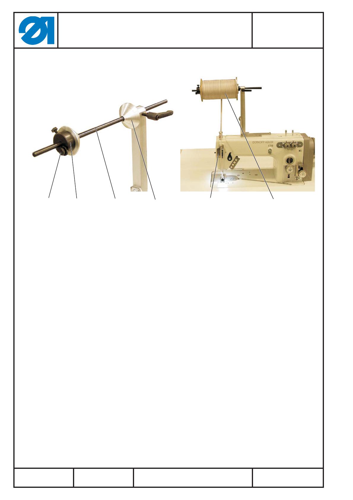
3.4 Setting the adjustment ring of the reinforcement tape roller support
The r einforcement tape roller 5 should be aligned centred to the
reinforcement tape guide and the needle.
Removethebrakecone3fromtherod2.
Shift the roller 5 on the rod 2.
Shift the brake cone 3 on the rod.
Align the roller 5 to be centred to the guide 6.
Fasten the cone 1 on the right.
Shift the brske cone 3 on the left against the roll and fasten it.
3.5 Setting the brake for the reinforcement tape
The r einforcement tape roller should no longer be in motion after the
ending of the sewing process.
At the same time the reinforcement tape roller should not brake
intensely, otherwise a warp on the sewing material may occur.
Set the brake 4 on the left brake cone 3 accordingly.
65
43 2 1
3.6 Mounting the control panel
If the sewing machine is equipped with the optional control panel, it
is possible to fix the control panel with its bracket 1 to the tape roller
bracket 4 using the two screws 2 and 3 (M4x6H and M4x16H).
3.7 Mounting the sewing foot
The following sewing feet are available for the sewing of
reinforcement tapes:
·
2.0 mm tape width 0176 220304
·
3.0 mm tape width: 0176 220314
·
5.0 mm tape width: 0176 220324
Please mount the corresponding sewing foot.
Anbauanleitung Bandzuführung
für Teilesatz 0176 590034
Fitting Instructions Tape Feeder
Kit 0176 590034
Teile-Nr./ Part-No.:
0791 176701
Änderungsindex
Rev. index: 00.0
Ausgabe/Edition:
01.2009
Printed in Germany
Blatt: 11 von 12
Sheet: 11 from 12
43 2 1
Anbauanleitung Bandzuführung
für Teilesatz 0176 590034
Fitting Instructions Tape Feeder
Kit 0176 590034
Teile-Nr./ Part-No.:
0791 176701
Blatt: 12 von 12
Sheet: 12 from 12
Ausgabe/Edition:
01.2009
Änderungsindex
Rev. index: 00.0
Printed in Germany
For your notes:
  • Page 1 1
  • Page 2 2
  • Page 3 3
  • Page 4 4
  • Page 5 5
  • Page 6 6
  • Page 7 7
  • Page 8 8
  • Page 9 9
  • Page 10 10
  • Page 11 11
  • Page 12 12

DURKOPP ADLER 176 Benutzerhandbuch

Typ
Benutzerhandbuch

in anderen Sprachen