
Teile-Nr./ Part-No.:
0791 888701
Printed in Czech Republic
Ausgabe/Edition:
06.2011
1 Allgemeine Informationen
Anzuwenden bei M-Type Einnadelsäulenmaschinen.
Anwendung mit dem Kantenanschlag N800 080030.
1.1 Anbausatz
Der komplette Bausatz zum Einfassen mit der Bestellnummer
0888 200614 besteht aus folgenden Komponenten:
0888 200620 Halter
0888 220700 Anschlag
0888 200674 Halter
9202 002058 Zyl.Schr. (M4X6)
9202 001657 Zyl.Schr. (M3X6)
9202 002068 Zyl.Schr. (M4X8)
9202 002088 Zyl.Schr. (M4X12)
0888 200640 Führung
0888 230180 Halter
0888 200710 Ring
0888 200700 Halter
0888 200690 Führung
9205 101848 Gew.Stift (M4X4)
2 Bedienung und Funktion der Einrichtung
2.1 Beschreibung
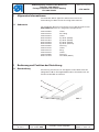
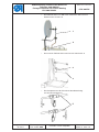
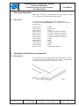
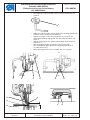
Einrichtung zum Einfassen ermöglicht an die Rückseite der
Nähgutkante A ein Einlageband B und an die Vorderseite ein
Ziereinfassband C anzunähen.
Anbauanleitung französischer Einfassen
Teilesatz 0888 200614
Fitting Instructions for French Binding
Kit 0888 200614
Änderungsindex
Rev. index: 00.0
Blatt: von
Sheet: 1 from 16
C
A
B
Abb. 1

Die Einrichtung besteht aus der Ziereinfassbandführung 1, die
mit Nähgut-Druckkantenanschlag, Seitenanschlag und
Einlagebandzuführung 2 ausgestattet ist und eine komplette
modifizierte Stichplatte beinhaltet. Außerdem gehören noch zwei
Rollenhalter zu der Einrichtung. Der obere Rollenhalter 3 dient
zum Abrollen des Ziereinfassbands C und der untere
Rollenhalter 4 zum Abrollen des Einlagebands B.
Anbauanleitung französischer Einfassen
Teilesatz 0888 200614
Fitting Instructions for French Binding
Kit 0888 200614
Teile-Nr./ Part-No.:
0791 888701
Printed in Czech Republic
Ausgabe/Edition:
06.2011
Blatt: von
Sheet: 2 from 16
3
4
1
2

Teile-Nr./ Part-No.:
0791 888701
Printed in Czech Republic
Ausgabe/Edition:
06.2011
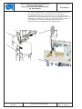
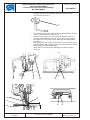
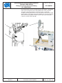
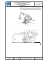
2.2 Vorgang beim Ziereinfassband- und Einlagebandannähen
–
Die Rolle mit dem oberen Ziereinfassband C auf den oberen
Rollenhalter 1 stecken, das Ziereinfassband über den
Führungsdraht 2 ziehen.
–
Das Ziereinfassband weiter durch die Führung ziehen 3 und
dort durch den Stellring 4 sicher n, so dass das
Ziereinfassband durch die Führung geht, aber nicht zu viel
Spiel hat.
–
An der Führung 6 die gleiche Einstellung mit Schraube 5
wiederholen.
– Die Rolle mit dem unterem Einlageband B auf den unteren
Rollenhalter stecken 7.
– Das Band durch das Loch in der Tischplatte durchziehen, in
die Führung einsetzen 8 und in die modifizierte Stichplatte
einschieben.
–
Dann den Einlageband durch das Loch im
Stichplatteneinsatz D mit dem Fingernagel bis zum
Nähpunkt schieben.
–
Die Kantenanschlage 6 und 9 müssen so eingestellt werden,
dass die Kanten des Nähguts A, des Einlagebandes B und
des Ziereinfassbandes C bündig liegen (siehe Abbildung 1
und Kapitel 3).
Anbauanleitung französischer Einfassen
Teilesatz 0888 200614
Fitting Instructions for French Binding
Kit 0888 200614
Änderungsindex
Rev. index: 00.0
Blatt: von
Sheet: 3 from 16
1
2
C
5
A
C
4
3
9
D
B
6
8
B
7

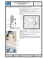
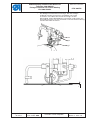
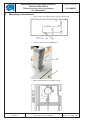
3 Einrichtungsmontage
–
Ein Loch in der Tischplatte für die Kunststoffbuchse
bohren 1.
–
Die Führung an der Mittelsäule anbringen 2.
–
Mit einem M6 Bohrer ein Loch in den Oberdeckel bohren.
Anbauanleitung französischer Einfassen
Teilesatz 0888 200614
Fitting Instructions for French Binding
Kit 0888 200614
Teile-Nr./ Part-No.:
0791 888701
Printed in Czech Republic
Ausgabe/Edition:
06.2011
Blatt: von
Sheet: 4 from 16
2
1

Teile-Nr./ Part-No.:
0791 888701
Printed in Czech Republic
Ausgabe/Edition:
06.2011
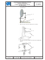
–
Den Rollenhalter 1 im M6 Loch montieren und mit einer
Kontermutter sichern 2.
–
Den unteren Rollenhalter 4 am Gestell montieren 3.
–
Die Komponenten der Ziereinfassbandzuführung
zusammenmontieren 5.
Anbauanleitung französischer Einfassen
Teilesatz 0888 200614
Fitting Instructions for French Binding
Kit 0888 200614
Änderungsindex
Rev. index: 00.0
Blatt: von
Sheet: 5 from 16
1
2
4
3
5

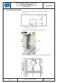
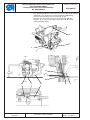
–
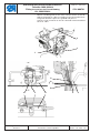
Die Komponenten des Nähgut-Druckkantenanschlags
zusammenmontieren 1.
–
Die montierten Teile der Ziereinfassbandzuführung 2 in das
Loch am Rollfußhalter einpassen 3.
–
Seitlich so justieren, dass die Nadel X möglichst nah zur
Ziereinfassbandführung steht 4, diese aber nicht anstößt.
–
Die Höhe des Kantenanschlags 4 gemäß der Nähgutdicke
justieren t.
–
Den Winkel der Führung 4 so einstellen, dass das Nähgut A,
das Einlageband B und das obere Ziereinfassband C seitlich
bündig liegen (siehe Abbildung 1).
–
Nach dem Justieren die Untergruppe mit der Schraube
sichern 5.
Anbauanleitung französischer Einfassen
Teilesatz 0888 200614
Fitting Instructions for French Binding
Kit 0888 200614
Teile-Nr./ Part-No.:
0791 888701
Printed in Czech Republic
Ausgabe/Edition:
06.2011
Blatt: von
Sheet: 6 from 16
1
29 35 4X
C
A
B
4
t
4X

Teile-Nr./ Part-No.:
0791 888701
Printed in Czech Republic
Ausgabe/Edition:
06.2011
–
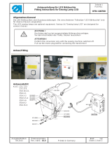
Der Nähgut-Druckkantenanschlag 1, der das Nähgut
andrückt und ein Verrutschen verhindert von hinten
anstecken. Die Höhe des Kantenanschlags mit der
Schraube 2 auf die Nähgutdicke t einstellen und seitlich auf
einen Abstand von 5,5 mm einstellen. Danach die Einstellung
mit der Schraube 3 sicher n.
Anbauanleitung französischer Einfassen
Teilesatz 0888 200614
Fitting Instructions for French Binding
Kit 0888 200614
Änderungsindex
Rev. index: 00.0
Blatt: von
Sheet: 7 from 16
3
2
1
t

–
Den abschwenkbaren Kantenanschlag 1 mit den Schrauben 2
anbringen. Den Kantenanschlag gemäß der Abbildung
seitlich zwischen den Kantenanschlag 3 und
Druckkantenanschlag justieren 4 und auf das Nähgut
bringen, dass alle zu nähenden Materialien A, B und C
seitlich bündig liegen.
Anbauanleitung französischer Einfassen
Teilesatz 0888 200614
Fitting Instructions for French Binding
Kit 0888 200614
Teile-Nr./ Part-No.:
0791 888701
Printed in Czech Republic
Ausgabe/Edition:
06.2011
Blatt: von
Sheet: 8 from 16
2
4
1
314 31
C
A
B

Teile-Nr./ Part-No.:
0791 888701
Printed in Czech Republic
Ausgabe/Edition:
06.2011
1 General information
Application on single needle postbed sewing machines M-Type.
It is used with the tiltable guide N800 080030.
1.1 Add-on Kit
The complete kit needed for the French binding has
the order number 0888 200614 and is made of the following
components:
0888 200620 Holder
0888 220700 Stop Guide
0888 200674 Holder
9202 002058 Cylinder Head Screw (M4X6)
9202 001657 Cylinder Head Screw (M3X6)
9202 002068 Cylinder Head Screw (M4X8)
9202 002088 Cylinder Head Screw (M4X12)
0888 200640 Guide
0888 230180 Holder
0888 200710 Ring
0888 200700 Holder
0888 200690 Guide
9205 101848 Threaded Pin (M4X4)
2 Operation and function of equipment
2.1 Description
The attachment for a binding tape stitching enables t o stitch
on a filler tape A on the back side of the sewn material B and
a decorative binding tape on the facial side C.
Anbauanleitung französischer Einfassen
Teilesatz 0888 200614
Fitting
Instructions for French Binding
Kit 0888 200614
Änderungsindex
Rev. index: 00.0
Blatt: von
Sheet: 9 from 16
C
A
B
Fig. 1

The attachment consists of a decorative tape guide 1 equipped
with a pressure guide and a side guide of the s ewn material
and with a filler tape guide 2, which includes a modified
complete throat plate. Parts of the attachment are also two tape
roller holders. The upper t ape roller holder 3 is used to unroll the
decorative binding tape C and the lower tape roller holder 4 is
used to unroll the filler tape B.
Anbauanleitung französischer Einfassen
Teilesatz 0888 200614
Fitting
Instructions for French Binding
Kit 0888 200614
Teile-Nr./ Part-No.:
0791 888701
Printed in Czech Republic
Ausgabe/Edition:
06.2011
Blatt: von
Sheet: 10 from 16
3
4
1
2

Teile-Nr./ Part-No.:
0791 888701
Printed in Czech Republic
Ausgabe/Edition:
06.2011
2.2 Process of binding tape and filler tape stitching
–
Put the roll with the upper decorative binding t ape C on the
upper tape roll holder 1 and pull the binding tape over the
guide rib 2.
–
Then pull the binding tape through the guide 3,whereby
means of a stop ring 4 ensure that the binding tape runs
through the guide, but is not very loose.
–
Repeat the same setting by means of the screw 5 in the
guide 6.
– Put the roll with the lower filler tape B on the lower tape roll
holder 7.
– Pull the binding tape through the hole in the tabletop, put it
into the guide 8 and slide it into the special throat plate.
–
Push the filler tape with your nail through the hole D in the
throat plate insert up to the stitching point.
–
The guide edges 6 and 9 must be set so that the edges of the
sewn material A, filler tape B and binding tape C flush (see
Fig. 1 and Chapter 3).
Anbauanleitung französischer Einfassen
Teilesatz 0888 200614
Fitting
Instructions for French Binding
Kit 0888 200614
Änderungsindex
Rev. index: 00.0
Blatt: von
Sheet: 11 from 16
1
2
C
5
A
C
4
3
9
D
B
6
8
B
7

3 Mounting of attachment
–
Drill a hole in the table top for a plastic bushing 1 .
–
Fit the guide 2 to the middle post.
–
Bore a M6 thread on the upper cover.
Anbauanleitung französischer Einfassen
Teilesatz 0888 200614
Fitting
Instructions for French Binding
Kit 0888 200614
Teile-Nr./ Part-No.:
0791 888701
Printed in Czech Republic
Ausgabe/Edition:
06.2011
Blatt: von
Sheet: 12 from 16
2
1

Teile-Nr./ Part-No.:
0791 888701
Printed in Czech Republic
Ausgabe/Edition:
06.2011
–
Fit the upper tape roll holder 1 in the M6 hole and fasten with
a counternut 2.
–
Mount the lower tape roll holder 4 on the stand 3.
–
Assemble the sub-assembly of the decorative binding tape
guide 5.
Anbauanleitung französischer Einfassen
Teilesatz 0888 200614
Fitting
Instructions for French Binding
Kit 0888 200614
Änderungsindex
Rev. index: 00.0
Blatt: von
Sheet: 13 from 16
1
2
4
3
5

–
Assemble the sub-assembly of the sewn material presser
guide 1.
–
Slide the sub-assembly of the decorative binding tape 2 into
the hole of the roller presser holder 3.
–
Adjust the sides so that the needle X is as close to the
decorative binding tape guide 4 as possible, but does not
strike it.
–
Adjust the height of the guide 4 according to the material
thickness t.
–
Set the guide 4 angle so that the sewn material A,
filler tape B and upper decorative binding tape C flus h
on sides (see Fig.1).
–
After adjusting fasten the assembly with the screw 5.
Anbauanleitung französischer Einfassen
Teilesatz 0888 200614
Fitting
Instructions for French Binding
Kit 0888 200614
Teile-Nr./ Part-No.:
0791 888701
Printed in Czech Republic
Ausgabe/Edition:
06.2011
Blatt: von
Sheet: 14 from 16
1
29 35 4X
C
A
B
4
t
4X

Teile-Nr./ Part-No.:
0791 888701
Printed in Czech Republic
Ausgabe/Edition:
06.2011
–
Put on from behind the sewn material pressure guide 1,
which presses down the sewn material, preventing it from
any raising up. Adjust the guide height with the screw 2 to
the sewn material thickness t and the sides to the distance
of 5.5 mm. After adjusting fasten with the screw 3.
Anbauanleitung französischer Einfassen
Teilesatz 0888 200614
Fitting
Instructions for French Binding
Kit 0888 200614
Änderungsindex
Rev. index: 00.0
Blatt: von
Sheet: 15 from 16
3
2
1
t

–
Mount a tiltable guide of the sewn material 1 with screws 2.
Adjust the guide on sides according to the picture between
the guide 3 and the pressure guide 4 and push it
onto the sewn material so that all stitched materials A, B, C
flushonsides.
Anbauanleitung französischer Einfassen
Teilesatz 0888 200614
Fitting
Instructions for French Binding
Kit 0888 200614
Teile-Nr./ Part-No.:
0791 888701
Printed in Czech Republic
Ausgabe/Edition:
06.2011
Blatt: von
Sheet: 16 from 16
2
4
1
314 31
C
A
B
-
 1
1
-
 2
2
-
 3
3
-
 4
4
-
 5
5
-
 6
6
-
 7
7
-
 8
8
-
 9
9
-
 10
10
-
 11
11
-
 12
12
-
 13
13
-
 14
14
-
 15
15
-
 16
16


in anderen Sprachen
- English: DURKOPP ADLER 888 User manual
Verwandte Artikel
-
DURKOPP ADLER 550-867 s Benutzerhandbuch
-
-
Duerkopp Adler 867-M Benutzerhandbuch
-
DURKOPP ADLER 580 Benutzerhandbuch
-
-
 Duerkopp Adler 550-2-2 Benutzerhandbuch
-
-
DURKOPP ADLER 175 Benutzerhandbuch
-
-

