Nodon ZIGBEE MULTIFUNCTION RELAY SWITCH Benutzerhandbuch
- Typ
- Benutzerhandbuch

ON
ON
ON
INSTALLATION - STECKDOSE
IMPULSMODUS
Es ist wichtig, den Impulsmodus zu aktivieren, bevor Sie das Modul
mit Ihrem Gateway koppeln, um das Tor / Garagentor zu steuern,
die angeschlossenen Geräte könnten beschädigt werden.
Das Modul muss mit Strom versorgt sein.
1 Schalten Sie die Stromversorgung ab.
2 Öffnen Sie die Steuerung der Tür / Garagentor etc.
3 Verkabeln sie das Multifunktionsmodul parallel wie
in Bild 1.
4 Bauen Sie die Steuerung der Tür / Garagentor wieder
zusammen.
5 Schalten den Strom wieder ein.
Achtung : Aktivieren SIe den Impulsmodus.
(siehe Abschnitt Impulsmodus) vor dem Pairing,
da sonst das angeschlossene Gerät Schaden
nehmen könnte..
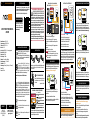
Bild 3
1 Schalten Sie den Strom ab.
2 Öffnen Sie die notwendigen Abdeckungen.
3 Verkabeln Sie das Multifunktionsmodul nach Bild 3,
achten Sie darauf die Steuerdrähte des Raumthermostats
anzuschliessen. (siehe Geräteanleitung).
4 Schließen Sie das Gerät wieder vollständig.
5 Schalten Sie den Strom wieder ein.
Bild 2
1 Schalten Sie die Stromversorgung ab.
2 Entfernen Sie die Steckdosenabdeckung.
3 Verkabeln Sie das Modul wie in Bild 2.
4 Bauen Sie wieder alles zusammen.
5 Schalten Sie den Strom wieder ein.
1 Drücken Sie 5x schnell den Knopf am Modul. Die
LED wird grün und bestätigt somit die Aktivierung des
Impulsmodus.
2 Sie können mit der Installation fortfahren.
SELBSTERKENNUNG DES SCHALTERTYPS
Wenn Sie die Stromversorgung (z. B. über den Stromkasten) wieder
einschalten, sobald das Modul fertig installiert ist, ist es notwendig,
eine einfache Aktion (eine einzelne Benutzung) am kabelgebundenen
Schalter vorzunehmen. Eine automatische Erkennung des
Schaltertyps (Taster oder Schalter) wird dann durchgeführt
INSTALLATION - TÜR / GARAGENTOR /
ELEKTR.HOFTOR- BINÄRER IMPULSKONTAKT
INSTALLATION - HEIZKESSEL - BINÄREINGANG
Hinweis : Um den Impulsmodus zu deaktivieren, drücken Sie
wieder 5x schnell auf den Knopf am Modul.
INSTALLATION
Herstellernummer : SIN-4-1-20
Stromversorgung : 230V AC ~ 50Hz
Schaltstrom : 230V AC - 16A
Verbrauch : <5W
Leistung Max. : 3680W – Zero Crossing integriert
Funkprotokoll : Zigbee 3.0
Frequenzband : 2,4Ghz
Funkstrahlung : +10dBm
Reichweite : Bis zu 40m im Gebäude
Betriebstemperatur : -20°C bis 60°C
Schutzklasse : IP 20
Abmessungen : 40 mm (l) x 44 mm (L) x 16.9 mm (h)
Gewicht : 34 g
Garantie : 2 Jahre
EINGÄNGE / AUSGÄNGE DES MODULS
Dank seiner geringen Größe kann das Multifunktionsmodul
in einer Unterputzdose, hinter Schaltern, Steckdosen etc.
verbaut werden.
Jede Klemme sollte an ein Kabel mit einem Querschnitt von >1,5mm²
bis <4mm² angeschlossen sein, Das Kabel sollte ca.8mm abisoliert sein.
*optionaler kabelgebundener Schalter
nodon.fr/de/ Abschnitt
“technische-unterstuetzung”
NodOn SAS
121 rue des Hêtres
45590 St CYR EN VAL
(FRANCE)
KONTAKT SUPPORT
GEBRAUCHSANWEISUNGDE
MULTIFUNKTIONSMODUL
ZIGBEE
Bauen Sie das Multifunktionsmodul in einen
Schaltschrank ein, mit der DIN Rail Box*
von Nodon. *optionales Zubehör
GEBRAUCHSANWEISUNG
Das Produkt sollte 20cm oder mehr vom Körper
entfernt genutzt werden.
Dieses Produkt entspricht dem Funkprotokoll
Zigbee.
Nur zum internen Gebrauch geeignet.
Das Vorhandensein dieses Symbols auf einem
Produkt zeigt an, dass es der europäischen Richtlinie
2012/19/EU entspricht. Informieren Sie sich über
die in Ihrer Region geltenden Bestimmungen
über die getrennte Sammlung von Elektro- und
Elektronikgeräten. Halten Sie sich an die lokalen Vorschriften
und entsorgen Sie das Produkt nicht mit gewöhnlichen
Haushaltsabfällen. Die richtige Entsorgung von Altprodukten
hilft, Umwelt und Gesundheit zu erhalten.
NodOnSAS erklärt, dass diese Funkanlage der
Richtlinie RED 2014/53/EU entspricht.
Den vollständigen Text der EU-Konformitätserklärung
finden Sie unter folgender Internetadresse: nodon.fr/de/
Abschnitt “technische-unterstuetzung“.
KONFORMITÄTSERKLÄRUNGEN
Sie können verschiedene Anschlußbeispiele auf unser Homepage
nden “technische-unterstuetzungt” auf nodon.fr/de/
ZURÜCKSETZEN DES MODULS
BITTE BEACHTEN
• Verwenden Sie das Gerät niemals, wenn es nicht
ordnungsgemäß installiert und/ oder in einer Anschlussbox
platziert ist, die den aktuellen Standards entspricht.
• Halten Sie das Produkt von Flüssigkeiten fern.
ANSCHLUSSPLÄNE
Bild 1
GEFAHR EINES STROMSCHLAGS
VOR INSTALLATION SICHER STELLEN, DASS
DIE STROMVERSORGUNG UNTERBROCHEN
IST. Schalten Sie die Stromversorgung direkt im
Schaltschrank aus, um die Gefahr eines Stromschlags
zu vermeiden. Dieses Modul ist für den elektrischen
Einsatz ausgelegt, eine unsachgemäße Installation
kann zu Feuer oder elektrischem Schlag führen. Wenn
Sie sich mit Elektroinstallationen nicht wohl fühlen,
wenden Sie sich bitte an einen Fachmann.
Die Installation und der Anschluss müssen nach den
Anweisungen in diesem Handbuch entsprechen.
Wir können nicht haftbar gemacht werden im Falle
eines Unfalls oder einer Beschädigung aufgrund der
Nichteinhaltung der Montageanleitung.
Schalten Sie die Stromversorgung vor jedem Eingriff aus und
nehmen Sie keine Änderungen vor, wenn die LED leuchtet.
VERBINDUNG MIT EINEM ZIGBEE NETZWERK
Bei der ersten in Betriebnahme blinkt die LED des Moduls orange
und kann somit an ein Zigbee-Netzwerk angelernt werden.
Aktivieren Sie die Inklusion am Zigbee fähigen Gateway, um die
Erkennung des Moduls zu starten. Liste der kompatiblen Gateways
nden Sie auf nodon.fr/de/technische-unterstuetzung/
Wenn das Modul richtig in das Netzwerk angelernt wurde,
leuchtet die LED grün. Das Modul kann jetzt genutzt werden.
Wenn das Modul nicht innerhalb von 15 Minuten mit einem
Netzwerk verbunden wurde, leuchtet die LED orange. Drücken
Sie die Taste des Moduls und wiederholen Sie den Vorgang.
NNeutralleiter
LPhase
Schaltereingang (I1)*
Unbenutzt
Eingangssignal das potentialfrei
durchgeschaltet werden soll
Ausgang des Signal
Gehen Sie direkt zur ausführlichen
Anleitung im Support Bereich
unter nodon.fr/de/technische-
unterstuetzung/
Hiermit erklärt NodOn SAS, dass dieses
Funkgerät der RER-Richtlinie 2017
(SI 2017/1206) entspricht. Der vollständige
Text der britischen Konformitätserklärung
ist unter der folgenden Internetadresse verfügbar:
nodon.fr/de/ Abschnitt “technische-unterstuetzung“.
HUTSCHIENENMONTAGE
Das Modul muß korrekt an der Stromversorgung
angeschlossen sein.
1 Drücken Sie die Taste des Moduls länger als 5 Sekunden bis
die LED orange leuchtet.
2 Drücken Sie die Taste einmal kurz um den Reset Prozess
zu starten. Wenn der Rücksetzungsprozess beginnt leuchtet
die LED rot.
3 Das Modul ist in den Auslieferungszustand zurück gesetzt worden
und kann jetzt an ein neues Zigbee Netzwerk angelernt werden.
EXKLUSION DES MODULS
Um das Modul aus dem Netzwerk zu entfernen, setzen Sie
dieses bitte in den Auslieferungszustand (siehe Modul-Reset-
Verfahren) zurück.
Anschrift des Importeurs in Großbritannien:
xxx
xxx

AUTO-DETECTION OF SWITCH TYPE
When you turn the power supply ON (via the electrical box for
example) once the relay switch is installed, it is necessary to
perform a simple action (single press on the button) on the wired
switch. Automatic detection of the type of switch (monostable or
bistable) will then be performed.
ON
ON
INSTALLATION
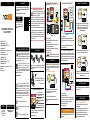
RELAY SWITCH INPUT/OUTPUT
nodon.fr/en/ “support” section
NodOn SAS
121 rue des Hêtres
45590 St CYR EN VAL
(FRANCE)
CONTACT AFTER-SALES SERVICE
USER GUIDEEN
The device is used 20 cm or more from the human
body.
This product is conform to Zibgee radio protocol.
This product must be used indoor only.
The presence of this symbol on a product
indicates that this one is conform to the
European directive 2012/19/UE. Find out
more about the provisions in force in your
region regarding the separate collection of electrical and
electronical devices. Respect the local rules and do not
throw out the product with common domestic wastes. The
correct rejection of ancient products allows to preserve
the environment and health.
Hereby, NodOn SAS declares that this radio
equipment is conform to the RED directive
2014/53/UE. The integral text of the EU declaration
of conformity is available at the following online address:
nodon.fr/en/ ”support” section.
APPROVALS AND CERTIFICATIONS
USE CAUTIONS
• Never use the device if it is not correctly installed and
placed inside a connecting box in conformity with the
current norms.
• Keep the product far away from liquids.
DANGER OF ELECTROCUTION
BEFORE ANY INSTALLATION MAKE SURE THE
POWER SUPPLY IS DISCONNECTED TO AVOID
ANY RISK OF ELECTROCUTION.
Directly cut the power supply from the breaker box to avoid
any risk of electrocution. This relay switch is designed to
be used power up, a wrong installation can create a re or
an electric shock. If you are not condent about electrical
installation, please ask a professional.
The relay switch must be installed and connected carefully
following the instructions of this user guide. We will not be
responsible for any loss or damage resulting from a non-
respect of the instructions of this user guide. Cut the power
supply before any operation and don’t do any modication
if the LED is still ON.
Reference: SIN-4-1-20
Power supply: 230V AC ~ 50Hz
Switching capabilities: 230V AC - 16A
Consumption: <5W
Max. Power: 3680W - Integrated Zero crossing
RF Protocol: Zigbee 3.0
Radio frequency range: 2.4Ghz
RF power Max: +10dBm
Range: up to 40m indoor
Operational temperature: -20°C to 60°C
Protection rating: IP 20
Dimensions: 40 mm (l) x 44 mm (L) x 16.9 mm (h)
Weight: 34 g
Warranty: 2 years
ZIGBEE MULTIFUNCTION
RELAY SWITCH
Each terminal should be installed with a cable from 1.5mm² to
4mm² maximum, stripped of 8mm.
*Wired switch optional.
ON
INSTALLATION - ELECTRICAL OUTLET
IMPULSE MODE
It is imperative to activate the impulse mode before pairing
your module to your home automation gateway to control
your gate/garage door/electric latch to avoid damaging
your equipment.
Relay switch must be power supplied.
1 Cut the power supply
2 Disassemble the push-button which controls the gate/
garage door/electric latch.
3 Wire the Multifunction Relay Switch, in parallel to the push-
button following the diagram gure 1.
4 Reassemble the push-button which controls the gate/
garage door/electric latch.
5 Turn the power back ON.
Warning: Activate the implulse mode (see the section)
before pairing to avoid any damage of your equipment.
Figure 3
1 Cut the power supply.
2 Disassemble the cable outlet.
3 Wire the Multifunction Relay Switch following the diagram
gure 3, making sure to connect the two wires which controls
the ambient thermostat (see your boiler user guide).
4 Reassemble the cable outlet.
5 Turn the power back ON.
Figure 2
1 Cut the power supply.
2 Disassemble the electrical outlet and the wall switch.
3 Wire the Multifunction Relay Switch, following the diagram
gure 2.
4 Reassemble the electrical outlet and the wall switch.
5 Turn the power back ON.
1 Do 5 brief presses on the button of the relay switch.
The LED pulses in green, conrming the activation
of the control access mode.
2 You can continue the installation procedure.
Thanks to its compact size, the Multifunction Relay Switch
can be installed behind a wall switch, an electrical outlet or
a cable outlet.
Add the Multifunction Relay Switch to the
electric panel with NodOn DIN Rail Box*.
*Optional accessory
Find all the installation diagrams on the “support” section on
nodon.fr/en/
RESET PROCEDURE
INSTALLATION DIAGRAMS
Figure 1
TIP
Relay switch must be power supplied.
1 Press more than 5 seconds on your module’s button.
The Led blinks orange.
2 Press the button again (short press) to validate the reset.
If the reset is successful, the Led flashes red and green
alternately, then flashes orange. Repeat if necessary.
3 Your module has returned to its original conguration
and is ready to join a new Zigbee network.
UNPAIRING PROCEDURE
To remove the module from its network, perform a Module Reset
(see “Reset Procedure”).
SIN-4-1-20-UG-DE-V3
ADDING TO A ZIGBEE NETWORK
When power is turned ON, the relay switch Led will blink
orange, looking to join a Zigbee network. Go to your Zigbee
gateway app to activate the relay switch detection.
See the compatible home automation gateways on
nodon.fr/en/support/
If the relay switch has correctly joined the network, the Led
becomes green. The relay switch is ready for use.
If the relay switch hasn’t joined a network within 15 minutes,
the Led becomes orange. Do a brief press on the relay switch
button and start again.
INSTALLATION - GATE/GARAGE DOOR/
ELECTRIC LATCH - MPULSE MODE DRY CONTACT
Note: To deactivate the impulse mode, repeat a series of 5
short presses.
INSTALLATION - BOILER - HELD DRY CONTACT
Directly access the detailed user
guide on the Support section
on nodon.fr/en/technical-
support/
DETAILED
USER GUIDE
NTerminal for the Neutral
LTerminal for the Line
Input terminal for
the wired switch 1 (I1)*
Not used
Input terminal, the potential will
pass through the output terminal
Output terminal
Hereby, NodOn declares that the radio
equipment type direct current motor
controller is in compliance with RER 2017
(SI 2017/1206). The full text of the UK declaration
of conformity is available at the following internet address:
nodon.fr/en/ “support” section.
UK importer address:
xxx
xxx
-
 1
1
-
 2
2

