
INSTALLATION
Herstellernummer : SIN-4-2-20
Stromversorgung : 230V AC ~ 50Hz
Schaltstrom : 230V AC - 2 x 3A
Verbrauch : <5W
Schaltstrom Max. : 2 x 690W – Zero Crossing integriert
Funkprotokoll : Zigbee 3.0
Frequenzband : 2,4Ghz
Funkstrahlung : +10dBm
Reichweite : bis zu 40m im Gebäude
Betriebstemperatur : -20°C bis 60°C
Schutzklasse : IP 20
Abmessungen : 40 mm (l) x 44 mm (L) x 16.9 mm (h)
Gewicht : 34 g
Garantie : 2 Jahre
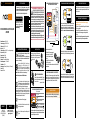
EINGÄNGE/ AUSGÄNGE DES MODULS
Dank seiner geringen Größe kann das
Zigbee Modul überall eingebaut werden,
im Schaltschrank, in der Unterputzdose
oder direkt an der
Lampe.
Jede Klemme sollte an ein Kabel mit einem Querschnitt von >1,5mm²
bis <4mm² angeschlossen sein, Das Kabel sollte ca.8mm abisoliert sein.
*optionaler kabelgebundener Schalter
nodon.fr/de/ Abschnitt
“technische-unterstuetzung”
NodOn SAS
121 rue des Hêtres
45590 St CYR EN VAL
(FRANCE)
KONTAKT SUPPORT
GEBRAUCHSANWEISUNGDE
SCHALTMODUL LICHT AN/AUS
ZIGBEE
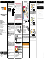
Bauen Sie das Schaltmodul AN/AUS Zigbee
in einen Schaltschrank ein, mit der DIN Rail
Box* von Nodon. *optionales Zubehör
Das Produkt sollte 20cm oder mehr vom Körper
entfernt genutzt werden.
Dieses Produkt entspricht dem Funkprotokoll
Zigbee.
Nur zum internen Gebrauch geeignet.
Das Vorhandensein dieses Symbols auf einem
Produkt zeigt an, dass es der europäischen Richtlinie
2012/19/EU entspricht. Informieren Sie sich über
die in Ihrer Region geltenden Bestimmungen
über die getrennte Sammlung von Elektro- und
Elektronikgeräten. Halten Sie sich an die lokalen Vorschriften
und entsorgen Sie das Produkt nicht mit gewöhnlichen
Haushaltsabfällen. Die richtige Entsorgung von Altprodukten
hilft, Umwelt und Gesundheit zu erhalten.
NodOnSAS erklärt, dass diese Funkanlage der Richtlinie
RED 2014/53/EU entspricht.
Den vollständigen Text der EU-Konformitätserklärung
nden Sie unter folgender Internetadresse: nodon.fr/de/ Abschnitt
“technische-unterstuetzung“.
KONFORMITÄTSERKLÄRUNGEN
Sie können verschiedene Anschlußbeispiele auf unser Homepage
nden “technische-unterstuetzungt” auf nodon.fr/de/
BITTE BEACHTEN
• Verwenden Sie das Gerät niemals, wenn es nicht
ordnungsgemäß installiert und/ oder in einer Anschlussbox
platziert ist, die den aktuellen Standards entspricht.
• Halten Sie das Produkt von Flüssigkeiten fern.
ANSCHLUSSPLÄNE
GEFAHR EINES STROMSCHLAGS
VOR INSTALLATION SICHER STELLEN, DASS
DIE STROMVERSORGUNG UNTERBROCHEN
IST. Schalten Sie die Stromversorgung direkt im
Schaltschrank aus, um die Gefahr eines Stromschlags
zu vermeiden. Dieses Modul ist für den elektrischen
Einsatz ausgelegt, eine unsachgemäße Installation
kann zu Feuer oder elektrischem Schlag führen. Wenn
Sie sich mit Elektroinstallationen nicht wohl fühlen,
wenden Sie sich bitte an einen Fachmann.
Die Installation und der Anschluss müssen nach den
Anweisungen in diesem Handbuch entsprechen.
Wir können nicht haftbar gemacht werden im Falle
eines Unfalls oder einer Beschädigung aufgrund der
Nichteinhaltung der Montageanleitung.
Schalten Sie die Stromversorgung vor jedem Eingriff aus und
nehmen Sie keine Änderungen vor, wenn die LED leuchtet.
NNeutralleiter
LPhase
Eingangsignal Taster 1*
Eingangsignal Taster 2*
Ausgang 1 (kontrolliert von )
Ausgang 2 (kontrolliert von )
ZURÜCKSETZEN DES MODULS
VERBINDUNG MIT EINEM ZIGBEE NETZWERK
Bei der ersten in Betriebnahme blinkt die LED des Moduls orange
und kann somit an ein Zigbee-Netzwerk angelernt werden.
Aktivieren Sie die Inklusion am Zigbee fähigen Gateway, um die
Erkennung des Moduls zu starten. Liste der kompatiblen Gateways
nden Sie auf nodon.fr/de/technische-unterstuetzung/
Wenn das Modul richtig in das Netzwerk angelernt wurde,
leuchtet die LED grün. Das Modul kann jetzt genutzt werden.
Wenn das Modul nicht innerhalb von 15 Minuten mit einem
Netzwerk verbunden wurde, leuchtet die LED orange. Drücken
Sie die Taste des Moduls und wiederholen Sie den Vorgang.
Das Modul muß korrekt an der Stromversorgung
angeschlossen sein.
1 Drücken Sie die Taste des Moduls länger als 5 Sekunden bis
die LED orange leuchtet.
2 Drücken Sie die Taste einmal kurz um den Reset Prozess
zu starten. Wenn der Rücksetzungsprozess beginnt leuchtet
die LED rot.
3 Das Modul ist in den Auslieferungszustand zurück gesetzt worden
und kann jetzt an ein neues Zigbee Netzwerk angelernt werden.
EXKLUSION DES MODULS
Um das Modul aus dem Netzwerk zu entfernen, setzen Sie
dieses bitte in den Auslieferungszustand (siehe Modul-Reset-
Verfahren) zurück.
Gehen Sie direkt zur ausführlichen
Anleitung im Support Bereich
unter nodon.fr/de/technische-
unterstuetzung/
GEBRAUCHSANWEISUNG
Hiermit erklärt NodOn SAS, dass dieses
Funkgerät der RER-Richtlinie 2017
(SI 2017/1206) entspricht. Der vollständige
Text der britischen Konformitätserklärung
ist unter der folgenden Internetadresse verfügbar:
nodon.fr/de/ Abschnitt “technische-unterstuetzung“.
ANSCHLUSSPLAN FÜR DIE INSTALLATION
VON EINER ODER ZWEI LAMPEN
Verkabelung von einer oder zwei Lampen
*Optional verkabelter Schalter.
*
1 Schalten Sie die Stromversorgung ab
2 Demontieren Sie den Schalter
den Sie in das Funknetz integrieren
möchten.
3 Verkabeln Sie das Funkmodul wie
es in Bild 1 zu sehen ist.
4 Bauen Sie den Schalter wieder ein und schalten Sie den
Strom wieder an.
Bild 1
SELBSTERKENNUNG DES SCHALTERTYPS
Nachdem Sie die Stromversorgung wieder hergestellt haben,
drücken Sie bitte den angeschlossenen Taster einmal. Das
Modul verfügt über eine automatische Erkennung über die Art
des angeschlossenen Schalters (Taster oder Schalter).
HUTSCHIENENMONTAGE
Anschrift des Importeurs in Großbritannien:
xxx
xxx

Each terminal should be installed with a cable from 1.5mm² to
4mm² maximum, stripped of 8mm.
*Wired switch optional.
NTerminal for the Neutral
LTerminal for the Line
Input terminal
for the wired switch 1*
Input terminal
for the wired switch 2*
Output 1 (controlled by )
Output 2 (controlled by )
INSTALLATION DIAGRAM
FOR ONE OR TWO LIGHTS
Wiring with one or two ways
*Wired switch optional.
*
1 Cut the power supply
2 Dismantle the wired switch
controlling the light(s) you want
to connect.
3 Install the ON/OFF Lighting Relay
Switch according to diagram gure 1.
4 Reinstall the wired switch.
5 Turn the power supply back ON.
Figure 1
INSTALLATION
RELAY SWITCH INPUT/OUTPUT
nodon.fr/en/ “support” section
NodOn SAS
121 rue des Hêtres
45590 St CYR EN VAL
(FRANCE)
CONTACT AFTER-SALES SERVICE
USER GUIDEEN
The device is used 20 cm or more from the human
body.
This product is conform to Zigbee radio protocol.
This product must be used indoor only.
The presence of this symbol on a product
indicates that this one is conform to the
European directive 2012/19/UE. Find out
more about the provisions in force in your
region regarding the separate collection of electrical and
electronical devices. Respect the local rules and do not
throw out the product with common domestic wastes. The
correct rejection of ancient products allows to preserve
the environment and health.
Hereby, NodOn SAS declares that this radio
equipment is conform to the RED directive
2014/53/EU. The integral text of the EU declaration
of conformity is available at the following online address:
nodon.fr/en/ ”support” section.
APPROVALS AND CERTIFICATIONS
USE CAUTIONS
• Never use the device if it is not correctly installed and
placed inside a connecting box in conformity with the
current norms.
• Keep the product far away from liquids.
DANGER OF ELECTROCUTION
BEFORE ANY INSTALLATION MAKE SURE THE
POWER SUPPLY IS DISCONNECTED TO AVOID
ANY RISK OF ELECTROCUTION.
Directly cut the power supply from the breaker box to avoid
any risk of electrocution. This relay switch is designed to
be used power up, a wrong installation can create a re or
an electric shock. If you are not condent about electrical
installation, please ask a professional.
The relay switch must be installed and connected carefully
following the instructions of this user guide. We will not be
responsible for any loss or damage resulting from a non-
respect of the instructions of this user guide. Cut the power
supply before any operation and don’t do any modication
if the LED is still ON.
Reference: SIN-4-2-20
Power supply: 230V AC ~ 50Hz
Switching capabilities: 230V AC - 2 x 3A
Consumption: <5W
Maximum output power: 2 x 690W - Integrated zero crossing
RF Protocol: Zigbee 3.0
Radio frequency range: 2.4Ghz
RF power max: +10dBm
Range: up to 40m indoor
Operational temperature: -20°C to 60°C
Protection rating: IP 20
Dimensions: 40 mm (l) x 44 mm (L) x 16.9 mm (h)
Weight: 34 g
Warranty: 2 years
ZIGBEE ON/OFF LIGHTING
RELAY SWITCH
Add the Zigbee ON/OFF Lighting Relay
Switch to the electric panel with NodOn
DIN Rail Box*.*Optional accessory
Find all the installation diagrams on the “Support” section on
nodon.fr/en/
INSTALLATION DIAGRAMS
TIP
SIN-4-2-20_UG_DE_V3
Thanks to its small size, the Zigbee ON/
OFF Lighting Relay Switch can be installed
anywhere in the wall or the ceiling (behind
an existing wall
switch, in a false
ceiling, etc…).
RESET PROCEDURE
Relay switch must be power supplied.
1 Press more than 5 seconds on your module’s button.
The Led blinks orange.
2 Press the button again (short press) to validate the reset.
If the reset is successful, the Led flashes red and green
alternately, then flashes orange. Repeat if necessary.
3 Your module has returned to its original conguration
and is ready to join a new Zigbee network.
UNPAIRING PROCEDURE
To remove the module from its network, perform a Module Reset
(see “Reset Procedure”).
ADDING TO A ZIGBEE NETWORK
When power is turned ON, the relay switch Led will blink
orange, looking to join a Zigbee network. Go to your Zigbee
gateway app to activate the relay switch detection.
See the compatible home automation gateways on
nodon.fr/en/support/
If the relay switch has correctly joined the network, the Led
becomes green. The relay switch is ready for use.
If the relay switch hasn’t joined a network within 15 minutes,
the Led becomes orange. Do a brief press on the relay switch
button and start again.
Directly access the detailed user
guide on the Support section
on nodon.fr/en/technical-
support/
DETAILED
USER GUIDE
AUTO-DETECTION OF SWITCH TYPE
When you turn the power supply ON (via the electrical box for
example) once the relay switch is installed, it is necessary to
perform a simple action (single press on the button) on the
wired switch(es). Automatic detection of the type of switch
(monostable or bistable) will then be performed.
Hereby, NodOn declares that the radio
equipment type direct current motor
controller is in compliance with RER 2017
(SI 2017/1206). The full text of the UK declaration
of conformity is available at the following internet address:
nodon.fr/en/ “support” section.
UK importer address:
xxx
xxx
-
 1
1
-
 2
2


in anderen Sprachen
- English: Nodon SIN-4-2-20 User guide
Verwandte Artikel

Andere Dokumente
-
Niko 552-721X1 Benutzerhandbuch
-
-
Niko 552-722X1 Benutzerhandbuch
-
Carel WS01RB2M Series Schnellstartanleitung
-
Gewiss Chorusmart Connected Axial 2-Command Module Benutzerhandbuch
-
Aqara SSM-U01 Benutzerhandbuch
-
SVL 1006457 Bedienungsanleitung
-
Dell Edge Gateway 3000 Series Benutzerhandbuch
-