
N L
N L
N L
N L
INSTALLATION
nodon.fr/de/ Abschnitt
“technische-unterstuetzung”
NodOn SAS
121 rue des Hêtres
45590 St CYR EN VAL
(FRANCE)
KONTAKT SUPPORT
GEBRAUCHSANWEISUNGDE KONFORMITÄTSERKLÄRUNGEN
BITTE BEACHTEN
• Verwenden Sie das Gerät niemals, wenn es nicht
ordnungsgemäß installiert und/ oder in einer Anschlussbox
platziert ist, die den aktuellen Standards entspricht.
• Halten Sie das Produkt von Flüssigkeiten fern.
GEFAHR EINES STROMSCHLAGS
VOR INSTALLATION SICHER STELLEN, DASS
DIE STROMVERSORGUNG UNTERBROCHEN
IST. Schalten Sie die Stromversorgung direkt im
Schaltschrank aus, um die Gefahr eines Stromschlags
zu vermeiden. Dieses Modul ist für den elektrischen
Einsatz ausgelegt, eine unsachgemäße Installation
kann zu Feuer oder elektrischem Schlag führen. Wenn
Sie sich mit Elektroinstallationen nicht wohl fühlen,
wenden Sie sich bitte an einen Fachmann.
Die Installation und der Anschluss müssen nach den
Anweisungen in diesem Handbuch entsprechen.
Wir können nicht haftbar gemacht werden im Falle
eines Unfalls oder einer Beschädigung aufgrund der
Nichteinhaltung der Montageanleitung.
Schalten Sie die Stromversorgung vor jedem Eingriff
aus und nehmen Sie keine Änderungen vor, wenn die
LED leuchtet.
ROLLLADENMODUL
Dieses Produkt entspricht dem Funkprotokoll
EnOcean.
Nur zum internen Gebrauch geeignet.
Dieses Symbol auf einem Produkt bedeutet, dass
letzteres der europäischen Richtlinie 2012/19/EU
entspricht. Informieren Sie sich über die in Ihrer Region
geltenden Bestimmungen was die Getrenntsammlung
elektrischer und elektronischer Geräte anbelangt. Beachten Sie die
örtlichen Vorschriften und entsorgen Sie das Produkt nicht mit dem
üblichen Hausmüll. Die korrekte Entsorgung alter Produkte trägt
zum Umwelt- und Gesundheitsschutz bei.
Hiermit bestätigt NodOn SAS , dass dieses
Gerät der Richtlinie RED 2014/53/EU entspricht.
Der vollständige Text der CE-Konformitätserklärung
ist auf folgender Webseite verfügbar: nodon.fr/de/ Abschnitt
“technische-unterstuetzung“.
VERWENDUNG DES SOFT-BUTTONS
Der Soft-Button funktioniert folgendermaßen:
RESET-VERFAHREN FÜR DAS MODUL
Weitere Informationen zur Kopplung
mit einer Haustechnikzentrale und
zu anderen kompatiblen Produkten
nden Sie in der Rubrik “technische-
unterstuetz” auf nodon.fr/de/
ENTKOPPLUNG
DES ROLLLADENMODULS
KOPPLUNG MIT EINER
HAUSTECHNIKZENTRALE
Artikelnummer: SIN-2-RS-XX
Spannungsversorgung: 230V AC ~ 50Hz
Schaltfähigkeit: 230V AC - 3A
Verbrauch: <1W
Maximale Motorleistung: Max. 280W - Max. 60 Nm
Liste der kompatiblen Motoren verfügbar auf nodon.fr/loads
Verwendete Funkfrequenzbänder: 868,0 bis 868,6 Mhz
Maximale Sendeleistung: +3dBm
Tragweite: Bis zu 30m in Innenräumen
Betriebstemperatur: -10°C bis 40°C
Schutzart: IP 30
Kopplung: bis zu 22 Controller
EEP (Prol EnOcean): D2-05-00
Abmessungen: 40 mm (B) x 44 mm (L) x 16,9 mm (H)
Gewicht: 34 g
Garantie: 2 Jahre
Dank seiner geringen Größe kann das Rollladenmodul in einem
Anschlusskasten oder hinter dem Schalter installiert werden, der
den Rollladen oder die motorisierte Markise steuert.
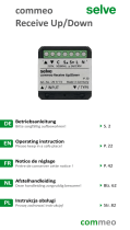
Bauen Sie das Rollladenmodul in einen
Schaltschrank ein, mit der DIN Rail Box* von
Nodon. *optionales Zubehör
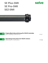
NEingang Neutralleiter
LEingang Phase
Eingang drahtgebundener Schalter
„Aufwärts“*
Eingang drahtgebundener Schalter
„Abwärts“*
Ausgang Motor „Aufwärts“
Ausgang Motor „Abwärts“
EINGÄNGE / AUSGÄNGE DES MODULS
Jede Klemme sollte an ein Kabel mit einem Querschnitt von >1,5mm²
bis <4mm² angeschlossen sein, Das Kabel sollte ca.8mm abisoliert sein.
*Optionaler drahtgebundener Schalter
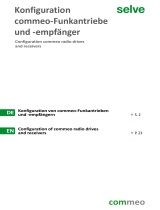
ANSCHLUSSPLAN
SELBSTERKENNUNG DES SCHALTERTYPS
Nachdem Sie den Strom wieder eingeschaltet haben,
drücken Sie auf die Taste Ihres drahtgebundenen
Schalters, bis der Rollladen auf halber Höhe steht.
Das Modul weist ein automatisches Erkennungssystem auf, das
den Typ des am Eingang verdrahteten drahtgebundenen Schalters
(Wechseltastschalter oder Druckschalter) erkennt.
*Verkabelter Taster optional
*
Bild 1
Anschlussklemme
KALIBRIERUNG
Hinweis: Die LED des
Moduls blinkt grün.
Dies zeigt an, dass die
Kalibrierung begonnen hat.
1 Fünfmal kurz drücken.
2/3 Der Rollladen oder die Markise
führt einen Zyklus „aufwärts/
abwärts/aufwärts“ durch **.
** Sollte der Zyklus
umgekehrt ablaufen
(abwärts/aufwärts/
abwärts), kehren Sie
und um
1 Bringen Sie den
Rollladen/die Markise in die
angehobene Position.
2 Führen Sie dreimal die
Sequenz „Oben - Stopp“
mit dem drahtgebundenen
Schalter durch.
Kalibrierung
abbrechen: Drücken
Sie fünfmal kurz auf
das verbundene Modul
oder einmal auf den
drahtgebundenen
Schalter.
KOPPLUNG DES ROLLLADENMODULS
Fernbedienung oder Schalter:
Sie haben 30 Sekunden Zeit, um Ihren Controller zu koppeln, indem
Sie kurz auf eine Taste Ihrer Wahl drücken (weniger als eine Sekunde).
Dadurch wird die Aufwärtsbewegung Ihres Rollladens/Ihrer
Markise gesteuert.
Ou
Ou
4 Fernbedienung oder Schalter:
Sie haben 30 Sekunden Zeit, um Ihren Controller zu koppeln,
indem Sie auf eine Taste Ihrer Wahl drücken (weniger als
eine Sekunde). Dadurch wird die Aufwärtsbewegung Ihres
Rollladens/Ihrer Gelenkarmmarkise gesteuert.
5 Der Rollladen/die Markise
bestätigt die Kopplung, indem
er/sie sich vollständig schließt.
3 Der Rollladen/die
Markise fährt um 10 %
nach oben.
2 Führen Sie dreimal die
Sequenz „Unten - Stopp“
mit dem drahtgebundenen
Schalter durch.
1 Bringen Sie den
Rollladen/die Markise
in die abgesenkte
Position.
Oder
Oder
Gehen Sie direkt zur ausführlichen
Anleitung im Support Bereich
unter nodon.fr/de/technische-
unterstuetzung/
GEBRAUCHSANWEISUNG
SIN-2-RS-01-UG_DE-V3
Arten der Betätigung Aktion
Ein Mal drücken Umschalten
Zwei Mal drücken Offen
Lange drücken Geschlossen
Das Modul muss angeschlossen und eingeschaltet sein.
1 Drücken Sie mehr als 5 Sekunden lang auf die Taste des
Moduls. Die LED blinkt orange.
2 Drücken Sie erneut auf die Taste (kurzes Drücken), um den
Reset zu bestätigen. Wird der Reset erfolgreich durchgeführt,
blinkt die LED abwechselnd rot und grün und wird dann wieder
grün. Wiederholen Sie gegebenenfalls den Vorgang.
3 Ihr Modul bendet sich wieder in seiner ursprünglichen
Einstellung.
Führen Sie dasselbe Verfahren wie bei der Kopplung durch
(siehe „Kopplung des Rollladenmoduls“), wobei Sie auf die zuvor
ausgewählte Taste drücken müssen, um die Aufstieg von ihrem
Rollladen/ihrer Markise zu steuern.
1 Schalten Sie den Strom ab.
2 Demontieren Sie den drahtgebundenen Schalter, der
den Rollladen/die Markise steuert, den/die Sie anschließen
möchten.
3 Verdrahten Sie das Modul gemäß dem Schema der Abbildung 1.
4 Bauen Sie den drahtgebundenen Schalter wieder zusammen.
5 Schalten Sie den Strom wieder ein.
Hinweis: Für beide Eingänge ( und ) wird derselbe Aufbau
verwendet. Es ist nicht möglich, einen Wechseltastschalter mit
einem Druckschalter zu kombinieren. Um die automatische
Erkennung neu zu starten, muss das Rollladenmodul manuell
zurückgesetzt werden (siehe Reset-Verfahren für das Modul).
Das Modul muss angeschlossen und eingeschaltet sein.
Zwei Modi:
1. Vom verbundenen Modul aus
2. Vom drahtgebundenen Schalter aus
Um eine Fernbedienung / einen Schalter / einen Soft Button
(EnOcean Kompatibel) einzufügen, müssen Sie in den Pairing-
Modus gehen und ihre Beleuchtung ausschalten.
Das Modul muss angeschlossen und eingeschaltet sein.
Zwei Modi:
1. Vom verbundenen Modul aus
1 IStarten Sie die
Kopplung, indem
Sie schnell dreimal
hintereinander auf
die Taste des Moduls
drücken. Die LED
blinkt rot.
Hinweis: Wenn die LED während des Kopplungsverfahrens
orange blinkt, bedeutet dies, dass mehr als 22 Controller gekoppelt
sind und dass kein weiterer Controller mehr gekoppelt werden
kann. Sie müssen folglich einen Controller entfernen, um einen
neuen hinzufügen zu können.
3 Die LED des Moduls
blinkt zweimal grün, womit
die Kopplung der beiden
Geräte bestätigt wird.
Soft Button :
Sie haben 30 Sekunden Zeit, um
Ihren Soft-Button anzumelden,
indem Sie 5 Mal hintereinander
kurz auf Ihre Taste drücken.
2. Vom drahtgebundenen Schalter aus
HUTSCHIENENMONTAGE

N L
N L
N L
N L
USER GUIDEEN APPROVALS AND CERTIFICATIONS
INSTALLATION
APPROBATIONS ET CERTIFICATIONS
*
Figure 1
Or
Or
Or
Or
CONTACT AFTER SALES SERVICE
USE CAUTIONS
• Never use the device if it is not correctly installed and
placed inside a connecting box in conformity with the
current norms.
• Keep the product far away from liquids.
nodon.fr/en/ “support” section
NodOn SAS
121 rue des Hêtres
45590 St CYR EN VAL
(FRANCE)
This product is conform to EnOcean radio protocol.
This product must be used indoor only.
The presence of this symbol on a product indicates
that this one is conform to the European directive
2012/19/UE. Find out more about the provisions in
force in your region regarding the separate collection
of electrical and electronical devices. Respect the local rules and
do not throw out the product with common domestic wastes.
The correct rejection of ancient products allows to preserve the
environment and health.
Hereby, NodOn SAS declares that this radio equipment
is conform to the RED directive 2014/53/UE. The
integral text of the EU declaration of conformity
is available at the following online address: nodon.fr/en/
”support” section.
DANGER OF ELECTROCUTION
BEFORE ANY INSTALLATION MAKE SURE
THE POWER SUPPLY IS DISCONNECTED
TO AVOID ANY RISK OF ELECTROCUTION.
Directly cut the power supply from the breaker
box to avoid any risk of electrocution. This relay switch is
designed to be used power up, a wrong installation can
create a re or an electric shock. If you are not condent
about electrical installation, please ask a professional.
The relay switch must be installed and connected carefully
following the instructions of this user guide. We will not be
responsible for any loss or damage resulting from a non-
respect of the instructions of this user guide. Cut the power
supply before any operation and don’t do any modication
if the LED is still ON.
For more details on how to pair
a home automation gateway or
other compatible products, please
consult the “Support” section on
nodon.fr/en/
PAIRING
WITH A HOME AUTOMATION GATEWAY
UNPAIRING PROCEDURE
RESET PROCEDURE
DETAILED
USER GUIDE
Directly access the detailed user
guide on the Support section
on nodon.fr/en/technical-
support/
Types of press Action
Single press Reversal
Double press Open
Long press Closed
Do the same procedure as pairing (see “pairing procedure”) and
takes care of pressing the button chosen to control your gate/
garage door/electric latch or your electrical outlet.
Relay switch must be power supplied.
1 Press more than 5 seconds on your module’s button.
The LED blinks orange.
2 Press once again the button (short press) to conrm the
reset. If the reset is correct, the LED blinks alternatively in red
and green and stays green. Start again if necessary.
3 Your module has now its original settings.
TIP
Reference: SIN-2-RS-01
Power supply: 230V AC ~ 50Hz
Switching capabilities: 230V AC - 3A
Consumption: <1W
Maximum motor power: 280W Max - 60 Nm Max
List of compatible motors available on nodon.fr/loads
Radio frequency range: 868.0 to 868.6 Mhz
RF power Max: +3dBm
Range: up to 30m indoor
Operational temperature: -10°C to 40°C
Protection rating: IP 30
Pairing: up to 22 controllers
EEP (EnOcean Prole): D2-05-00
Dimension: 40 mm (l) x 44 mm (L) x 16,9 mm (h)
Weight: 34 g
Warranty: 2 years
ROLLER SHUTTER
RELAY SWITCH
Thanks to its compact size, the Roller Shutter Relay Switch can
be installed in a connecting box or behind the wall switch which
controls the roller shutter or motorized awning.
Add the Roller Shutter Relay Switch to the
electric panel with NodOn DIN Rail Box*.
*Optional accessory
RELAY SWITCH INPUT/OUTPUT
Each terminal can accept a cable of 2.5mm² maximum, stripped
of 8mm.
*Wired switch optional (see the installation diagrams section)
NTerminal for the Neutral
LTerminal for the Line
Input terminal for the wired
switch “up”*
Input terminal for the wired
switch “down”*
Motor output terminal “up”
Motor output terminal “down”
INSTALLATION DIAGRAM
*Wired switch optional (see the installation diagrams section)
Connection terminal
1 Cut the power supply.
2 Disassemble the wired wall switch which controls the roller
shutter/awning you want to connect.
3 Wire the Relay Switch according to the diagram gure 1.
4 Reassemble the wired wall switch.
5 Turn the power back ON.
AUTO-DETECTION OF SWITCH TYPE
After turning the power supply ON, do a single push on the
wired wall switch to bring the roller shutter half-height. The
Relay Switch has an auto-detection system to automatically
detect the type of wired wall switch (rocker or push-button)
wired at the input.
Note: The same conguration is applied for both inputs
( and ).It is not possible to combine a rocker switch
with a push-button. To perform a new auto-detection, the
Roller Shutter Relay Switch must be manually reset (see
reset procedure).
CALIBRATION
OF THE ROLLER SHUTTER RELAY SWITCH
Note:The Relay Switch LED
blinks green, meaning the
calibration has well started.
1 Do 5 short presses.
Relay Switch must be power supplied.
Two modes:
1. From the Relay Switch
1 Put the roller shutter/
awning in position up.
2 Do 3 times the cycle
”up - stop” with the wired
wall switch.
2. From the wired wall switch
2/3 The roller shutter/awning
conrms the auto-calibration by
performing a complete cycle
”up/down/up” **.
** If the cycle is reversed
(down/up/down), switch
and
Cancel the
calibration:
Perform 5 brief presses.
From the wired switch,
press once on the
switch.
PAIRING
THE ROLLER SHUTTER RELAY SWITCH
To add a remote or a wall switch or the Soft Button (EnOcean
compatible) you must enter the pairing mode, your light must be
switched OFF.
Relay Switch must be power supplied.
Two modes:
1. From the Relay Switch
1 Launch the pairing
by doing 3 consecutive
presses on the button
of the Relay Switch.
The LED blinks red.
Remote or wall switch:
You have now 30 seconds to pair your controller by briefly
pressing on the button of your choice (less than a second), this
one will control the rise of your roller shutter/awning.
Note: if the LED blinks orange during the pairing procedure, it
means that more than 22 controllers are paired and that no more
controller can be paired. You must remove one controller to add
a new one.
3 The Relay Switch
LED blinks twice green,
conrming the pairing.
Soft Button :
You have now 30 seconds
to pair your Soft Button by doing
5 brief consecutive presses on
the button.
2 Do 3 times the cycle
“down - stop” with the
wired wall switch.
1 Put the roller shutter/
awning on position
down.
2. From the wired wall switch
3 The roller shutter/
awning will rise of 10%.
4 Remote or wall switch:
You have 30 seconds to pair your controller by briefly pressing
the button of your choice (less then a second), this one will
control the rise of your roller shutter/awning.
5 The roller shutter/awning
conrms the pairing
by closing completely.
USE OF YOUR SOFT BUTTON
The Soft Button will work as follows:
-
 1
1
-
 2
2


in anderen Sprachen
- English: Nodon SIN-2-RS-01 User guide
Verwandte Artikel

Andere Dokumente
-
elero TempoTel 2 Operating Instructions Manual
-
Chamberlain CS8001 Bedienungsanleitung
-
 Selve Configuration commeo radio drives and receivers Bedienungsanleitung
-
PEHA Compact 952 JRM Operating Instructions Manual
-
 Selve commeo Receive Up/Down Bedienungsanleitung
-
 Selve SE Pro-SMI_SE Plus-SMI_SEZ-SMI Bedienungsanleitung


