Peavey XR 800F Benutzerhandbuch
- Kategorie
- Musikinstrumentenverstärker
- Typ
- Benutzerhandbuch
Dieses Handbuch ist auch geeignet für


Intended to alert the user to the presence of uninsulated “dangerous voltage” within the product’s
enclosure that may be of sufficient magnitude to constitute a risk of electric shock to persons.
Intended to alert the user of the presence of important operating and maintenance (servicing)
instructions in the literature accompanying the product.
CAUTION: Risk of electrical shock — DO NOT OPEN!
CAUTION: To reduce the risk of electric shock, do not remove cover. No user serviceable parts inside. Refer
servicing to qualified service personnel.
WARNING: To prevent electrical shock or fire hazard, do not expose this appliance to rain or moisture. Before
using this appliance, read the operating guide for further warnings.
Este símbolo tiene el propósito, de alertar al usuario de la presencia de “(voltaje) peligroso” sin ais-
lamiento dentro de la caja del producto y que puede tener una magnitud suficiente como para constituir
riesgo de descarga eléctrica.
Este símbolo tiene el propósito de alertar al usario de la presencia de instruccones importantes sobre la
operación y mantenimiento en la información que viene con el producto.
PRECAUCION: Riesgo de descarga eléctrica ¡NO ABRIR!
PRECAUCION: Para disminuír el riesgo de descarga eléctrica, no abra la cubierta. No hay piezas útiles dentro.
Deje todo mantenimiento en manos del personal técnico cualificado.
ADVERTENCIA: Para evitar descargas eléctricas o peligro de incendio, no deje expuesto a la lluvia o humedad
este aparato Antes de usar este aparato, Iea más advertencias en la guía de operación.
Ce symbole est utilisé dans ce manuel pour indiquer à l’utilisateur la présence d’une tension dangereuse
pouvant être d’amplitude suffisante pour constituer un risque de choc électrique.
Ce symbole est utilisé dans ce manuel pour indiquer à l’utilisateur qu’il ou qu’elle trouvera d’importantes
instructions concernant l’utilisation et l’entretien de l’appareil dans le paragraphe signalé.
ATTENTION: Risques de choc électrique — NE PAS OUVRIR!
ATTENTION: Afin de réduire le risque de choc électrique, ne pas enlever le couvercle. Il ne se trouve à l’intérieur
aucune pièce pouvant être reparée par l’utilisateur. Confiez I’entretien et la réparation de l’appareil à un réparateur
Peavey agréé.
AVERTISSEMENT: Afin de prévenir les risques de décharge électrique ou de feu, n’exposez pas cet appareil à la
pluie ou à l’humidité. Avant d’utiliser cet appareil, lisez attentivement les avertissements supplémentaires de ce
manuel.
Dieses Symbol soll den Anwender vor unisolierten gefährlichen Spannungen innerhalb des Gehäuses
warnen, die von Ausreichender Stärke sind, um einen elektrischen Schlag verursachen zu können.
Dieses Symbol soll den Benutzer auf wichtige Instruktionen in der Bedienungsanleitung aufmerksam
machen, die Handhabung und Wartung des Produkts betreffen.
VORSICHT: Risiko — Elektrischer Schlag! Nicht öffnen!
VORSICHT: Um das Risiko eines elektrischen Schlages zu vermeiden, nicht die Abdeckung enfernen. Es befinden
sich keine Teile darin, die vom Anwender repariert werden könnten. Reparaturen nur von qualifiziertem
Fachpersonal durchführen lassen.
ACHTUNG: Um einen elektrischen Schlag oder Feuergefahr zu vermeiden, sollte dieses Gerät nicht dem Regen
oder Feuchtigkeit ausgesetzt werden. Vor Inbetriebnahme unbedingt die Bedienungsanleitung lesen.
2

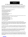
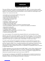
XR™800F Powered Sound Reinforcement Mixing Console
Congratulations on your purchase of the XR™800F powered mixer. Peavey has packed features
from the popular XR 684 into a professional 9-channel, tabletop package. The newest member of
the famous Peavey XR family, the XR 800F, represents years of powered mixer experience
combined with the latest in technology and packaging. Here are several features you will find on
the XR 800F.
• Eight low-noise, low-Z mic preamps (Channels 1-8)
• Six 1/4" line inputs (Channels 1-6)
• Three Stereo line inputs (Channels 7-9)
• 60 mm channel and master faders
• Channel clipping LEDs
• Channel stereo pan controls
• Three-band equalization (Channels 1-8)
• Monitor send (each channel)
• EFX send (each channel)
• 32-bit precision, DSP-based stereo effects processor with 16 presets and two parameter controls
• Two 9-band graphic EQs with FLS®Feedback Locating System®
• Selectable 48 V phantom power
• Dual seven segment master level meters
• Stereo/Main-monitor mode switch
• 2x210 W @ 4 ohms internal power amplifier
• 420 W @ 8 ohms in bridge mode
• DDT™speaker protection
The standard channels (1-6) feature discrete low noise mic preamps with globally switched
phantom power, line level 1/4" inputs, and three-band EQs. Finally, there are three stereo channels
(7-9) for tape, CD, or synth inputs. Channels 7 and 8 reflect Channels 1 through 6 with added stereo
1/4" input jacks. Channel 9, however, has a two-band EQ, no input gain control, and only stereo
tape input and output jacks.
The master section features a unique graphic equalizer/power amp mode switch. Without patching,
the XR 800F can be used as a full stereo mixer amplifier (default). In the Main/Monitor mode, one
graphic and amplifier can be used for monitor and the other graphic and amplifier for the main L and
R (mono) signal.
Also included in the master section are 16 stereo digital effects from the award winning Deltafex™
digital signal processor. By including separate time/size and color/tone controls, the user can
create many effect settings from the 16 we provided. All channels, including Channel 9, have a
dedicated digital effects send routed directly to the DSP effects processor.
To take advantage of the XR 800F’s powerful features, please read this owner’s manual carefully
and keep it as a reference. This manual includes several sections detailing individual areas of mixer
operation, including: control functions, setup, and applications in sound reinforcement. Before the
channel and master functions are explained, we will begin with connecting AC power and speakers
to the XR 800F.
ENGLISH
3

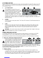
AC POWER SECTION
The AC POWER SECTION explains the proper connections/method to supply AC power to your XR
800F. Please pay close attention to the precaution(s) noted below in order to ensure both personal
and equipment safety.
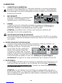
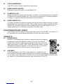
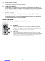
1. A/C POWER INLET:
This receptacle is for the IEC line cord
(included), which provides AC power to the
unit. Connect the line cord to this connector
and to a properly grounded AC supply.
Damage to the equipment may occur if an
improper line voltage is used. (See voltage
marking on unit.) Never remove or cut the ground pin of the line cord plug. This unit is
supplied with a properly rated line cord. When lost or damaged, replace this cord with one of
the proper ratings.
2. POWER:
This is the mixer’s main power switch. The Power LED indicator (21) will illuminate when the
unit is powered.
3. FUSE:
This is the main safety fuse for the AC line voltage. Only replace the fuse with one of the
exact same type and rating. IF THE FUSE CONTINUES TO OPEN, DO NOT REPLACE
WITH A LARGER FUSE. TAKE THE UNIT TO AN AUTHORIZED PEAVEY SERVICE
CENTER!
WARNING: THE FUSE SHOULD ONLY BE REPLACED WHEN THE POWER CORD HAS
BEEN DISCONNECTED FROM ITS POWER SOURCE.
POWER AMPLIFIER SECTION
The POWER AMPLIFIER SECTION will explain the proper method of connecting your XR 800F
to your speakers. This is a very versatile area of the XR 800F. However, it is important that
you follow the precautions to insure safe operating impedances and avoid improper connections.
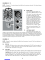
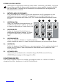
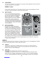
4. PARALLEL LEFT/RIGHT SPEAKER OUTPUTS:
These 1/4" jacks are the outputs for the two
internal amplifiers. You will notice that there
are two pairs of jacks with another jack in
the middle. The two pairs are the two (L/R)
amp outputs. Two cabinets can be connected to
each amplifier, as long as the combined impedance of the cabinets is not less than 4 ohms. (i.e.,
two 8 ohms cabinets in parallel = 4 ohms, four 16 ohms speakers in parallel = 4 ohms, etc.) Do not
use the Bridge Output (5) while using these outputs. The outputs from these jacks are
determined by the System Mode Switch (20).
5. BRIDGE OUTPUT:
The bridge output of the XR 800F allows the power of the left and right amplifiers to be
combined into one mono output in applications where only one speaker will be used. To use
the bridge output, the system mode switch must be in the Left/Right position. Connect an 8
ohm minimum impedance speaker to the center bridge output jack.
231
454
4

CAUTION: When the bridge outputs are being used, no other speakers should be connected
to the adjacent parallel speaker outputs. In addition, the minimum load for the XR 800F in
bridge mode is 8 ohms. Do not allow the total impedance to drop below 8 ohms or serious damage
to the amplifier may occur.
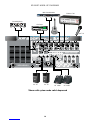
MASTER IN/OUT
The MASTER IN/OUT section describes the functions related to the input and output patch panel
located on the rear of your XR 800F. This section is often overlooked but adds the most versatility to
the XR 800F. When used to its fullest potential, an extraordinary variety of wiring configurations can
be made. These connections allow for devices such as outboard effects, power amps, monitors, and
virtually any other type of line level audio device to be patched in to the XR 800F. Some of these
configurations are displayed in the hookup diagram found at the end of this manual.
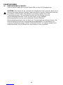
6. POWER AMP INPUTS:
Plugging into these jacks allows the user to go
directly into the Graphic Equalizers (L and R),
then into its respective power amplifier channel.
The jacks for these inputs are switching jacks.
This means that if you plug into the jack you
will defeat any prior signal from the channel,
master and effects sections of the amp. A
benefit of this feature is that you can then use
the internal stereo EQ and power amp with or
without using the channel and effects sections.
Essentially, you can use the XR 800F as a
slave stereo EQ/power amp when needed.
7. LEFT OUTPUT:
This 1/4" jack provides an output from the Left Main mix to supply external amp/speaker
combinations. The level of this signal is determined by the Left Master Fader.
8. RIGHT OUTPUT:
This 1/4" jack provides an output from the Right Main mix to supply external amp/speaker
combinations. The level of this signal is determined by the Right Master Fader.
9. MONITOR OUTPUT:
This 1/4" jack provides an output from the monitor mix to supply external power amp/monitor
combinations. The level of this signal is determined by the Monitor Master Fader.
10. EFX OUTPUT:
This 1/4" jack provides an output of the effects mix. (The same signal that goes to the internal
effects processor.) This signal can be used with external effects units or as an additional (post
fader) monitor output.
11. EFX DEFEAT: This 1/4" (Tip/Sleeve) jack provides a means to defeat the internal effects of
the XR 800F. A standard on/off footswitch, such as the Peavey part number 5100, is
recommended.
67 9
810
11
5

MASTER FUNCTIONS
The MASTER FUNCTIONS section describes those features that are considered master controls.
Essentially, this makes up all of the functions on the right-hand, front panel side of your XR 800F.
The areas of detail include; Effects, EQ/FLS and Monitor/Master Level Controls.
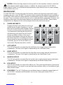
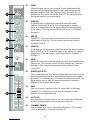
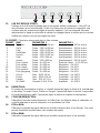
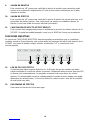
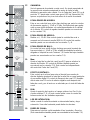
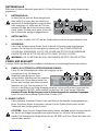
12. EFFECTS PEAK LED:
Illuminates to indicate -6 dB of headroom before the signals being sent to the effects circuit
are clipped. Ideally, you would want this LED to light only occasionally if at all. An occasional
blink indicates that you have the levels at an optimum setting. It is advisable to listen carefully
to the output at the same time in order to determine the final setting. If you hear distortion
then one or more of the input digital effects level controls are set too high.
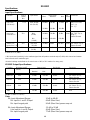
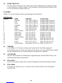
13. PRESET: Selects the effect preset from the list below.
EFX Presets
PRESET NAME TIME/SIZE COLOR/TONE
1 Chamber Time: 150 to 5,000 ms Damping (High Frequency)
2 Plate Time: 100 to 4,000 ms Damping (High Frequency)
3 Room Time: 150 to 5,000 ms Damping (High Frequency)
4 Cathedral Time: 100 to 8,000 ms Damping (High Frequency)
5 Spring Time: 150 to 5,000 ms Damping (High Frequency)
6 Gate Time: 150 to 500 ms Damping (High Frequency)
7 Reverse Time: 150 to 500 ms Damping (High Frequency)
8 Delay + Reverb Time: 0 to 225 ms Reverb Time: 0 to 5,000 ms
9 Bright Delay Time: 0 to 500 ms Feedback: 0 to 99%
10 Warm Delay Time: 0 to 500 ms Feedback: 0 to 99%
11 Dark Delay Time: 0 to 500 ms Feedback: 0 to 99%
12 Ping Pong Delay Time: 0 to 500 ms Feedback: 0 to 99%
13 Chorus Rate: 0.125 to 8 Hz Depth: Best Set Full CW
14 Phaser Rate: 0.250 to 16 Hz Depth: Best Set Full CW
15 Flange Rate: 0.10 to 2.5 Hz Depth: Best Set Full CW
16 Rotary Speaker High Speed: 0.50 to 25 Hz Width: 0 to 100% CW
14. TIME/SIZE:
In Reverb and Delay presets (presets 1-12), this control adjusts the time of the particular
reverb or delay; in Chorus, Phaser, and Flange, it adjusts the rate of each. In Rotary Speaker
setting, this adjusts the speed of the speaker rotation.
15. COLOR/TONE:
Adjusts the high frequency content of the effects signal. (While using a delay, this control
adjusts the feedback or depth.)
16. EFX to MON:
Controls the amount of effects signal sent to the monitor mix. This control allows effects to be
heard from the stage via the monitor.
17. EFX to MAIN: Controls the amount of effects signal sent to the main mix.
12 13 14 15 16 17
6

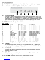
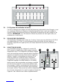
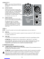
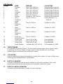
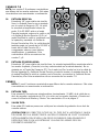
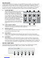
18. FLS (Feedback Locator System):
These LEDs illuminate to indicate the frequency band of highest energy. When feedback
occurs, this system will automatically indicate the graphics slider to use to lessen or eliminate
feedback. (NOTE: These LEDs illuminate with any audio signal, not just during feedback.) If
feedback occurs, pull down the slider under the brightest LED.
19. GRAPHIC EQUALIZERS:
These nine-band equalizers are fixed on one-octave centers. They are designed for 12 dB of
cut and 12 dB boost. They are connected directly to their power amplifier inputs. The signal
sent to each equalizer is determined by the System Mode Switch (20).
20. SYSTEM MODE SWITCH:
This switch is used to configure the XR 800F as either a stereo or dual mono amplifier. It is
recessed to prevent accidental switching during a performance. Use a non-metallic object to
change the switch position (e.g., a toothpick). The XR 800F is shipped from the factory in the
default setting of Left Main to the upper EQ and Right to the lower EQ. When this switch is
depressed it switches the lower EQ to (mono) PA Left + Right. The upper EQ then becomes
the Monitor signal only, creating an entire PA and Monitor mixing system in one small, easy-
to-carry package. And this change is accomplished without a single patch cord!
21. POWER LED:
The power on LED indicator will light when the
unit is powered.
22. MONITOR MASTER FADER: Sets the overall level
of the monitor signal that is sent to the Monitor
Output (9) jack. See page 5.
23. SIGNAL LEVEL METERS: Displays overall level of
either the L and R signals or the Mon and L+R (mix)
signals. The System Mode Switch determines which
mode the meter will operate in. Red Clip LEDs are
located at the top of each meter to indicate clipping.
A clipped signal may damaged your speakers.
To prevent possible speaker damage reduce the
respective fader level.
7
18
19
21 23 20
22 24

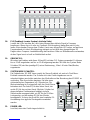
24. MASTER L/R FADERS:
This is the master level control for the L and R signals sent to the Left and Right Output
jacks. When in Main/Monitor mode [see System Mode Switch (20)] the Monitor Fader controls
the monitor signal present at the Left/Mon Power Amp Output (4). The Left and Right Faders
would then control the L/R Mix present at the Right/L+R Power Amp Output (4). The nominal
position for this control is the 0 dB position.
CHANNEL FUNCTIONS
The CHANNEL FUNCTIONS section describes the controls and input connections for each channel
of the XR 800F. Most features are found on all channels, however, there are some differences in
channel’s 7, 8 and 9. Therefore, this section is divided to properly indicate those differences.
CHANNELS 1-6 25. MIC INPUT:
XLR balanced, low impedance channel input optimized for a microphone
or other low-level source. Pin 2 is the positive input. Because of the wide
range of gain adjustment, signal levels as high as +10 dBV (2.45 V RMS)
can be accommodated. When the phantom power is enabled, this
connector has +48 V on Pins 2 (in phase) and 3 with Pin 1 as the ground
reference.
26. LINE INPUT:
1/4" balanced TRS line level input. The tip is the positive (in phase) input,
which can also be used for unbalanced inputs. This signal is connected
through a 20 dB pad to the mic input below it. Within the same channel, the Mic Input and the
Line Input cannot be used simultaneously. Channels 7 and 8 feature stereo versions of the
Line Input. (See features 36 and 37 page 10.)
25
26
8

27. GAIN:
Varies the input gain to each channel. Proper adjustment of the
input gain will maximize the signal to noise ratio giving you the
quietest operation. With your Channel Fader (35) set to the “0”
position, set this control so that the Clip LED (34) barely lights at
the highest peaks in your input signal.
28. HIGH EQ:
A shelving type of active tone control that varies the treble
frequency levels ±15 dB at 12 kHz. It is designed to remove
noise or to add brilliance to the signal, depending on the quality
of the source. (The high control can also be found on Channels 7
through 9.)
29. MID EQ:
Mid ±15 dB. This control sets the amount of cut or boost at the
mid-frequency (850 Hz). The mid control can also be found on
Channels 7 and 8.
30. LOW EQ:
A shelving type of active tone control that varies the bass frequency
levels ±15 dB at 70 Hz. It will add depth to thin signals, or clean up
muddy ones. (The low control can also be found on Channels 7
through 9.)
31. MON:
Adjusts the level of the channel signal (pre-EQ) that is added to the
Monitor mix. (The Monitor control can also be found on Channels 7
through 9.) This control is independent of the Channel Fader
control (35).
32. DIGITAL EFFECTS:
This control varies the level into the digital effects processor bus by
adjusting the signal level from the particular channel to the digital
processor. The channel Gain (27) control also affects this level. The
digital effects send is after the channel fader and is therefore
affected by the channel fader setting.
33. PAN:
Sets the channel’s position in the L/R stereo field. In the stereo
Channels (7, 8 and 9) this control acts as a balance control
between the two separate inputs.
34. CLIP LED:
Indicates when the signal input is too strong and signal clipping is
present. A clipped signal may damage your speakers.
35. CHANNEL FADER:
Sets the signal level sent to the Left and Right bus. (This feature
can also be found on Channels 7 through 9.)
9
27
28
29
30
31
32
33
34
35

CHANNELS 7 - 8
NOTE: Channels 7 - 8 contain features that differ from the previous channels. Only those features
are mentioned below.
36. RIGHT INPUT:
1/4" input for line level signals. The
Right Input is not adjusted by the Gain
(27) control. The signal is then routed
to the internal power amp. If the
XR 800F is in Left/Right mode then
the signal will go to the Right Speaker
Output (4). In Mon/Main mode the
signal is combined with the Left and
placed on the Right/L+R Speaker
Output. The right signal can also be
patched out of the XR 800F via the
Right Output jack (8) to external
components such as effects, power
amps, and recording devices. This
feature is only found on Channels 7
and 8.
37. LEFT/MONO INPUT:
1/4" input for line level signals. The
Left/Mono input supplies signal to both the Left and Right channels (if there is nothing inserted to
the right input jack). It is not adjusted by the Gain Control (27). In Left/Right mode the signal will go
to the Left Speaker Output (4) and Right Speaker Output if nothing is inserted to the right input jack.
In Mon/Main mode the signal is combined with the Right and placed on the Right/L+R Speaker
Output. This feature is only found on Channels 7 and 8.
CHANNEL 9
NOTE: Channel 9 contains features that differ from the previous channels. Only those features are
mentioned below.
38. TAPE IN:
This stereo RCA phono jack accepts a stereo input (nominally -10 dBV) from the output of a
tape deck or CD player and places it on the Left and Right channels as well as the Monitor
and Effects Mix. See feature 31 on page 9.
39. TAPE OUT:
This stereo RCA phono jack provides a signal for the recording inputs of a stereo tape deck.
CAUTION! DO NOT HOOK THE TAPE IN AND TAPE OUT TO THE INPUT AND OUTPUT
OF THE SAME DECK AT THE SAME TIME. DOING SO WILL FORM A LOOP CAUSING
SEVERE FEEDBACK. USE SEPARATE DECKS FOR RECORDING AND PLAYBACK, OR
USE THE INPUTS AND OUTPUTS OF THE SAME DECK AT SEPARATE TIMES.
38
39
40
37
36
10

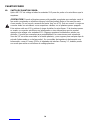
PHANTOM POWER
40. PHANTOM POWER SWITCH:
Applies 48 V DC voltage to all input XLR connectors to power microphones that require it.
CAUTION! When phantom power is switched on, make sure that any channel you are
plugging a mic into is turned down in both the main and monitor mixes. Otherwise, there will
be a loud pop in the PA. This is normal. It is best to plug all mics into their respective
channels with the phantom power switched off. This reduces noise in the PA and reduces the
chances of the mic being damaged. If phantom power is used, do not connect unbalanced
microphones or other devices that cannot handle this voltage to the XLR inputs. (Some
wireless receivers may be damaged; consult their manuals for compatibility.) The line input
1/4" jacks are not connected to the phantom supply, and are safe for all inputs (balanced or
unbalanced). An unbalanced-to-balanced impedance converter, such as the Peavey 5116 or a
Peavey 1:1 Interface Adapter, can also be used to isolate a mic from phantom voltage.
11

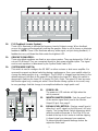
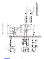
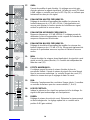
20 dB Pad
CHANNELS 1-6
+48V PHANTOM
LO-Z INPUT
LINE INPUT
Monitor
PAN
Pre Gain
LEVEL EFX LEVEL
CHANNELS 7-8
STEREO LINE INPUT
L/MONO
LO MID HI
Tone Control
LO MID HI
Tone Control PAN/BALANCE
LEVEL
RIGHT
+48 PHANTOM
LO-Z INPUT MIC PREAMP
MIC GAIN
MONTOR
CHANNELS 9 (TAPE)
TAPE/CD
INPUT
LO HI
Tone Control
LEVEL
BALANCE
BALANCE
MONTOR
LO HI
MONTOR
MASTER
MONTOR OUTPUT
RIGHT MAIN OUTPUT
RIGHT POWER AMP INPUT
MODE SELECT
LEFT POWER AMP INPUT
LEFT MAIN OUTPUT
TAPE OUT
EFFECTS TO
MONITOR
PEAK
LED EFFECTS
SELECTOR
TIME COLOR
EFFECTS TO MAIN
EFFECTS DEFEAT
EFFECTS OUT
DIGTAL EFFECTS
LEFT/ L-R
RIGHT MON
POWER AMP
LEFT/ MON
POWER AMP OUT
BRIDGE OUT
RIGHT/L+R
POWER AMP OUT
POWER AMP
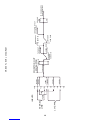
9 BAND EQUALIZER WITH FLS
9 BAND EQUALIZER WITH FLS
63 125 250 500 1K 2K 4K 8K 16K
63 125 250 500 1K 2K 4K 8K 16K
LO MID HI
EFX LEVEL
PAN/BALANCE
210 WATTS PER CHANNEL • 4 OHMS
150 WATTS PER CHANNEL • 8 OHMS
BRIDGE 420 WATTS • 8 OHMS
MON BUS
EFF BUS
LEFT BUS
RIGHT BUS
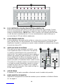
XR800F BLOCK DIAGRAM
12

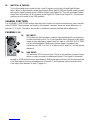
INPUTS
STEREO
LINE TAPE LINE
LO-Z MIC
-60
-50
-40
-30
-20
-20
0dBu
+10
+20
+30 +21 dBu
+16 dBu
+11 dBu
+5 dBu
-48 dBu
-29 dBu
MONITOR OUT
+21 dBu MAX.
2 dBu-0 dBV
-15 dB CHANNEL
FADER
0 dB GAIN
-10 dBV MON
TAPE OUT
-10 dBV MAX
MONITOR OUT
+21 dBV MAX
L/R FADER
10 dB GAIN
LEFT & RIGHT OUT
+21 dBu MAX GRAPHIC
EQ
+12 dB
-12 dB
TO POWER AMPS
+2 dBu NOMINAL
+15 dB
CHANNEL EQ
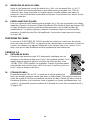
XR800F LEVEL DIAGRAM
13


XR 800F
Specifications:
Input Specifications:
Function Input Z Input Gains Input Levels Bal/ Connector
(ohms) Min** Nominal* Max UnBal.
Min
Low-Z Mic 2.2 k Max (48 dB) -68 dBu -48 dBu -27 dBu Bal. XLR: Pin 1 Gnd,
(150 ohms) Min (10 dB) Pin 2 (+),
Pin 3 (-)
-30 dBu -10 dBu +11 dBu
Line Input 22 k Max -49 dBu -29 dBu -8 dBu Unbal. 1/4" TRS: Tip (+),
Channels 1-6 (29 dB) Ring (-),
Sleeve Ground
Min -11 dBu +10 dBu +31 dBu
(-10 dB)
Stereo Line 22 k Max Gain -20 dBu 0 dBu +21 dBu Unbal. 1/4" Phono Tip (+),
Inputs Chs. 7-8 (20) dB) Sleeve Ground
Tape 20 k Max. Gain -26 dBu -6 dBu +16 dBu Unbal. RCA Jacks
(26 dB)
0 dBVu=0.775 V (RMS)
** Min input level (sensitivity) is the smallest signal that will produce nominal output (2 dBu) with channel and master
level controls set for maximum gain.
* Nominal settings are defined as all controls set a 0 dB (or 50% rotation for rotary pots).
XR 800F Output Specifications:
Function Minimum Load Z Output Level Bal./Unbal. Connector
(ohms) Nominal Max
Main L/R 600 +2 dBu +21 dbu Unbal. 1/4" Phono Tip (+),
Sleeve Ground
Monitor 600 +2 dBu +21 dBu Unbal. 1/4" Phono Tip (+),
Sleeve Ground
Effects 600 +2 dBu +21 dBu Unbal. 1/4" Phono Tip (+),
Sleeve Ground
Tape 10 k -10 dBu +10 dBu Unbal. RCA
+2 dBu = 0 dBV = 1V (RMS)
Gain:
Mic Input Adjustment Range:
Mic Input to L and R Output
Mic Input longest path
Mic Input Adjustment Range:
Line Input to L and R Output
Mic Input longest path
10 dB to 48 dB
68 dB (Max Gain)
96 dB (Max Gain) power amp out
-10 dB to 28 dB
49 dB (Max Gain)
77 dB (Max Gain) power amp out
15

16
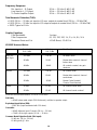
Frequency Response:
Mic Input to L - R Output
Line Input to L - R Output
To Power Amplifier Output
20 Hz — 20 kHz +0 dB/-1 dB
20 Hz — 20 kHz +0 dB/-1 dB
20 Hz — 20 kHz +0 dB/-1 dB
Graphic Equalizer:
Filter Bandwidth
Filter Frequencies
Maximum Boost and Cut
1 octave
63, 125, 250, 500, 1 k, 2 k, 4 k, 8 k, 16 k
+12 dB Boost, -12 dB Cut
Total Harmonic Distortion (THD):
< 0.01% 20 Hz — 20 kHz mic input to L/R mon. output at nominal level (20 Hz — 80 kHz BW)
< 0.01% 20 Hz — 20 kHz line input to L/R output at output at nominal level (20 Hz — 80 kHz BW)
< .005% Typical at 1 kHz
XR 800F Hum and Noise:
Output Residual Noise S/N Ratio Test Conditions
Ref: 0 dBu Ref: 2 dBu
Main Left -100 dBu 100 dB All faders down
and Right -90 dBu 90 dB Master fader nominal, channel
faders down
-84 dBu -84 dB All controls nominal, mic gain
minimum
Monitor -100 dBu 100 dB All controls down
-89 dBu 89 dB Master fader nominal, channel
sends down
-81 dBu -81 dB Master Fader Nominal,
Channel Send Nominal
Effects -87 dBu 87 dB All channel sends down
-81 dBu 81 dB All channel sends nominal
(Hum and noise measurements: 22 Hz to 22 kHz BW)
S/N Ratio:
> 85 dB below rated output (200 W/channel), mic/line to speaker output
Equivalent Input Noise (EIN):
-128.5 dBu (Input terminated with 150 ohms)
Crosstalk:
> 80 dB Adjacent Input Channels (20 Hz — 20 kHz)
> 70 dB Left to right outputs (20 Hz — 20 kHz)
Common Mode Rejection Ratio (Mic Input):
50 dB min. (20 Hz - 20 kHz)
60 dB typical @ 1 kHz

POWER SECTION
(400 SC Module with DDT™)
Power and Load:
210 W RMS per channel into 4 ohms
150 W RMS per channel into 8 ohms
420 W RMS Bridge into 8 ohms
Frequency Response:
20 Hz—20 kHz +0 dB/-1 dB
Total Harmonic Distortion:
<0.02% at rated output @ 1 kHz
DDT™Dynamic Range:
Greater than 26 dB
DDT™Maximum Distortion:
Below 0.5% THD for 6 dB overload
Below 1% THD for 20 dB overload
Hum and Noise:
-100 dB below 210 watts
Damping Factor:
Greater than 100 @ 1 kHz, 4 ohms
Input Impedance:
2 k ohms
Power Requirements:
Dom.: 120 V AC 60 Hz 360 W Nom.
Exp.: 220-230 V AC 50/60 Hz 360 W Nom.
Dimensions (H x W x D):
7.75" x 17.375" x 15.5"
(19.69 cm x 44.13 cm x 3.81 cm)
Weight:
33.6 lbs. (15.24 kg)
17

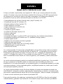
MIXEUR AMPLIFIE R™800F
Nous vous félicitons pour l’achat de cette table amplifiée XR™800F. Ce nouveau mixeur amplifié
constitue une version 9 canaux en un format table de la XR 684. Nous avons regroupé en un même
appareil un nombre impressionnant de fonctionnalités, chacune utilisant les technologies les plus
récentes. Voici certaines d’entre elles:
• Huit entrées micro Jack haute impédance (Canaux 1-8)
• Six entrées ligne Jack (Canaux 1-6)
• trois entrées ligne stéréos (Canaux 7-9)
• Fader canaux et master de 60mm
• LED d’écrêtage sur chaque canal
• Contrôles stéréo pan
• Equalisation 3 bandes (Canaux 1-8)
• Sortie Monitor send (chaque canal)
• Sortie EFX send (chaque canal)
• 16 effets numériques stéréo DSP 32 bit avec 2 paramètres par effet
• Deux EQs graphiques 9 bandes avec FLS®(Système de localisation du Feedback)
• Alimentation phantom 48 V
• Sélecteur de mode Main/Monitor
• 2 VU-mètres master 7 segments
• Amplificateurs de puissance internes 2x210 W @ 4 Ohm
• 420 W @ 8 Ohm en mode bridge
• Protection des haut-parleurs DDT™
Les canaux standards (1-6) possèdent des préamplis faible bruit, une alimentation phantom
générale, des entrées micro haute impédance Jack et des EQ trois bandes. Trois canaux stéréos
(7-9) permettent de connecter des platines cassettes, CD ou des synthétiseurs. Les canaux 7 à 8
sont similaires aux canaux 1 à 6 avec en plus des entrées Jacks stéréos. Le canal 9 possède un
équaliseur 2 bandes, pas de contrôle de gain, et des entrées et sorties stéréos “tape”.
La section master possède 2 EQ graphiques 9 bandes et un unique sélecteur de mode. Sans
réaliser aucun branchement, la XR 800F peut être utilisée comme mixeur et amplificateur pour le
bus Main (mode par défaut). Dans ce mode, les équaliseurs et les amplificateurs affectent le signal
Main aux sorties droite et gauche de la XR800F. En mode Main/Monitor, un équaliseur et un
amplificateur s’occupent du signal Droite+Gauche et l’équaliseur et l’amplificateur restant s’occupent
du signal Monitor (retours).
16 effets numériques issus de notre processeur d’effet Deltafex™sont par ailleurs intégrés (réverbe
et delay). Grâce aux paramètres Size/Time et Color/Tone, l’utilisateur peut aisément adapter les
différents effets à ses besoins. Tous les canaux, canal 9 inclu, possèdent un réglage Effect Send
déterminant la quantité de signal envoyé au processeur d’effet DSP.
Pour tirer tous les avantages de votre XR 800F, lisez attentivement ce manuel et conserver-le en
guise de référence. Les contrôles, les différents type d’application et les branchements sont tous
expliqués en détails dans les différentes sections qui le composent.
FRANÇAIS
18

ALIMENTATION
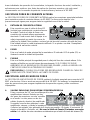
1. CONNECTEUR D’ALIMENTATION:
Prise pour cordon d’alimentation IEC, fournissant l’électricité à la console de mixage/ampli.
Branchez le cordon d’alimentation pour mettre la console sous tension. L’équipement peut
être endommagé si une tension d’alimentation incorrecte est utilisée (voir les spécifications
de tension sur la console).
2. MARCHE/ARRÊT
Interrupteur d’alimentation principal de la table
de mixage. La LED d’alimentation (n°21)
s’allume lorsque la console est sous tension.
3. FUSIBLE:
Ce fusible est connecté à l’alimentation principale. Ne remplacez le fusible que par un
modèle du même type et de même valeur. SI LE FUSIBLE GRILLE CONSTAMMENT,
APPORTEZ L’APPAREIL À UN RÉPARATEUR PEAVEY AGRÉÉ.
ATTENTION: NE REMPLACEZ LE FUSIBLE QUE LORSQUE L’APPAREIL EST
DECONNECTE DE TOUTE ALIMENTATION.
SECTION AMPLIFICATEURS DE PUISSANCE
Cette section présente les différentes connections possibles de la XR 800F à vos enceintes
de sonorisation. Respectez les indications suivantes afin d’assurer le bon fonctionnement de
votre système.
4. SORTIES PARALLÈLES DROITE/GAUCHE:
Ces prises sont les sorties des amplificateurs de puissance. Reliez les enceintes à ces
sorties par un câble HP. Deux paires de sorties et une prise
jack Bridge sont fournies. Les deux paires
sont les sorties des deux amplificateurs
(stéréo). Deux enceintes peuvent être
connectées sur chaque canal, leur charge
combinée devant toujours être supérieure à
4 Ohm (par exemple, 2 enceintes de 8 Ohm connectées en parallèle = 4 Ohm, enceintes de
16 Ohm connectées en parallèle = 4 ohms, etc). N’utilisez pas la sortie Bridge (5)
simultanément! Les signaux à ces sorties sont déterminés par le sélecteur de mode (20)
5. SORTIE BRIDGE:
La sortie Bridge du XR 800F permet de combiner les amplificateurs droit et gauche pour une
sortie mono de plus forte puissance. Lors de l’utilisation de la sortie Bridge, l’amplificateur
doit être en mode Left/Right (sélecteur n°24). Connectez une charge d’impédance minimum
de 8 Ohm à cette sortie.
ATTENTION : Lors de l’utilisation de la sortie Bridge, les sorties parallèles adjacentes ne
doivent pas être utilisées. La charge totale acceptable du XR 800F en mode Bridge est de 8
Ohm. Si l’impédance de charge atteint une valeur inférieure, l’amplificateur est susceptible de
subir de sérieux dommages.
231
454
19

ENTREES/SORTIES MASTER
Cette section se rapporte aux entrées et sorties situées à l’arrière de la XR 800F. C’est là que
devront être connectés les divers amplis de puissance, retours amplifiés et modules d’effets
que vous utiliserez. Certaines de ces connexions sont expliquées dans le diagramme de
branchements de ce manuel.
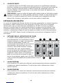
6. ENTRÉES AMPLI DE PUISSANCE:
En se connectant à ces entrées, vous accédez directement aux EQ graphiques et à leur
amplificateur de puissance respectif. Tout signal situé en amont des équaliseurs sera
déconnecté. Vous pouvez ainsi utiliser la XR 800F comme amplificateur/équaliseurs stéréo
esclave.
7. SORTIE GAUCHE:
Sortie Jack fournissant le mix gauche pour un
amplificateur de puissance externe. Le niveau
du signal est déterminé par le fader Master Left.
8. SORTIE DROITE:
Sortie Jack fournissant le mix droit pour un
amplificateur de puissance externe. Le niveau
du signal est déterminé par le fader Master
Right.
9. SORTIE MONITOR:
Sortie Jack destinée à alimenter un ampli de puissance
externe assigné aux retours. Le niveau du signal est déterminé par le fader Monitor Master.
10. SORTIE EFX:
Sortie Jack fournissant le mix Effet pour un processeur externe. C’est ce même signal qui est
envoyé aux DSP interne. Cette sortie peut aussi être utilisée pour un systéme de retour
(sortie post-fader).
11. ACTIVATION EFX:
Cette entrée Jack est destinée à un footswitch de type On/Off (Accessoire Peavey
n°00051000) pour engager et désengager les effets.
FONCTIONS MASTER
Cette section s’attache à décrire les contrôles principalement situés sur la droite de la table de
mixage tels les effets, équaliseurs et contrôles Monitor/Master.
67 9
810
11
20
Seite laden ...
Seite laden ...
Seite laden ...
Seite laden ...
Seite laden ...
Seite laden ...
Seite laden ...
Seite laden ...
Seite laden ...
Seite laden ...
Seite laden ...
Seite laden ...
Seite laden ...
Seite laden ...
Seite laden ...
Seite laden ...
Seite laden ...
Seite laden ...
Seite laden ...
Seite laden ...
Seite laden ...
Seite laden ...
Seite laden ...
Seite laden ...
Seite laden ...
Seite laden ...
Seite laden ...
Seite laden ...
-
 1
1
-
 2
2
-
 3
3
-
 4
4
-
 5
5
-
 6
6
-
 7
7
-
 8
8
-
 9
9
-
 10
10
-
 11
11
-
 12
12
-
 13
13
-
 14
14
-
 15
15
-
 16
16
-
 17
17
-
 18
18
-
 19
19
-
 20
20
-
 21
21
-
 22
22
-
 23
23
-
 24
24
-
 25
25
-
 26
26
-
 27
27
-
 28
28
-
 29
29
-
 30
30
-
 31
31
-
 32
32
-
 33
33
-
 34
34
-
 35
35
-
 36
36
-
 37
37
-
 38
38
-
 39
39
-
 40
40
-
 41
41
-
 42
42
-
 43
43
-
 44
44
-
 45
45
-
 46
46
-
 47
47
-
 48
48


Peavey XR 800F Benutzerhandbuch
- Kategorie
- Musikinstrumentenverstärker
- Typ
- Benutzerhandbuch
- Dieses Handbuch ist auch geeignet für
in anderen Sprachen
- English: Peavey XR 800F User manual
- français: Peavey XR 800F Manuel utilisateur
- español: Peavey XR 800F Manual de usuario