Pepperl+Fuchs NDP5-30GM-5M Bedienungsanleitung
- Typ
- Bedienungsanleitung

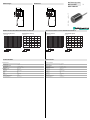
Abmessungen
Elektrischer Anschluss/Kurven/
Zusätzliche Informationen
Electrical Connection / Curves / Additional Information
Dimensions
Technische Daten
Technical data
NDP5-30GM-5M
36
3
40
43
5
M30 x 1.5
5000
36
3
40
43
5
M30 x 1.5
5000
Part. No.:
Date:
200661
11/30/2010 DIN A3 -> DIN
45-3430
Doc. No.:
Allgemeine Daten
Einbau nicht bündig
Übertragungsabstand 0 ... 5 mm
Umgebungsbedingungen
Umgebungstemperatur 0 ... 50 °C (32 ... 122 °F)
Lagertemperatur -25 ... 85 °C (-13 ... 185 °F)
Mechanische Daten
Anschlussart Kabel PVC , 5 m
Aderquerschnitt 0,75 mm2
Gehäusematerial Messing, vernickelt
Stirnfläche PBT
Schutzart IP67
Montage Schraubmontage
Freizone A 3 mm
Abstand zu Metallwänden B Ø 50 mm
Sicherheitszone W x H 60 mm x 15 mm
General specifications
Installation not embeddable
Transfer distance 0 ... 5 mm
Ambient conditions
Ambient temperature 0 ... 50 °C (32 ... 122 °F)
Storage temperature -25 ... 85 °C (-13 ... 185 °F)
Mechanical specifications
Connection type cable PVC , 5 m
Core cross-section 0.75 mm2
Housing material brass, nickel-plated
Sensing face PBT
Protection degree IP67
Installation screw mounting
Free zone A 3 mm
Spacing to metal walls B Ø 50 mm
Security zone W x H 60 mm x 15 mm
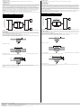
WIS Übertrager primär
WIS transmitter
-5 -4 -3 -2 -1 0 1 2 3 4 5
5
4
3
2
1
0
x
y
Transfer distance
Misalignment Y [mm]
Distance X [mm]
Transferable power
Misalignment
Y = 0 mm
Distance X [mm]
Power [W]
3
2.5
2
1.5
1
0.5
0
0 1 2 3 4 5 6
x
y
-5 -4 -3 -2 -1 0 1 2 3 4 5
5
4
3
2
1
0
x
y
Versatz Y [mm]
Übertragungsabstand
Abstand X [mm]
Versatz Y = 0 mm
Übertragbare Leistung
Abstand X [mm]
Leistung [W]
3
2.5
2
1.5
1
0.5
0
0 1 2 3 4 5 6
x
y

Adressen / Addresses / Adresses / Direcciónes / Indirizzi
Contact Pepperl+Fuchs GmbH · 68301 Mannheim · Germany · Tel. +49 621 776-4411 · Fax +49 621 776-27-4411 · E-mail: fa-info@de.pepperl-fuchs.com
Worldwide Headquarters: Pepperl+Fuchs GmbH · Mannheim · Germany · E-mail: [email protected]l-fuchs.com
USA Headquarters: Pepperl+Fuchs Inc. · Twinsburg · USA · E-mail: fa-in[email protected].com
Asia Pacific Headquarters: Pepperl+Fuchs Pte Ltd · Singapore · E-mail: [email protected]perl-fuchs.com · Company Registration No. 199003130E
For more contact-adresses refer to the catalogue or internet: http://www.pepperl-fuchs.com
Funktionsbeschreibung
Ein induktives Übertragungssystem WIS (wireless inductive system) besteht immer aus den 4 Komponenten:
- WIS-Modul, primär
- WIS-Übertrager, primär
- WIS-Übertrager, sekundär
- WIS-Modul, sekundär.
Das WIS-Modul, primär ist im stationären Anlagenteil installiert und mit einer nachgeschalteten Steuerung (z. B. SPS) verbunden. An das
WIS-Modul, primär ist der WIS-Übertrager, primär angeschlossen. Der WIS-Übertrager, sekundär und das damit verbundene WIS-Modul,
sekundär sind auf dem beweglichen Anlagenteil installiert. Das WIS-Modul, sekundär verfügt über Anschlussmöglichkeiten für mehrere
Sensoren. Stehen sich die beiden Übertrager innerhalb der Systemreichweite gegenüber, so wird elektrische Leistung von der
Primärseite zur Sekundärseite übertragen. Die an das WIS-Modul, sekundär angeschlossenen Sensoren werden nun mit elektrischer
Energie versorgt und nehmen ihren Betrieb auf. Die Sensor-Ausgangssignale werden in der Gegenrichtung von der Sekundärseite an
die Primärseite übertragen und stehen separat an den Ausgangsklemmen des WIS-Moduls, primär zur Weiterverarbeitung durch die
Anlagensteuerung zur Verfügung. Der Status der Sensorsignale wird außerdem über LEDs, welche den Sensorkanälen zugeordnet sind,
angezeigt.
Ein separates Ausgangssignal Tx am WIS-Modul, primär zeigt den Kommunikationszustand an. Ein High-Signal signalisiert
Kommunikation zwischen den WIS-Übertragern. Dies wird auch durch eine leuchtende LED Tx angezeigt.
Über den Eingang EN kann am WIS-Modul, primär die Leistungsübertragung und Kommunikation im System aktiviert oder deaktiviert
werden.
Funktionsschaltbild
Die Summe der Ruheströme aller an das WIS-Modul, sekundär angeschlossenen Sensoren darf nicht größer sein, als der maximal
übertragbare Strom. Dieser errechnet sich aus der durch die Übertrager gegebenen übertragbaren Leistung / 12 V.
Einbaubedingungen
Durch die Übertragung elektrischer Energie zur Sensorversorgung von der Primärseite des Übertragungssystems zur Sekundärseite
erwärmt sich im Betrieb der WIS-Übertrager, primär um ca. 40 K über die Umgebungstemperatur. Der Einbau des WIS-Übertragers in
Anlagenteile aus Metall kann das Abführen der Wärme verbessern.
Bei der Installation mehrerer Systeme muss eine getrennte Kabelführung vorgesehen werden.
Beim Einbau der WIS-Übertrager ist auf Mindestabstände zu Metallteilen zu achten. Durch das induktive Wirkprinzip können durch
Induktion von Wirbelströmen umliegende Metallteile aufgeheizt werden.
Mindestfreizone der beiden WIS-Übertrager bei Einbau in Metall
Zur Vermeidung von Änderungen der Übertragercharakteristik ist der angegebene Abstand zu metallischen Wänden, welche die
Mindestfreizone überragen, an beiden WIS-Übertragern einzuhalten.
Im Bereich der Sicherheitszone darf während des Betriebs nicht mit metallischen Gegenständen hantiert werden.
Wo dies nicht vermieden werden kann, muss die Übertragung mittels entsprechender Ansteuerung des Enable-Eingangs EN deaktiviert
werden.
Die Einbaumaße entnehmen Sie bitte den technischen Daten.
Eingangssignal an EN Funktion
+ UB (24 V DC) Übertragung aktiviert
GND oder offen Übertragung deaktiviert
. . . . . .
. . . . . .
WIS-Modul, primär
WIS-Über-
trager,
primär
WIS-Über-
trager,
sekundär
WIS-Modul, sekundär
Sensoren
Energie
Sensor-
signale
Sensor-Signalausgänge,
Statusausgang, Steuereingang
A
B
Sicherheits-
zone
W
H
Functional description
A WIS (wireless inductive system) inductive transfer system always consists of the following four components:
- WIS primary module
- WIS primary transmitter
- WIS secondary transmitter
- WIS secondary module
The WIS primary module is installed in the stationary component and is connected to a downstream control (i.e., PLC). The WIS primary
transmitter connected to the WIS primary module. The WIS secondary transmitter and the WIS secondary module that is connected to it are
installed in the moveable part of the component. The WIS secondary module disposes of connection capabilities for several sensors. If the
two transmitters are located in front of each other within the system range, then electric power is transferred from the primary side to the
secondary side. The sensors attached to the WIS secondary module are now supplied with electric energy and begin to operate. The sensor
output signals are transmitted in the opposite direction from the secondary side to the primary side and are separately available on the WIS
promary module output terminals for further processing by the equipment control. The sensor signal status is also displayed by LEDs that
correspond to the sensor channels.
A separate output signal Tx on the WIS primary module indicates the communication status. A high signal indicates communication between
the WIS transmitters. This is also indicated by a glowing LED Tx.
Power transfer and communication in the system can be activated and deactivated on the WIS primary module with the EN input .
Function schematic
The sum of the currents of all sensors attached to the WIS secondary module must not be greater than the maximum transferable current.
This is calculated by dividing the transferable power by the 12 V provided by the transmitters.
Installation requirements
During operation, the WIS transmitter heats up due to the transfer of electrical energy for the sensor supply from the primary side of the transfer
system to the secondary side, primarily by about 40 K above the ambient temperature. By installing the WIS transmitter in metal mounting
components heat dissipation can be improved.
If a number of systems are to be installed the cable routing must be isolated.
Care must be taken in terms of the minimum separation from metal parts when installing the WIS transmitter. Because of the inductive
operating principal employed surrounding metal parts can heat up due to the induction of eddy currents.
Minimum ‘free zone’ requirements of the WIS transmitters when installed in metal
In order to avoid changes in the transfer characteristics, care must be taken to ensure that the specified separation from metal walls (which
exceeds the minimum free zone) is always maintained on both WIS transmitters.
Metal objects must not be inserted or handled in the area of the safety zone during operation.
In the event that this cannot be avoided, the transfer must be deactivated with the enable input, EN, on the front of the primary module.
Please refer to the technical data for installation dimensions.
Input signal on EN Function
+ UB (24 V DC) Transfer activated
GND or open. Transfer deactivated
. . . . . .
. . . . . .
WIS primary
WIS
transmitter,
primary
WIS
transmitter,
secondary
WIS secondary module
Sensors
Energy
Sensor
signals
Sensor signal output,
status output, control input
A
B
Safety
zone
W
H
-
 1
1
-
 2
2

