Pepperl+Fuchs NDP-KE2-8E2 Bedienungsanleitung
- Typ
- Bedienungsanleitung

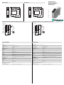
Abmessungen
Elektrischer Anschluss/Kurven/
Zusätzliche Informationen
Electrical Connection / Curves / Additional Information
Dimensions
Technische Daten
Technical data
NDP-KE2-8E2
22.5 857
99
1234
5678
Tx EN GND+24
Lbn Lbn Lbu Lbu
22.5 857
99
1234
5678
Tx EN GND+24
Lbn Lbn Lbu Lbu
-U
B
+U
B
I
1
Lbn
Lbu
2
3
4
5
6
7
8
Tx
EN
GND +24
BN
BU
Anschluss:
Ausgang 1
Ausgang 2
Ausgang 3
Ausgang 4
Ausgang 5
Ausgang 6
Ausgang 7
Ausgang 8
Ausgang
Übertra-
gungsstatus
Aktivierungs-
eingang
-U
B
+U
B
I
1
Lbn
Lbu
2
3
4
5
6
7
8
Tx
EN
GND +24
BN
BU
Connection:
Output 1
Output 2
Output 3
Output 4
Output 5
Output 6
Output 7
Output 8
Transfer
status
output
Enable
input
Part. No.:
Date:
200660
11/30/2010 DIN A3 -> DIN
45-3429
Doc. No.:
Kenndaten
Betriebsspannung UB24 V DC ± 10 %
Anzahl Signalkanäle 8
Übertragungsrichtung der Signale von der Sekundärseite zur Primärseite
Verpolschutz verpolgeschützt
Stromaufnahme max. 1000 mA
Anzeigen/Bedienelemente
Schaltzustand 8 x LED, gelb
Übertragungsanzeige Tx LED, grün
Eingang
Anzahl 1
Eingangstyp Aktivierungseingang
Signalpegel: 15 V = aktiv, 3 V inaktiv
Eingangsstrom 1 mA
Innenwiderstand 15 k
Ausgang
Ausgangstyp 1 Statusausgang (high bei einwandfreier Übertragung) und 8 Schaltausgänge pnp, Schließer (plusschaltend) ,
überlast- und kurzschlussfest
Laststrom max. 50 mA
Ansprechzeit 200 ms ( statischer Betrieb , die Übertragerköpfe stehen sich gegenüber )
Umgebungsbedingungen
Umgebungstemperatur 0 ... 50 °C (32 ... 122 °F)
Lagertemperatur -25 ... 85 °C (-13 ... 185 °F)
Mechanische Daten
Schutzart IP20
Material
Gehäuse PA 66-FR
Montage Hutschienenmontage
Masse 106 g
Normen- und Richtlinienkonformität
Richtlinienkonformität
EMV-Richtlinie 89/336/EWG EN 61000-6-2:2001, EN 61000-6-4:2001, EN 50295:1999
Nominal ratings
Operating voltage UB24 V DC ± 10 %
Number of signal channels 8
Signal transfer direction from secondary side to primary side
Reverse polarity protected reverse polarity protected
Current consumption max. 1000 mA
Indicators/operating means
Switching state 8 x LED, yellow
Transfer indicator Tx LED, green
Input
Number 1
Input type Activation input
signal level: 15 V = active, 3 V inactive
Input current 1 mA
Internal resistor 15 k
Output
Output type 1 Status output (high with proper transfer) and 8 Switch outputs PNP, NO. (switched high) , overload and short-cir-
cuit resistant
Load current max. 50 mA
Response time 200 ms ( static operation , the transmission heads stand opposite to each other )
Ambient conditions
Ambient temperature 0 ... 50 °C (32 ... 122 °F)
Storage temperature -25 ... 85 °C (-13 ... 185 °F)
Mechanical specifications
Protection degree IP20
Material
Housing PA 66-FR
Installation DIN rail mounting
Mass 106 g
Compliance with standards and directives
Directive conformity
EMC Directive 89/336/EEC EN 61000-6-2:2001, EN 61000-6-4:2001, EN 50295:1999
WIS Modul primär
WIS module primary

Adressen / Addresses / Adresses / Direcciónes / Indirizzi
Contact Pepperl+Fuchs GmbH · 68301 Mannheim · Germany · Tel. +49 621 776-4411 · Fax +49 621 776-27-4411 · E-mail: fa-info@de.pepperl-fuchs.com
Worldwide Headquarters: Pepperl+Fuchs GmbH · Mannheim · Germany · E-mail: [email protected]l-fuchs.com
USA Headquarters: Pepperl+Fuchs Inc. · Twinsburg · USA · E-mail: fa-in[email protected].com
Asia Pacific Headquarters: Pepperl+Fuchs Pte Ltd · Singapore · E-mail: [email protected]perl-fuchs.com · Company Registration No. 199003130E
For more contact-adresses refer to the catalogue or internet: http://www.pepperl-fuchs.com
Funktionsbeschreibung
Ein induktives Übertragungssystem WIS (wireless inductive system) besteht immer aus den 4 Komponenten:
- WIS-Modul, primär
- WIS-Übertrager, primär
- WIS-Übertrager, sekundär
- WIS-Modul, sekundär.
Das WIS-Modul, primär ist im stationären Anlagenteil installiert und mit einer nachgeschalteten Steuerung (z. B. SPS) verbunden. An das
WIS-Modul, primär ist der WIS-Übertrager, primär angeschlossen. Der WIS-Übertrager, sekundär und das damit verbundene WIS-Modul,
sekundär sind auf dem beweglichen Anlagenteil installiert. Das WIS-Modul, sekundär verfügt über Anschlussmöglichkeiten für mehrere
Sensoren. Stehen sich die beiden Übertrager innerhalb der Systemreichweite gegenüber, so wird elektrische Leistung von der
Primärseite zur Sekundärseite übertragen. Die an das WIS-Modul, sekundär angeschlossenen Sensoren werden nun mit elektrischer
Energie versorgt und nehmen ihren Betrieb auf. Die Sensor-Ausgangssignale werden in der Gegenrichtung von der Sekundärseite an
die Primärseite übertragen und stehen separat an den Ausgangsklemmen des WIS-Moduls, primär zur Weiterverarbeitung durch die
Anlagensteuerung zur Verfügung. Der Status der Sensorsignale wird außerdem über LEDs, welche den Sensorkanälen zugeordnet sind,
angezeigt.
Ein separates Ausgangssignal Tx am WIS-Modul, primär zeigt den Kommunikationszustand an. Ein High-Signal signalisiert
Kommunikation zwischen den WIS-Übertragern. Dies wird auch durch eine leuchtende LED Tx angezeigt.
Über den Eingang EN kann am WIS-Modul, primär die Leistungsübertragung und Kommunikation im System aktiviert oder deaktiviert
werden.
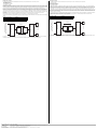
Funktionsschaltbild
Die Summe der Ruheströme aller an das WIS-Modul, sekundär angeschlossenen Sensoren darf nicht größer sein, als der maximal
übertragbare Strom. Dieser errechnet sich aus der durch die Übertrager gegebenen übertragbaren Leistung / 12 V.
Eingangssignal an EN Funktion
+ UB (24 V DC) Übertragung aktiviert
GND oder offen Übertragung deaktiviert
. . . . . .
. . . . . .
WIS-Modul, primär
WIS-Über-
trager,
primär
WIS-Über-
trager,
sekundär
WIS-Modul, sekundär
Sensoren
Energie
Sensor-
signale
Sensor-Signalausgänge,
Statusausgang, Steuereingang
Functional description
A WIS (wireless inductive system) inductive transfer system always consists of the following four components:
- WIS primary module
- WIS primary transmitter
- WIS secondary transmitter
- WIS secondary module
The WIS primary module is installed in the stationary component and is connected to a downstream control (i.e., PLC). The WIS primary
transmitter connected to the WIS primary module. The WIS secondary transmitter and the WIS secondary module that is connected to it are
installed in the moveable part of the component. The WIS secondary module disposes of connection capabilities for several sensors. If the
two transmitters are located in front of each other within the system range, then electric power is transferred from the primary side to the
secondary side. The sensors attached to the WIS secondary module are now supplied with electric energy and begin to operate. The sensor
output signals are transmitted in the opposite direction from the secondary side to the primary side and are separately available on the WIS
promary module output terminals for further processing by the equipment control. The sensor signal status is also displayed by LEDs that
correspond to the sensor channels.
A separate output signal Tx on the WIS primary module indicates the communication status. A high signal indicates communication between
the WIS transmitters. This is also indicated by a glowing LED Tx.
Power transfer and communication in the system can be activated and deactivated on the WIS primary module with the EN input .
Function schematic
The sum of the currents of all sensors attached to the WIS secondary module must not be greater than the maximum transferable current.
This is calculated by dividing the transferable power by the 12 V provided by the transmitters.
Input signal on EN Function
+ UB (24 V DC) Transfer activated
GND or open. Transfer deactivated
. . . . . .
. . . . . .
WIS primary
WIS
transmitter,
primary
WIS
transmitter,
secondary
WIS secondary module
Sensors
Energy
Sensor
signals
Sensor signal output,
status output, control input
-
 1
1
-
 2
2


Pepperl+Fuchs NDP-KE2-8E2 Bedienungsanleitung
- Typ
- Bedienungsanleitung
in anderen Sprachen
Verwandte Artikel
-
Pepperl+Fuchs NDP5-30GM-5M Bedienungsanleitung
-
-
-
-
-
-
-
-