MSI MS-7A31 Bedienungsanleitung
- Kategorie
- Motherboards
- Typ
- Bedienungsanleitung
Dieses Handbuch ist auch geeignet für

I
Quick Start
Quick Start
Thank you for purchasing the MSI
®
X370 XPOWER GAMING
TITANIUM motherboard. This Quick Start section provides
demonstration diagrams about how to install your computer. Some
of the installations also provide video demonstrations. Please link
to the URL to watch it with the web browser on your phone or tablet.
You may have even link to the URL by scanning the QR code.
Kurzanleitung
Danke, dass Sie das MSI
®
X370 XPOWER GAMING TITANIUM
Motherboard gewählt haben. Dieser Abschnitt der Kurzanleitung
bietet eine Demo zur Installation Ihres Computers. Manche
Installationen bieten auch die Videodemonstrationen. Klicken Sie
auf die URL, um diese Videoanleitung mit Ihrem Browser auf Ihrem
Handy oder Table anzusehen. Oder scannen Sie auch den QR Code
mit Ihrem Handy, um die URL zu öffnen.
Présentation rapide
Merci d’avoir choisi la carte mère MSI
®
X370 XPOWER GAMING
TITANIUM. Ce manuel fournit une rapide présentation avec des
illustrations explicatives qui vous aideront à assembler votre
ordinateur. Des tutoriels vidéo sont disponibles pour certaines
étapes. Cliquez sur le lien fourni pour regarder la vidéo sur votre
téléphone ou votre tablette. Vous pouvez également accéder au lien
en scannant le QR code qui lui est associé.
Быстрый старт
Благодарим вас за покупку материнской платы MSI
®
X370
XPOWER GAMING TITANIUM. В этом разделе представлена
информация, которая поможет вам при сборке комьютера.
Для некоторых этапов сборки имеются видеоинструкции.
Для просмотра видео, необходимо открыть
соответствующую ссылку в веб-браузере на вашем телефоне
или планшете. Вы также можете выполнить переход по
ссылке, путем сканирования QR-кода.

II
Quick Start
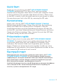
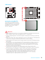
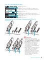
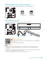
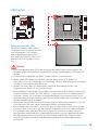
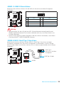
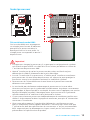
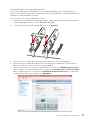
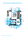
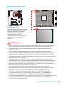
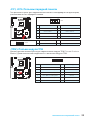
Installing a Processor/ Installation des Prozessors/ Installer un
processeur/ Установка процессора
1
2
3
6
4
5
7
8
9
https://youtu.be/Xv89nhFk1vc

III
Quick Start
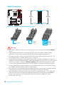
1
1
2
2
3
3
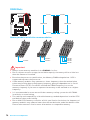
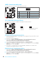
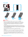
DIMMB2 DIMMB2
DIMMB1
DIMMA2 DIMMA2 DIMMA2
DIMMA1
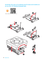
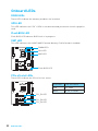
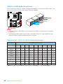
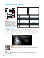
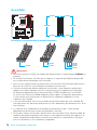
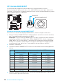
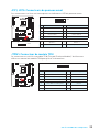
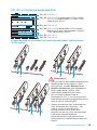
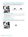
Installing DDR4 memory/ Installation des DDR4-Speichers/
Installer une mémoire DDR4/ Установка памяти DDR4
http://youtu.be/T03aDrJPyQs

IV
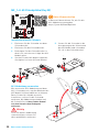
Quick Start
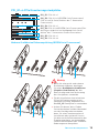
1
2 10
9
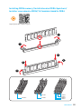
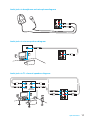
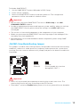
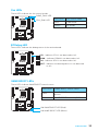
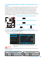
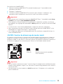
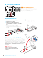
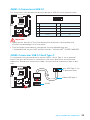
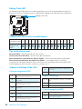
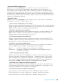
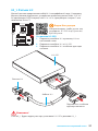
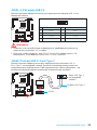
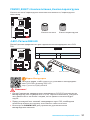
JFP1
1 HDD LED + 2 Power LED +
3 HDD LED - 4 Power LED -
5 Reset Switch 6 Power Switch
7 Reset Switch 8 Power Switch
9 Reserved 10 No Pin
RESET SW
POWER SW
POWER LED+
POWER LED-
HDD LED
HDD LED
RESET SW
JFP1
HDD LED
HDD LED -
HDD LED +
POWER LED -
POWER LED +
POWER LED
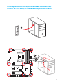
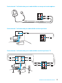
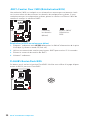
Connecting the Front Panel Header/ Anschließen der
Frontpanel-Stiftleiste/ Connecter un connecteur du panneau
avant/ Подключение разъемов передней панели
http://youtu.be/DPELIdVNZUI

V
Quick Start
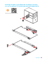
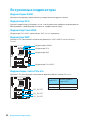
Installing the Motherboard/ Installation des Motherboards/
Installer la carte mère/ Установка материнской платы
1
2

VI
Quick Start
1
2
3
4
5
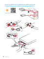
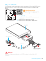
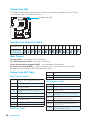
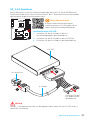
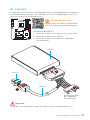
Installing SATA Drives/ Installation der SATA-Laufwerke/
Installer le disque dur SATA/ Установка дисков SATA
http://youtu.be/RZsMpqxythc

VII
Quick Start
1
2
3
4
5
6
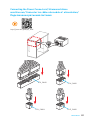
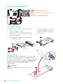
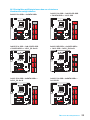
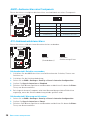
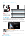
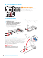
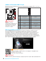
Installing a Graphics Card/ Einbau der Grafikkarte/ Installer
une carte graphique/ Установка дискретной видеокарты
http://youtu.be/mG0GZpr9w_A

VIII
Quick Start
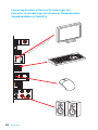
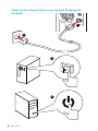
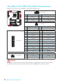
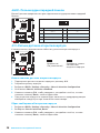
Connecting Peripheral Devices/ Peripheriegeräte/
Connecter un périphérique anschliessen/ Подключение
периферийных устройств
(7th Gen A-series/ Athlon™ CPU)

IX
Quick Start
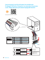
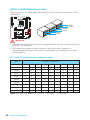
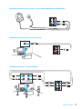
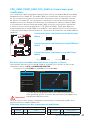
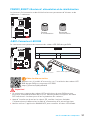
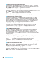
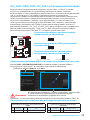
Connecting the Power Connectors/ Stromanschlüsse
anschliessen/ Connecter les câbles du module d’alimentation/
Подключение разъемов питания
http://youtu.be/gkDYyR_83I4
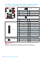
ATX_PWR1
CPU_PWR1
PCIE_PWR1
CPU_PWR2

X
Quick Start
1
4
2
3
Power On/ Einschalten/ Mettre sous-tension/ Включение
питания

1
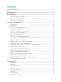
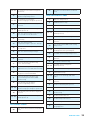
Contents
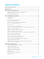
Contents
Safety Information ................................................................................................. 3
Specifications ......................................................................................................... 4
Rear I/O Panel ........................................................................................................ 9
LAN Port LED Status Table..................................................................................... 9
Audio Ports Configuration ...................................................................................... 9
Realtek HD Audio Manager .................................................................................. 10
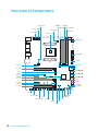
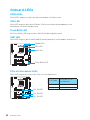
Overview of Components .................................................................................... 12
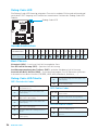
CPU Socket ........................................................................................................... 13
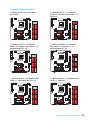
DIMM Slots ............................................................................................................ 14
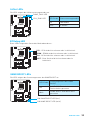
PCI_E1~6: PCIe Expansion Slots .......................................................................... 15
OC1: GAME BOOST Knob ..................................................................................... 18
JSLOW1: Slow Mode Booting Jumper .................................................................. 19
M2_1~2: M.2 Slots (Key M) ................................................................................... 20
U2_1: U.2 Connector ............................................................................................. 21
SATA1~6: SATA 6Gb/s Connectors ....................................................................... 22
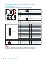
CPU_PWR1~2, ATX_PWR1, PCIE_PWR1: Power Connectors .............................. 24
JUSB1~2: USB 2.0 Connectors ............................................................................. 25
JUSB3: USB 3.1 Gen2 Type-C Connector ............................................................. 25
JUSB4~5: USB 3.1 Gen1 Connectors ................................................................... 26
CPU_FAN1, PUMP_FAN1, SYS_FAN1~4: Fan Connectors ................................... 27
JAUD1: Front Audio Connector ............................................................................ 28
JCI1: Chassis Intrusion Connector ....................................................................... 28
JFP1, JFP2: Front Panel Connectors ................................................................... 29
JTPM1: TPM Module Connector ........................................................................... 29
JBAT1: Clear CMOS (Reset BIOS) Jumper ........................................................... 30
FLASHB1: Flash BIOS Button ............................................................................... 30
POWER1, RESET1: Power Button, Reset Button ................................................. 31
JLED1: RGB LED connector ................................................................................. 31
Onboard LEDs ...................................................................................................... 32
DIMM LEDs ........................................................................................................... 32
GPU LED ............................................................................................................... 32
Flash BIOS LED .................................................................................................... 32
XMP LED ............................................................................................................... 32
PCIe x16 slot LEDs................................................................................................ 32
Fan LEDs ............................................................................................................... 33
EZ Debug LED ....................................................................................................... 33
GAME BOOST LEDs .............................................................................................. 33

2
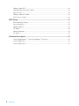
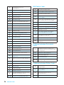
Contents
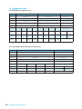
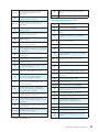
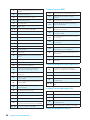
Debug Code LED ................................................................................................... 34
Hexadecimal Character Table .............................................................................. 34
Boot Phases .......................................................................................................... 34
Debug Code LED Table ......................................................................................... 34
ACPI States Codes ................................................................................................ 36
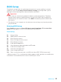
BIOS Setup ........................................................................................................... 37
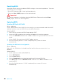
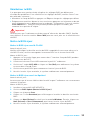
Entering BIOS Setup ............................................................................................. 37
Resetting BIOS ...................................................................................................... 38
Updating BIOS ....................................................................................................... 38
EZ Mode ................................................................................................................ 40
Advanced Mode .................................................................................................... 42
OC Menu................................................................................................................ 43
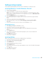
Software Description ........................................................................................... 47
Installing Windows
®
7 64-bit/ Windows
®
10 64-bit ............................................... 47
Installing Drivers .................................................................................................. 47
Installing Utilities ................................................................................................. 47

3
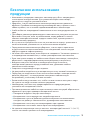
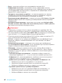
Safety Information
Safety Information
y The components included in this package are prone to damage from electrostatic
discharge (ESD). Please adhere to the following instructions to ensure successful
computer assembly.
y Ensure that all components are securely connected. Loose connections may cause
the computer to not recognize a component or fail to start.
y Hold the motherboard by the edges to avoid touching sensitive components.
y It is recommended to wear an electrostatic discharge (ESD) wrist strap when
handling the motherboard to prevent electrostatic damage. If an ESD wrist strap
is not available, discharge yourself of static electricity by touching another metal
object before handling the motherboard.
y Store the motherboard in an electrostatic shielding container or on an anti-static
pad whenever the motherboard is not installed.
y Before turning on the computer, ensure that there are no loose screws or metal
components on the motherboard or anywhere within the computer case.
y Do not boot the computer before installation is completed. This could cause
permanent damage to the components as well as injury to the user.
y If you need help during any installation step, please consult a certified computer
technician.
y Always turn off the power supply and unplug the power cord from the power outlet
before installing or removing any computer component.
y Keep this user guide for future reference.
y Keep this motherboard away from humidity.
y Make sure that your electrical outlet provides the same voltage as is indicated on
the PSU, before connecting the PSU to the electrical outlet.
y Place the power cord such a way that people can not step on it. Do not place
anything over the power cord.
y All cautions and warnings on the motherboard should be noted.
y If any of the following situations arises, get the motherboard checked by service
personnel:
Liquid has penetrated into the computer.
The motherboard has been exposed to moisture.
The motherboard does not work well or you can not get it work according to user
guide.
The motherboard has been dropped and damaged.
The motherboard has obvious sign of breakage.
y Do not leave this motherboard in an environment above 60°C (140°F), it may damage
the motherboard.

4
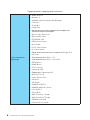
Specifications
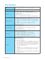
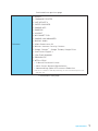
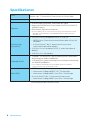
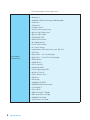
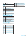
Specifications
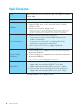
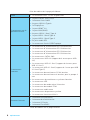
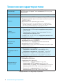
CPU
Supports AMD
®
RYZEN series processors and 7th Gen
A-series/ Athlon™ processors for Socket AM4
Chipset AMD
®
X370 Chipset
Memory
y 4x DDR4 memory slots, support up to 64GB
y Supports DDR4 1866/ 2133/ 2400/ 2667(OC)/ 2933(OC)/
3200(OC)+ Mhz *
y
Dual channel memory architecture
* 7th Gen A-series/ Athlon ™ processors support a maximum of 2400 MHz.
Please refer www.msi.com for more information on compatible memory
Expansion Slots
y 2x PCIe 3.0 x16 slots (PCIE_2, PCIE_4)
RYZEN series processors support x16/x0, x8/x8 mode
7th Gen A-series/ Athlon™ processors support x8/x0
mode
y 1x PCIe 2.0 x16 slot (PCIE_6, supports x4 mode)
y 3x PCIe 2.0 x1 slots
Onboard Graphics
y 1x HDMI™ 2.0 port, supports a maximum resolution of
4096x2160@60Hz*
y 1x DisplayPort, supports a maximum resolution of
4096x2160@60Hz*
* Only support when using a 7th Gen A-series/ Athlon™ processors
Multi-GPU
y RYZEN series processor
Supports 2-Way NVIDIA
®
SLI
™
Technology
Supports 3-Way AMD
®
CrossFire
™
Technology
y 7th Gen A-series/ Athlon™ processor
Supports 2-Way AMD
®
CrossFire
™
Technology
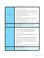
Storage
AMD
®
X370 Chipset
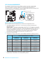
y 6x SATA 6Gb/s ports*
y 2x M.2 ports (Key M)
M2_1 slot supports PCIe 3.0 x4 (RYZEN series processor)
or PCIe 3.0 x2 (7th Gen A-series/ Athlon™ processors)
and SATA 6Gb/s 2242/ 2260 /2280/ 22110 storage devices
M2_2 slot supports PCIe 2.0 x4 and SATA 6Gb/s 2242/
2260 /2280 storage devices
y 1x U.2 port
Supports PCIe 3.0 x4 (RYZEN series processor) or PCIe
3.0 x2 (7th Gen A-series/ Athlon™ processors) NVMe
storage
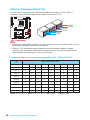
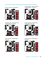
* Maximum support 2x M.2 PCIe SSDs + 6x SATA HDDs or 2x M.2 SATA SSDs +
4x SATA HDDs. Please refer to page 23 for M.2 slots with examples of various
combination possibilities.
Continued on next page

5
Specifications
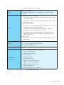
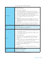
Continued from previous page
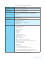
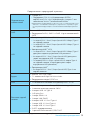
RAID
AMD
®
X370 Chipset
y Supports RAID 0, RAID 1 and RAID 10 for SATA storage
devices
USB
y ASMedia
®
ASM2142 Chipset
1x USB 3.1 Gen2 (SuperSpeed USB 10Gbps) Type-C port
on the back panel
1x USB 3.1 Gen2 (SuperSpeed USB 10Gbps) Type-A port
on the back panel
y AMD
®
X370 Chipset
1x USB 3.1 Gen2 (SuperSpeed USB 10Gbps) Type-C port
through the internal USB connector
4x USB 3.1 Gen1 (SuperSpeed USB) ports available
through the internal USB connectors
7x USB 2.0 (High-speed USB) ports (3 Type-A ports on
the back panel, 4 ports available through the internal
USB connectors)
y AMD
®
CPU
4x USB 3.1 Gen1 (SuperSpeed USB) Type-A ports on the
back panel
Audio
y Realtek
®
ALC1220 Codec
y 7.1-Channel High Definition Audio
y Supports S/PDIF output
LAN y 1x Intel
®
I211AT Gigabit LAN controller
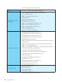
Back Panel
Connectors
y 1x PS/2 keyboard/ mouse combo port
y 1x Clear CMOS button
y 3x USB 2.0 Type-A ports
y 1x DisplayPort
y 1x HDMI
™
2.0 port
y 1x LAN (RJ45) port
y 4x USB 3.1 Gen1 Type-A ports
y 1x USB 3.1 Gen2 Type-A port
y 1x USB 3.1 Gen2 Type-C port
y 5x OFC audio jacks
y 1x Optical S/PDIF OUT connector
Continued on next page

6
Specifications
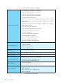
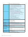
Continued from previous page
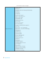
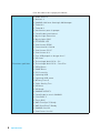
Internal Connectors
y 1x 24-pin ATX 12V power connector
y 1x 8-pin ATX 12V power connector
y 1x 4-pin ATX 12V power connector
y 1x 6-pin ATX 12V power connector
y 6x SATA 6Gb/s connectors
y 2x USB 2.0 connectors (support additional 4 USB 2.0 ports)
y 2x USB 3.1 Gen1 connectors (support additional 4 USB 3.1
Gen1 ports)
y 1x USB 3.1 Gen2 connector (supports additional 1 USB 3.1
Gen2 Type C port)
y 1x 4-pin CPU fan connector
y 1x 4-pin water-pump-fan connector
y 4x 4-pin system fan connectors
y 1x LED connector
y 1x 2-pin Slow mode connector
y 1x TPM module connector
y 1x Front panel audio connector
y 2x System panel connectors
y 1x Chassis Intrusion connector
Internal Buttons
y 1x Power button
y 1x Reset button
y 1x OC Genie button
y 1x Flash BIOS button
Jumper y 1x Clear CMOS jumper
Debug LED y 1x 2-Digit Debug Code LED
I/O Controller NUVOTON NCT6795D Controller Chip
Hardware Monitor
y CPU/System temperature detection
y CPU/System fan speed detection
y CPU/System fan speed control
Form Factor
y ATX Form Factor
y 12 in. x 9.6 in. (30.4 cm x 24.3 cm)
BIOS Features
y 1x 128 Mb flash
y UEFI AMI BIOS
y ACPI 5.0, PnP 1.0a, SM BIOS 2.8
y Multi-language
Continued on next page

7
Specifications
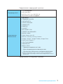
Continued from previous page
Software
y Drivers
y COMMAND CENTER
y LIVE UPDATE 6
y SUPER CHARGER
y GAMING APP
y RAMDISK
y X-BOOST
y MSI SMART TOOL
y GAMING LAN MANAGER
y Nahimic Audio
y XSplit Gamecaster V2
y Norton
™
Internet Security Solution
y Google Chrome
™
,Google Toolbar, Google Drive
y SteelSeries Engine 3
y CPU-Z MSI GAMING
y DRAGON EYE
y WTFast GPN*
2-Month Premium License
Multi-Server Network Optimization
Advanced Lag Spike & Disconnect Reduction
* This offer is valid for a limited period only, for more information please visit
www.msi.com
Continued on next page

8
Specifications
Continued from previous page
Special Features
y Audio Boost 4
y Nahimic 2
y GAMING LAN with Gaming LAN Manager
y Turbo U.2
y Turbo M.2
y Pump Fan
y Smart Fan Control
y Mystic Light Extension
y Mystic light SYNC
y EZ DEBUG LED
y DDR4 Steel Armor
y M.2 Shield
y PCI-E Steel Armor
y U.2 Steel Armor
y Golden Plated USB with type A+C
y VR Cover
y Multi GPU – SLI Technology
y Multi GPU – CrossFire Technology
y DDR4 Boost
y GAME Boost
y OC Essentials
y Lightning USB
y Front Lightning USB
y Military Class 5
y 7000+ Quality Test
y VR Boost
y VR Ready
y GAMING HOTKEY
y GAMING MOUSE Control
y Click BIOS 5
y Flash BIOS
y AMD FreeSync™ Ready
y AMD OverDrive™ Ready
y GAMING Certified
y SteelSeries Certified

9
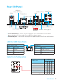
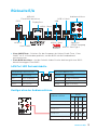
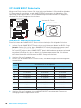
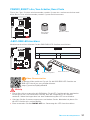
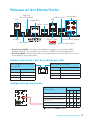
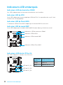
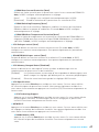
Rear I/O Panel
USB 3.1 Gen2 Type-C
Link/ Activity LED
Status Description
Off No link
Yellow Linked
Blinking Data activity
Speed LED
Status Description
Off 10 Mbps connection
Green 100 Mbps connection
Orange 1 Gbps connection
LAN Port LED Status Table
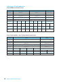
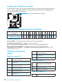
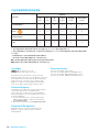
Audio Ports Configuration
Audio Ports
Channel
2 4 6 8
Center/ Subwoofer Out ● ●
Rear Speaker Out ● ● ●
Line-In/ Side Speaker Out ●
Line-Out/ Front Speaker Out ● ● ● ●
Mic In
(●: connected, Blank: empty)
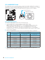
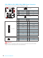
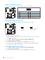
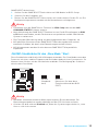
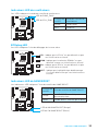
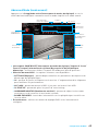
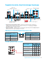
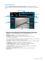
Rear I/O Panel
PS/2
LAN
USB 2.0
Audio Ports
Clear CMOS
Optical S/PDIF-Out
DisplayPort
USB 2.0/
Flash BIOS port
USB 3.1 Gen1
USB 3.1 Gen1
USB 3.1 Gen2
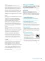
y Clear CMOS button - Power off your computer. Press and hold the Clear CMOS
button for about 5-10 seconds to reset BIOS to default values.
y Flash BIOS port - Please refer to page 39 for Updating BIOS with Flash BIOS Button.

10
Specifications
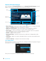
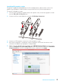
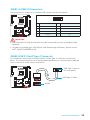
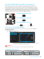
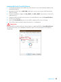
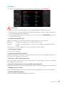
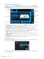
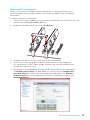
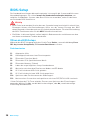
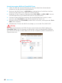
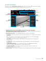
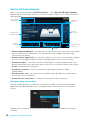
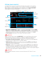
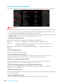
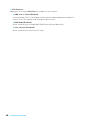
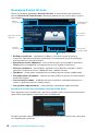
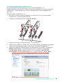
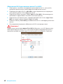
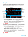
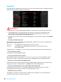
Realtek HD Audio Manager
After installing the Realtek HD Audio driver, the Realtek HD Audio Manager icon will
appear in the system tray. Double click on the icon to launch.
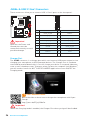
Jack Status
Device
Selection
Connector
Strings
Profiles
Main Volume
Application
Enhancement
Advanced
Settings
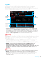
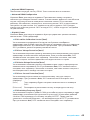
y Device Selection - allows you to select a audio output source to change the related
options. The check sign indicates the devices as default.
y Application Enhancement - the array of options will provide you a complete
guidance of anticipated sound effect for both output and input device.
y Main Volume - controls the volume or balance the right/left side of the speakers
that you plugged in front or rear panel by adjust the bar.
y Profiles - toggles between profiles.
y Advanced Settings - provides the mechanism to deal with 2 independent audio
streams.
y Jack Status - depicts all render and capture devices currently connected with your
computer.
y Connector Settings - configures the connection settings.
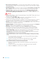
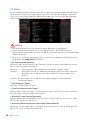
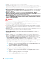
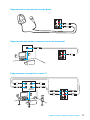
Auto popup dialog
When you plug into a device at an audio jack, a dialogue window will pop up asking you
which device is current connected.
Each jack corresponds to its default setting as shown on the next page.
Seite laden ...
Seite laden ...
Seite laden ...
Seite laden ...
Seite laden ...
Seite laden ...
Seite laden ...
Seite laden ...
Seite laden ...
Seite laden ...
Seite laden ...
Seite laden ...
Seite laden ...
Seite laden ...
Seite laden ...
Seite laden ...
Seite laden ...
Seite laden ...
Seite laden ...
Seite laden ...
Seite laden ...
Seite laden ...
Seite laden ...
Seite laden ...
Seite laden ...
Seite laden ...
Seite laden ...
Seite laden ...
Seite laden ...
Seite laden ...
Seite laden ...
Seite laden ...
Seite laden ...
Seite laden ...
Seite laden ...
Seite laden ...
Seite laden ...
Seite laden ...
Seite laden ...
Seite laden ...
Seite laden ...
Seite laden ...
Seite laden ...
Seite laden ...
Seite laden ...
Seite laden ...
Seite laden ...
Seite laden ...
Seite laden ...
Seite laden ...
Seite laden ...
Seite laden ...
Seite laden ...
Seite laden ...
Seite laden ...
Seite laden ...
Seite laden ...
Seite laden ...
Seite laden ...
Seite laden ...
Seite laden ...
Seite laden ...
Seite laden ...
Seite laden ...
Seite laden ...
Seite laden ...
Seite laden ...
Seite laden ...
Seite laden ...
Seite laden ...
Seite laden ...
Seite laden ...
Seite laden ...
Seite laden ...
Seite laden ...
Seite laden ...
Seite laden ...
Seite laden ...
Seite laden ...
Seite laden ...
Seite laden ...
Seite laden ...
Seite laden ...
Seite laden ...
Seite laden ...
Seite laden ...
Seite laden ...
Seite laden ...
Seite laden ...
Seite laden ...
Seite laden ...
Seite laden ...
Seite laden ...
Seite laden ...
Seite laden ...
Seite laden ...
Seite laden ...
Seite laden ...
Seite laden ...
Seite laden ...
Seite laden ...
Seite laden ...
Seite laden ...
Seite laden ...
Seite laden ...
Seite laden ...
Seite laden ...
Seite laden ...
Seite laden ...
Seite laden ...
Seite laden ...
Seite laden ...
Seite laden ...
Seite laden ...
Seite laden ...
Seite laden ...
Seite laden ...
Seite laden ...
Seite laden ...
Seite laden ...
Seite laden ...
Seite laden ...
Seite laden ...
Seite laden ...
Seite laden ...
Seite laden ...
Seite laden ...
Seite laden ...
Seite laden ...
Seite laden ...
Seite laden ...
Seite laden ...
Seite laden ...
Seite laden ...
Seite laden ...
Seite laden ...
Seite laden ...
Seite laden ...
Seite laden ...
Seite laden ...
Seite laden ...
Seite laden ...
Seite laden ...
Seite laden ...
Seite laden ...
Seite laden ...
Seite laden ...
Seite laden ...
Seite laden ...
Seite laden ...
Seite laden ...
Seite laden ...
Seite laden ...
Seite laden ...
Seite laden ...
Seite laden ...
Seite laden ...
Seite laden ...
Seite laden ...
Seite laden ...
Seite laden ...
Seite laden ...
Seite laden ...
Seite laden ...
Seite laden ...
Seite laden ...
Seite laden ...
Seite laden ...
Seite laden ...
Seite laden ...
Seite laden ...
Seite laden ...
Seite laden ...
Seite laden ...
Seite laden ...
Seite laden ...
Seite laden ...
Seite laden ...
Seite laden ...
Seite laden ...
Seite laden ...
Seite laden ...
Seite laden ...
Seite laden ...
Seite laden ...
Seite laden ...
Seite laden ...
Seite laden ...
Seite laden ...
Seite laden ...
Seite laden ...
Seite laden ...
-
 1
1
-
 2
2
-
 3
3
-
 4
4
-
 5
5
-
 6
6
-
 7
7
-
 8
8
-
 9
9
-
 10
10
-
 11
11
-
 12
12
-
 13
13
-
 14
14
-
 15
15
-
 16
16
-
 17
17
-
 18
18
-
 19
19
-
 20
20
-
 21
21
-
 22
22
-
 23
23
-
 24
24
-
 25
25
-
 26
26
-
 27
27
-
 28
28
-
 29
29
-
 30
30
-
 31
31
-
 32
32
-
 33
33
-
 34
34
-
 35
35
-
 36
36
-
 37
37
-
 38
38
-
 39
39
-
 40
40
-
 41
41
-
 42
42
-
 43
43
-
 44
44
-
 45
45
-
 46
46
-
 47
47
-
 48
48
-
 49
49
-
 50
50
-
 51
51
-
 52
52
-
 53
53
-
 54
54
-
 55
55
-
 56
56
-
 57
57
-
 58
58
-
 59
59
-
 60
60
-
 61
61
-
 62
62
-
 63
63
-
 64
64
-
 65
65
-
 66
66
-
 67
67
-
 68
68
-
 69
69
-
 70
70
-
 71
71
-
 72
72
-
 73
73
-
 74
74
-
 75
75
-
 76
76
-
 77
77
-
 78
78
-
 79
79
-
 80
80
-
 81
81
-
 82
82
-
 83
83
-
 84
84
-
 85
85
-
 86
86
-
 87
87
-
 88
88
-
 89
89
-
 90
90
-
 91
91
-
 92
92
-
 93
93
-
 94
94
-
 95
95
-
 96
96
-
 97
97
-
 98
98
-
 99
99
-
 100
100
-
 101
101
-
 102
102
-
 103
103
-
 104
104
-
 105
105
-
 106
106
-
 107
107
-
 108
108
-
 109
109
-
 110
110
-
 111
111
-
 112
112
-
 113
113
-
 114
114
-
 115
115
-
 116
116
-
 117
117
-
 118
118
-
 119
119
-
 120
120
-
 121
121
-
 122
122
-
 123
123
-
 124
124
-
 125
125
-
 126
126
-
 127
127
-
 128
128
-
 129
129
-
 130
130
-
 131
131
-
 132
132
-
 133
133
-
 134
134
-
 135
135
-
 136
136
-
 137
137
-
 138
138
-
 139
139
-
 140
140
-
 141
141
-
 142
142
-
 143
143
-
 144
144
-
 145
145
-
 146
146
-
 147
147
-
 148
148
-
 149
149
-
 150
150
-
 151
151
-
 152
152
-
 153
153
-
 154
154
-
 155
155
-
 156
156
-
 157
157
-
 158
158
-
 159
159
-
 160
160
-
 161
161
-
 162
162
-
 163
163
-
 164
164
-
 165
165
-
 166
166
-
 167
167
-
 168
168
-
 169
169
-
 170
170
-
 171
171
-
 172
172
-
 173
173
-
 174
174
-
 175
175
-
 176
176
-
 177
177
-
 178
178
-
 179
179
-
 180
180
-
 181
181
-
 182
182
-
 183
183
-
 184
184
-
 185
185
-
 186
186
-
 187
187
-
 188
188
-
 189
189
-
 190
190
-
 191
191
-
 192
192
-
 193
193
-
 194
194
-
 195
195
-
 196
196
-
 197
197
-
 198
198
-
 199
199
-
 200
200
-
 201
201
-
 202
202
-
 203
203
-
 204
204
-
 205
205
-
 206
206
-
 207
207
-
 208
208
-
 209
209
-
 210
210
-
 211
211
-
 212
212


MSI MS-7A31 Bedienungsanleitung
- Kategorie
- Motherboards
- Typ
- Bedienungsanleitung
- Dieses Handbuch ist auch geeignet für
in anderen Sprachen
- français: MSI MS-7A31 Le manuel du propriétaire
Verwandte Papiere
-
MSI MS-7A39v2.0 Benutzerhandbuch
-
-
MSI X370 GAMING M7 ACK Bedienungsanleitung
-
MSI X370 SLI PLUS Bedienungsanleitung
-
-
MSI MS-7A33 Bedienungsanleitung
-
MSI X370 GAMING PLUS Bedienungsanleitung
-
MSI MS-7A32 Bedienungsanleitung
-
-
MSI MS-7B79v1.0 Bedienungsanleitung