horntools HSW9940JIMII_X Bedienungsanleitung
- Typ
- Bedienungsanleitung

www.horntools.com
Einbauanleitung | Mounting instructions
Seilwinden Montagesatz Suzuki Jimny GJ | winch kit Suzuki Jimny Gj
Modell | Model
HSW9940JIMllPLATE
Beginne erst dann mit dem Einbau wenn du diese Anleitung komplett gelesen und verstanden hast!
Montagezeit: ca. 300 Minuten
Read this manual complete, do not start the installation until you fully understood the manual!
Installation duration: approximate 300 minutes

Datum / date: 2 | 1415.03.2023 Seite / page:
Technische Änderungen vorbehalten / technical changes reserved
Allgemeine Hinweise | universal notes
► Fragen / questions
Solltest du noch Fragen zur Montage oder zum Gebrauch deines Produktes haben, kontaktiere uns gerne.
If you have further questions regarding the mounting or the useage of your horntools product feel free to contact
us.
► Ersatzteile / spare parts
erhaltest du von deinem horntools Fachhändler /
contact your local horntools dealer
► Haftung / liability
Bei Nichtbeachtung der in dieser Anleitung angegebenen Hinweise und Informationen, bei nicht
bestimmungsgemäßem Gebrauch oder bei Einsatz außerhalb des vorgesehenen Verwendungszwecks, lehnt der
Hersteller die Gewährleistung für Schäden am Produkt ab.
Die Haftung für Folgeschäden an Elementen aller Art oder Personen ist ausgeschlossen. In case of non-
observance of this manual and its information or non-specied usage of the product, the manufacturer does not
give any kind of warranty of damage on the product.
The liability is excluded for consequential damages in any
kind for material or persons.
► Rechtliche hinweise / legal notice
Grak- und Textteile dieser Anleitung wurden mit Sorgfalt hergestellt. Für eventuell vorhandene Fehler und deren
Auswirkung kann keine Haftung übernommen werden! Technische Änderungen am Produkt sowie in dieser
Anleitung sind vorbehalten!
horntools excludes the liability for mistakes in the images or text phrases in this manual. Technical changes
reserved!
► Kennzeichnung von Gefahren / symbols for dangerous operation
Achtung! Dieses Symbol weist auf wichtige Arbeitsschritte hin, bei Nichtbeachtung kann es zu
Beschädigung am Produkt oder Verletzungen kommen!
Whenever this symbol is placed at an installation step special care must be taken. If you don’t
follow the instructions you could either damage the product or injure yourself!
► Nach dem Einbau / after the installation
Mach dich auf eine Testfahrt und prüfe ob durch den Einbau der horntools Komponente keine ungewollten
Geräusche entstanden sind oder sich das Fahrverhalten anderweitig geändert hat.
Make a test drive with the car and check that no unwanted noise or other unwanted changes in the cars
driveability or behaviour have occurred since you’ve installed the horntools components.
► Wichtig / important
Scanne diesen QR Code, um die Einbauanleitung auf deinem Smartphone zu önen.
Prüfe, ob die Versionsnummer (unten) dieselbe ist! Es kann sein, dass online bereits
eine aktualisierte Version (höherer Code) zur Verfügung steht – dann muss diese
verwendet werden.
Scan this QR Code to open this instruction on your mobile phone! Make sure that
the online and the printed instruction are the same version (code below)! It could be
possible that there is already an updated online version available.
If the version code of the online manual is higher than this one use the online manual!
Wenn du den QR Code nicht önen kannst hier der Link:
If you can’t read the QR Code we stated the link here:
https://www.horntools.com/pub/more_downloads/hsw9940jimllplate_ins_man_de_en.pdf
VERSION: V1.1

3 | 14
Seite / page:
Datum / date: 15.03.2023
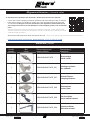
Stückliste | partlist
Anzahl
quantity
Bild
image
Zeichnungsnummer
drawing number
Beschreibung
description
1
HSW9940JIMllPLATE Windenträger
winch carrier
1
HSW9940JIMllPLATE_001 Abstützung hinten
rear stiener
2
HSW9940JIMllPLATE_007 Klemm Distanz
clamping distance
2
HSW9940JIMllPLATE_006 Distanzplatte
Spacer plate
1
HSW9940JIMllPLATE_008 Not Aus Halter
power switch bracket
1
HSW9940JIMllPLATE_009 Steuerbox Halter
relais box bracket
► Ausführliches Handbuch der Seilwinde / detailed horntools winch manual
Um dir den sicheren Umgang mit deiner Seilwinde und deren Wartung näher zu bringen
hat horntools eigens ein Handbuch erstellt. Der unten angeführte QR Code führt dich
zum Handbuch! Beginne nicht mit dem Einbau des Systemes und benütze keinen
der Komponenten bevor Du das Handbuch nicht komplett gelesen und verstanden
hast!
horntools designed a specic manual for the useage of winches. Follow the QR-code
below to access. Do not start the installation and do not use the winch before you totally
understood this document.
Wenn du den QR Code nicht önen kannst hier der Link: /
If you can’t read the QR Code we stated the link here:
https://www.horntools.com/pub/more_downloads/hsw9_12_ins_p_man_de_en.pdf
Allgemeine Hinweise | universal notes

Datum / date: 4 | 1415.03.2023 Seite / page:
Technische Änderungen vorbehalten / technical changes reserved
Schraubenliste | boltlist
Artikel
article
Größe
size
Festigkeit
strength
Koporm
head
Oberäche
surface DIN / ISO Stk.
quant.
Schraube / bolt M12 70 Sechskant
hex
verzinkt
galvanized DIN6921 2
Schraube / bolt M8 80 Sechskant
hex
verzinkt
galvanized DIN933 4
Scheibe / washer M8 verzinkt
galvanized DIN125-A 4
Schraube / bolt M8 25 Sechskant
hex
verzinkt
galvanized DIN6921 2
Scheibe / washer M8 verzinkt
galvanized DIN125-A 4
Mutter / nut M8 Sechskant
hex
verzinkt
galvanized DIN985 4
Schraube / bolt M8 50 Sechskant
hex
verzinkt
galvanized DIN6921 4
Scheibe / washer M8 verzinkt
galvanized DIN127-A 4
Scheibe / washer M8 verzinkt
galvanized DIN125-A 4
Schraube / bolt M8 25 Sechskant
hex
verzinkt
galvanized DIN933 4
Scheibe / washer M8 verzinkt
galvanized DIN125-A 2
Mutter / nut M8 Sechskant
hex
verzinkt
galvanized DIN985 2
Mutter / nut M8 Sechskant
hex
Edelstahl
stainless A2-70 DIN6923 2
Schraube / bolt M8 40 Sechskant
hex
Edelstahl
stainless A2-70 DIN6921 2
Schraube / bolt M5 10 Kreuzschlitz
philipps
verzinkt
galvanized DIN7985 2
Scheibe / washer M5 DIN125-A 2
Mutter / nut M12 Sechskant
hex
verzinkt
galvanized DIN6923 2
Schraube / bolt M8 verzinkt
galvanized
Bügel
U-bolt 2
Prüfe vor dem Einbau ob der Lieferumfang komplett ist und alle Teile unbeschädigt sind. Sollen Teile fehlen oder
beschädigt sein kontaktiere bitte deinen horntools Händler und warte mit dem Einbau des System bis alle Teile
unbeschädigt bei dir sind.
Before installing the winch check if all parts are in the package and are not damaged! If something is missing or
damaged contact your horntools dealer and don’t start the installation.

5 | 14
Seite / page:
Datum / date: 15.03.2023
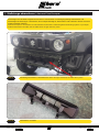
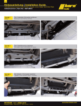
Stoßstange abmontieren | demount front bumper1.
Stoßstange laut Herstellervorgaben demontieren. Scheinwerfer und Reinigungsanlage abschließen und
Stoßstange bei Seite legen. Luftschacht, der mit Clips befestigt ist, demontieren und entfernen. Dieser wird nicht
weiterverwendet (Abb.02).
Demount bumper in accordance to manufacturers instructions. Detach lights and washing system. Lay bumper
aside and demount air bae, the air bae does not get used any more.
Luftschacht / air baeAbb.02
Stoßstange demontiert, Luftschacht am Auto / bumper detached, air bae still in placeAbb.01

Datum / date: 6 | 1415.03.2023 Seite / page:
Technische Änderungen vorbehalten / technical changes reserved
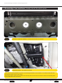
Abstützung hinten / rear stiener mountedAbb.04
Wie in Abb.04 gezeigt Abstützung hinten mit den Bügelschrauben lose einsetzen, die vordere Platte über die
gebördelten Kanten legen (roter Pfeil).
Like shown above insert the rear stiener and loosely bolt it to the rear most carrier. Orient the frontmost plate
over the dimpled holes (red arrow)
Windenträger lose montieren | loosely mount the winch carrier2.
Distanzen in Rahmen einführen / insert distance blocks in the frameAbb.03

7 | 14
Seite / page:
Datum / date: 15.03.2023
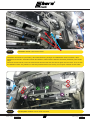
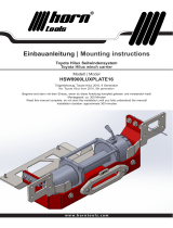
Stabilisator erhöht / anti roll bar raisedAbb.05
Stabilisator demontieren (rote Pfeile), dann Stabi Erhöhung einlegen und Stabilisator drauf schrauben, dafür
M8x50mm verwenden. Auf beiden Seiten durchführen, Darauf achten dass die Schraube (Pfeil blau) nach außen
zeigt!
Demount the anti-roll bar, insert the raiser blocks and then bolt the anti-roll bar again onto the raiser. To do so use
the M8x50mm bolts. Pay attention to the bolt (marked with the blue arrow), it must point outward on both sides.
Windenplatte montiert / winch carrier mountedAbb.06

Datum / date: 8 | 1415.03.2023 Seite / page:
Technische Änderungen vorbehalten / technical changes reserved
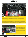
Winde, Seilfenster und Notaus platziert / winch, power switch and rope eyelet mountedAbb.07
Montieren Du das Seilfenster auf die M12 Stehbolzen und den Notaus Schalter (M8x40) auf das Halteblech, im
Anschluss das Halteblech auf die Stehbolzen am Windenträger.
Mount the eyelet to the M12 bolts and bolt the power switch to its bracket (M8x40), then x the bracket to the
winch carrier.
Windenträger lose befestigen, rote Kreise M8x80 mit Scheibe, grüne Kreise M12x70, violette Kreise M8x25.Im
Anschluss Winde auf dem Träger platzieren, alle Schrauben lose lassen damit sich die Winde platzieren lässt.
Dann Winde mit M8x25 Klasse 10.9 plus Unterleg- & Feder-Scheibe festziehen.
Place winch carrier like shown in abb.06. Loosely set the bolts, red circle M8x80 with washer, green circle
M12x70, violet circle M8x25. Then place the winch on the carrier like shown in Abb. 07.To x the winch in place
use the M8x25 bolts with strength class 10.9 with washer and feather washer.

9 | 14
Seite / page:
Datum / date: 15.03.2023
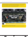
Halteblech Steuerbox Montagepunkte / relais box mounting pointsAbb.08
Schrauben der Winde wieder verschlossen / threads on winch closed with OEM boltsAbb.09
Nun alle Schrauben des Aufbaus mit
den entsprechenden Werten aus der
Drehmoment Tabelle auf der letzten Seite
festziehen. Alle Schraubverbindungen
periodisch mit angegebenem Drehmoment
nachziehen.
Now torque down all bolts according to
the torque diagram on the last page of this
manual.Periodically check the tightness of
all bolts!
Halteblech für die Steuerbox wird über die Schrauben des Motorsteuergerätes und einer Schraube in der
Spritzwand befestigt (Abb.09), mit den bestehenden Schraubenelementen. Dazu müssen die Schrauben
des Motorsteuergerät Haltebügels gelöst werden, dann das Halteblech der Steuerbox einführen und den
Motorsteuergerät Haltebügel wieder festschrauben. Steuerbox von der Winde abziehen, Halteblech von der
Winde demontieren und mit den Schrauben aus dem Set auf den Steuerboxhalter schrauben. Die Gewinde auf
der Oberseite der Winde mit den originalen Schrauben wieder schließen (Abb.09)
The bracket for the relais box gets bolted with the engine ECU and one bolt in the bulkhead. Loosen the ECU
bracket, then slide in the winch control box bracket. Fix the assembly with the OEM ECU bracket and the OEM
bolt nut from the bulkhead (positions shown in Abb.08). On top side of the winch pull of the relais box, unbolt the
bracket and bolt it on the relais box bracket with the bolts from the set. Use the OEM bolts to close the now open
threads on the winch (Abb.09).

Datum / date: 10 | 1415.03.2023 Seite / page:
Technische Änderungen vorbehalten / technical changes reserved
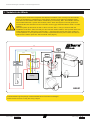
Verkabeln der Winde3.
Windensystem anhand des folgenden Schaltplanes verkabeln. Bat+ Leitung nicht anschließen
bevor die Verkabelung vollständig ist. Achte darauf, dass du keine Kabel beschädigst! Kabel
nicht über scharfe Kanten ziehen! Nach Verkabelung und Prüfung „Bat+“ anschließen und Not-
Aus Schalter aktivieren. System auf Funktion prüfen. Wenn das System nicht wie gewünscht
funktioniert Not-Aus Schalter trennen und Fehler suchen (ggf. Windenhandbuch Seite 2 zu Rate
ziehen).
Wire the system up like shown in Abb.10. Don’t connect “Bat +” until you are done with the
installation of all wires. Take care that you don’t hurt the cables isolation, don’t pull the cable over
sharp edges/corners. After wiring connect “Bat +”, activate power switch and check system for
correct operation. If the system doesn’t work like expected deactivate power switch and start to
search for the reason (look into “winch manual” from page 2).
Winde+
Winde-
Bat-
Not Aus
Bat +
Grün
Massepunk
KFZ
Stecker
3 polig
Funkfernbedienung
Empfänger
Braun
Rot
Blau
Schwarz
Gelb
Weiß
Antenne
Rot
H0051
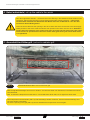
Funkfernbedienungs Empfänger mittels Kabelbinder an Steuerbox befestigen.
Fixate remote receiver to relay box using a zip tie.

11 | 14
Seite / page:
Datum / date: 15.03.2023
Der Kabelsatz mit dem Funkfernbedienungs Empfänger sieht so aus:
The wiring with the remote receiver looks like this:
Den Anschluss der Seilwinde anhand von unten stehender Tabelle durchführen:
For the electrical connection use the list below:
Beschreibung /
Description
Anschluss 1 /
Connection 1 Länge / Length Anschluss 2 /
Connection 2
Bat - /
Steuerbox 4600
control box 4600
M8 800mm M6
Bat + /
Notaus Schalter
emergency stop
M8 1100mm M10 GELB / YELLOW
Notaus Schalter
emergency stop /
Steuerbox 4600
control box 4600
M10 GELB / YELLOW 900mm M6
Steuerbox 4600
control box 4600 /
Winde +
winch +
M6 ROT / RED 900mm M6
Steuerbox 4600
control box 4600 /
Winde -
winch -
M6 BLAU / BLUE 1200mm M6

Datum / date: 12 | 1415.03.2023 Seite / page:
Technische Änderungen vorbehalten / technical changes reserved
Kabel aufwickeln | roll up the cable to the winch4.
Nun das mitgelieferte Winden – Kunststo Seil in die Önung in der Windentrommel einführen und
festziehen. Kabel gestreckt halten und mit Winde gleichmäßig verteilt aufspulen – nähere dich
niemals näher als 25cm zum Seilfenster der Winde wenn sie im Betrieb ist. Lass das Seil
nicht durch deine Hände gleiten!
Insert the winch cable into the opening in the winch drum and x the secure bolt in the drum.Apply
steady tension to the winch cable and wind it even spread on the drum onto the winch. Attention –
ensure that your hands do never come closer than 10 inches into the area of the rope eyelet
when winch is in operation! Also do never let the cable glide threw your hands while winch
is in operation!
Ausschnitt im Kühlergrill | cut out in radiator grill5.
Ausschnitt aus dem Grill / cutout of the front grillAbb.12
Abb.12 zeigt die Stoßstange aus Sicht von hinten! L für Links aus Sicht vom Fahrersitz, R für Rechts aus Sicht
vom Fahrersitz.
Abb. 12 shows the bumper from back side! “L” for left side from driver seat, “R” for right from driver seat.
Grill entsprechend ausschneiden (Abb.12) und Stoßstange wieder montieren, Scheinwerferwaschanlage und
Leuchten wieder anschließen.
Cut out the opening in the grill (Abb.12) and re assemble the bumper then mount it again.

13 | 14
Seite / page:
Datum / date: 15.03.2023
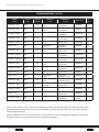
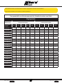
Vorspannkräfte und Anziemomente für Schaftschrauben aus Stahl
Regelgewinde
Abmessung Vorspannkraft (kN) Anziehmoment (Nm)
Festigkeits-
klasse 4.6 5.6 8.8 10.9 12.9 4.6 5.6 8.8 10.9 12.9
M 4x0,70 1,29 1,71 3,9 5,7 6,7 1,02 1,37 3,0 4,4 5,1
M 5x0,80 2,1 2,79 6,4 9,3 10,9 2,0 2,7 5,9 8,7 10
M 6x1,00 2,96 3,94 9,0 13,2 15,4 3,5 4,6 10,0 15,0 18,0
M 8x1,25 5,42 7,23 16,5 24,2 28,5 8,4 11,0 25,0 36,0 43,0
M 10x1,50 8,64 11,5 26,0 38,5 45,0 17,0 22,0 49,0 72,0 84,0
M 12x1,75 12,6 16,8 38,5 56,0 66,0 29,0 39,0 85,0 125,0 145,0
M 14x2,00 17,3 23,1 53,0 77,0 90,0 46,0 62,0 135,0 200,0 235,0
M 16x2,00 23,8 31,7 72,0 106,0 124,0 71,0 95,0 210,0 310,0 365,0
M 18x2,50 28,9 38,6 91,0 129,0 151,0 97,0 130,0 300,0 430,0 500,0
M 20x2,50 37,2 49,6 117,0 166,0 194,0 138,0 184,0 425,0 610,0 710,0
M 22x2,50 46,5 62,0 146,0 208,0 243,0 186,0 250,0 580,0 830,0 970,0
M 24x3,00 53,6 71,4 168,0 239,0 280,0 235,0 315,0 730,0 1050,0 1220,0
M 27x3,00 70,6 94,1 221,0 315,0 370,0 350,0 470,0 1100,0 1550,0 1800,0
M 30x3,50 85,7 114,5 270,0 385,0 450,0 475,0 635,0 1450,0 2100,0 2450,0
M 33x3,50 107,0 142,5 335,0 480,0 560,0 645,0 865,0 2000,0 2800,0 3400,0
M 36x4,00 125,5 167,5 395,0 560,0 680,0 1080,0 1440,0 2600,0 3700,0 4300,0
M 39x4,00 151,0 201,0 475,0 670,0 790,0 1330,0 1780,0 3400,0 4800,0 5600,0
Anzugsdrehmomente, alle Schrauben mit dem angegebenen Drehmoment anziehen.
Torque down all bolts in accordance to below guidelines

www.horntools.com
horntools GmbH
Wallenmahd 23 . 6850 Dornbirn . AUSTRIA
email: o[email protected]
UID: ATU65090439
-
 1
1
-
 2
2
-
 3
3
-
 4
4
-
 5
5
-
 6
6
-
 7
7
-
 8
8
-
 9
9
-
 10
10
-
 11
11
-
 12
12
-
 13
13
-
 14
14


horntools HSW9940JIMII_X Bedienungsanleitung
- Typ
- Bedienungsanleitung
in anderen Sprachen
Verwandte Artikel
-
 horntools HSW9940JIMIIPLATE Bedienungsanleitung
-
 horntools HUFJIMII04 Bedienungsanleitung
-
 horntools HUFJIMII14A Bedienungsanleitung
-
 horntools HPABACK03_X Bedienungsanleitung
-
 horntools HUFJIM12 Bedienungsanleitung
-
 horntools HSW9900TOHI16 Bedienungsanleitung
-
 horntools HSW9900RANGDY16_X Bedienungsanleitung
-
 horntools HSW9900JIM_X Bedienungsanleitung
-
 horntools HSW9900RANGDY_X Bedienungsanleitung
-
 horntools HSW9900IVDA_X Bedienungsanleitung


