horntools HSW9900TOHI16 Bedienungsanleitung
- Typ
- Bedienungsanleitung

www.horntools.com
Einbauanleitung | Mounting instructions
Toyota Hilux Seilwindensystem
Toyota Hilux winch carrier
Modell | Model
HSW9900LUXPLATE16
Trägerfahrzeug: Toyota Hilux 2016, 8 Generation
fits: Toyota Hilux from 2016, 8th generation
Beginne erst dann mit dem Einbau, wenn du diese Anleitung komplett gelesen und verstanden hast!
Montagezeit: ca. 300 Minuten
Read this manual complete, do not start the installation until you fully understood the manual!
Installation duration: approximate 300 minutes

Datum / date: 2 | 1626.02.2020 Seite / page:
Technische Änderungen vorbehalten / technical changes reserved
Allgemeine Hinweise | universal notes
► Fragen / questions
Solltest du noch Fragen zur Montage oder zum Gebrauch deines Produktes haben, kontaktiere uns gerne. If you
have further questions regarding the mounting or the useage of your horntools product feel free to contact us.
► Ersatzteile / spare parts
erhaltest du von deinem horntools Fachhändler / contact your local horntools dealer
► Haftung / liability
Bei Nichtbeachtung der in dieser Anleitung angegebenen Hinweise und Informationen, bei nicht
bestimmungsgemäßem Gebrauch oder bei Einsatz außerhalb des vorgesehenen Verwendungszwecks, lehnt der
Hersteller die Gewährleistung für Schäden am Produkt ab.
Die Haftung für Folgeschäden an Elementen aller Art oder Personen ist ausgeschlossen. In case of non-
observance of this manual and its information or non-specied usage of the product, the manufacturer does not
give any kind of warranty of damage on the product.
The liability is excluded for consequential damages in any kind for material or persons.
► Rechtliche hinweise / legal notice
Grak- und Textteile dieser Anleitung wurden mit Sorgfalt hergestellt. Für eventuell vorhandene Fehler und deren
Auswirkung kann keine Haftung übernommen werden! Technische Änderungen am Produkt sowie in dieser
Anleitung sind vorbehalten! horntools excludes the liability for mistakes in the images or text phrases in this
manual.
Technical changes reserved!
► Kennzeichnung von Gefahren / symbols for dangerous operation
Achtung! Dieses Symbol weist auf wichtige Arbeitsschritte hin, bei Nichtbeachtung kann es zu
Beschädigung am Produkt oder Verletzungen kommen! Whenever this symbol is placed at an
installation step special care must be taken. If you don’t follow the instructions you could either
damage the product or injure yourself!
► Nach dem Einbau / after the installation
Mach dich auf eine Testfahrt und prüfe ob durch den Einbau der horntools Komponente keine ungewollten
Geräusche entstanden sind oder sich das Fahrverhalten anderweitig geändert hat. Make a test drive with the car
and check that no unwanted noise or other unwanted changes in the cars driveability or behaviour have occurred
since you’ve installed the horntools components.
► Ausführliches Handbuch der Seilwinde / detailed horntools winch manual
Um dir den sicheren Umgang mit deiner Seilwinde und deren Wartung näher zu bringen hat horntools eigens ein
Handbuch erstellt. Der unten angeführte QR Code führt dich zum Handbuch!
Beginne nicht mit dem Einbau des Systemes und benütze keinen der
Komponenten bevor Du das Handbuch nicht komplett gelesen und verstanden
hast! horntools designed a specic manual for the useage of winches. Follow the QR-
code below to access. Do not start the installation and do not use the winch before
you totally understood this document.
https://www.horntools.com/download/HSW9_12_Ins_P_Man_DE.pdf

3 | 16
Seite / page:
Datum / date: 26.02.2020
Stückliste | partlist
Anzahl
quantity
Bild
image
Zeichnungsnummer
drawing number
Beschreibung
description
1
hsw9900luxplate Hauptplatte /
main bracket
1
hsw9900luxplate_skidplate Unterfahrschutz /
skid plate
2
hsw9900luxplate_front_
stiener
Versteifung /
stiener
2
hsw9900luxplate_boltplate Schraubplatte /
boltplate
1
hsw9900luxplate_bracket_
notaus
Notaushalter /
bracket for emergence stop
1
hsw9900luxplate_bracket_
controller
Fernbedienungshalter /
bracket for controller
1
hsw9900luxplate_bracket_
controlbox
Halter für Steuerbox /
Bracket for controlbox
4
hsw9900luxplate_shim Distanzstück /
shim

Datum / date: 4 | 1626.02.2020 Seite / page:
Technische Änderungen vorbehalten / technical changes reserved
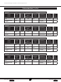
Hauptrahmen Verbindung main | frame connection
Artikel
article
Größe
size
Länge
length
Schrauben-
klasse
strength class
Koporm
head
Oberäche
surface nish
Norm
standard
Stk.
quant.
Schraube
bolt M12 40 10.9 Sechskant
hex
verzinkt
galavanized DIN933 8
Unterlegscheibe
washer M12 Verzinkt
galvanized EN14399-6 8
Schraubenliste | boltlist
Seilfenster | fairlead
Artikel
article
Größe
size
Länge
length
Schrauben-
klasse
strength class
Koporm
head
Oberäche
surface nish
Norm
standard
Stk.
quant.
Schraube
bolt M12 35 10.9 Sechskant
hex
verzinkt
galavanized DIN912 2
Unterlegscheibe
washer M12 verzinkt
galavanized DIN125-A 2
Unterfahrschutz | skid plate
Artikel
article
Größe
size
Länge
length
Schrauben-
klasse
strength class
Koporm
head
Oberäche
surface nish
Norm
standard
Stk.
quant.
Schraube
bolt M8 25 8.8 Sechskant
hex
verzinkt
galavanized DIN933 2
Schraube
bolt M8 35 8.8 Sechskant
hex
verzinkt
galavanized DIN933 2
Unterlegscheibe
washer M8 verzinkt
galavanized DIN9021 4
Verbindung zur Winde | winch connection
Artikel
article
Größe
size
Länge
length
Schrauben-
klasse
strength class
Koporm
head
Oberäche
surface nish
Norm
standard
Stk.
quant.
Schraube
bolt M10 35 10.9 Sechskant
hex
verzinkt
galavanized DIN933 4
Unterlegscheibe
washer M10 verzinkt
galavanized DIN7349 4

5 | 16
Seite / page:
Datum / date: 26.02.2020
Kontrollbox | controlbox
Artikel
article
Größe
size
Länge
length
Schrauben-
klasse
strength class
Koporm
head
Oberäche
surface nish
Norm
standard
Stk.
quant.
Schraube
bolt M6 20 8.8 Sechskant
hex
verzinkt
galavanized DIN933 3
Mutter
nut M6 verzinkt
galavanized ISO7040 2
Unterlegscheibe
washer M6 verzinkt
galavanized DIN125-A 5
Hauptschalter | powerswitch
Artikel
article
Größe
size
Länge
length
Schrauben-
klasse
strength class
Koporm
head
Oberäche
surface nish
Norm
standard
Stk.
quant.
Schraube
bolt M8 25 8.8 Sechskant
hex
verzinkt
galavanized DIN933 2
Schraube
bolt M8 50 8.8 Sechskant
hex
verzinkt
galavanized DIN933 2
Unterlegscheibe
washer M8 verzinkt
galavanized DIN125-A 6
Mutter
nut M8 verzinkt
galavanized ISO7040 2
Fernbedienung | remotecontrol
Artikel
article
Größe
size
Länge
length
Schrauben-
klasse
strength class
Koporm
head
Oberäche
surface nish
Norm
standard
Stk.
quant.
Schraube
bolt M8 20 8.8 Sechskant
hex
verzinkt
galavanized DIN933 1
Mutter
nut M8 verzinkt
galavanized ISO7040 1
Unterlegscheibe
washer M8 verzinkt
galavanized DIN125-A 1
Prüfe vor dem Einbau ob der Lieferumfang komplett ist und alle Teile unbeschädigt sind.
Sollten Teile fehlen oder beschädigt sein kontaktiere bitte deinen horntools Händler und warte mit dem
Einbau des Systems bis alle Teile unbeschädigt bei dir sind.
Before installing the horntools product, check if all parts are in the package and are not damaged!
If something is missing or damaged contact your horntools dealer and don’t start the installation.

Datum / date: 6 | 1626.02.2020 Seite / page:
Technische Änderungen vorbehalten / technical changes reserved
Einbauanleitung | manual
1. Im ersten Schritt muss die Frontstoßstange und der vordere Unterfahrschutz, laut Herstellervorgaben,
demontiert werden. ACHTUNG! Das Auto so gerade wie möglich anheben, bevorzugt auf einer vier
Säulen Bühne, da es sonst zu Problemen führen kann.
In the rst step, the front bumper, as well as the OEM front skid plate, must be removed according to the
manufacturer‘s instructions. CAUTION! Raise the car as straight as possible, preferably on a four-pillar
lift, otherwise it can cause problems.
2. Jetzt wird der vordere Teil der Aufprallschutzes demontiert. Dafür muss der rechts außensitzende
Befestigungsclip entfernt werden. Abb. 1-2
Now the front part of the impact bar needs to be removed. To do this, the fastening clip on the right
outside must be removed. Abb. 1-2
Abb. 1: Befestigungsclip / fastening clip Abb. 2: entfernter Befestigungsclip / removed
fastening clip
Anschließend muss der vordere Teil des Aufprallschutzes nach Links gezogen werden Abb. 3-4.
Then the front part of the impact bar must be pulled to the left Abb. 3-4.

7 | 16
Seite / page:
Datum / date: 26.02.2020
Abb. 3: vordere Aufprallschutz / front part of the
impact bar
Abb. 4: entfernter vordere Aufprallschutz /
removed front impact bar
3. Nun kann der Hauptteil des Aufprallschutzes entfernt werden, dafür müssen die vier markierten
Schrauben gelöst werden Abb. 5.
Now the main part of the impact bar can be removed, for this the four marked screws must be loosened
Abb. 5.
Abb. 5: markierte Schrauben / marked bolts

Datum / date: 8 | 1626.02.2020 Seite / page:
Technische Änderungen vorbehalten / technical changes reserved
4. Jetzt können die Schraubplatte, in den markierten Önungen, in den Rahmen platziert werden Abb. 6-8.
Now the boltplates can be placed in the marked openings in the frame Abb. 6-8.
Abb. 6: markierte Löcher / marked holes
Abb. 7: Bolzenplatte einführen / insert boltplate
Abb. 8: platzierte Bolzenplatte / placed boltplate

9 | 16
Seite / page:
Datum / date: 26.02.2020
5. Nun kann die Hauptplatte zwischen den Rahmen platziert und mit den sechs Schrauben lose befestigt
werden Abb. 9-11. Falls nötig, die beigelegten Distanzstücke verwenden.
Now the main plate can be placed between the frame, then bolt the plate, with the six bolts, loosely to the
frame Abb. 9-11. If necessary, use included the shims.
Abb. 9: platzierte Hauptplatte / placed main plate
Abb. 10: Befestigung Hauptplatte links /
mounting main plate left
Abb. 11: Befestigung Hauptplatte recht /
mounting main plate right

Datum / date: 10 | 1626.02.2020 Seite / page:
Technische Änderungen vorbehalten / technical changes reserved
6. Jetzt wird der neue Unterfahrschutz, an den originalen Punkten, montiert Abb.12.
ACHTUNG! Der Unterfahrschutz wird über die Hauptplatte geschoben.
Now the new skid plate is installed using the original mounting points Abb. 12.
CAUTION! The skid plate is pushed over the main plate.
Abb. 12: Befestigung Unterfahrschutz / mounting skid plate
7. Nun können die Schrauben, welche die Hauptplatte von unten halten, lose platziert und angezogen
werden Abb. 13-14.
Now the screws, holding the main plate from below, can be placed and loosely tightened Abb. 13-14.
Abb. 13: Befestigung Hauptplatten, unten links /
mounting main plate, bottom left
Abb. 14: Befestigung Hauptplatten, unten rechts /
mounting main plate, bottom right

11 | 16
Seite / page:
Datum / date: 26.02.2020
8. Jetzt kann die Winde montiert werden. ACHTUNG! Es ist zu empfehlen jedes Kabel zuerst an die
Winde anzuschließen, bevor die Winde mit der Windenplatte verschraubt wird. Bei Montage der Kabel,
Kontermutter gegenhalten, sonst können Schäden an der Winde entstehen! Anzugsmoment 12Nm!
The winch can now be installed. CAUTION! It is recommended to rst mount all cables to the winch,
before bolting the winch to the winch plate. Hold the lock nut when installing the cables, otherwise the
winch may be damaged! Torque 12Nm!
9. In diesem Schritt müssen die originalen Halter des Unterfahrschutzes, welche sich auf dem
Aufprallschutz benden, modiziert werden Abb. 15. Hierfür müssen die markierten Halter abgeschnitten
werden, danach muss der Träger mit einem Zinkspray (oder ähnlichem) behandelt werden, um ihn vor
Korrosion zu schützen.
In this step, the original brackets for the OEM skid plate, which are located on the impact bar, must be
modied Abb. 15. For this, the marked brackets must be cut o, then the carrier must be treated with a
zinc spray (or similar) to protect it from corrosion.
Abb. 15: platzierte Hauptplatte / placed main plate

Datum / date: 12 | 1626.02.2020 Seite / page:
Technische Änderungen vorbehalten / technical changes reserved
10. Jetzt können die vorderen Versteifungen mit dem Seilwindensystem verschraubt werden Abb. 16-17.
Now the front stieners can be screwed to the winch system Abb. 16-17.
Abb. 16: Befestigung Versteifung mit Winden-
platte links / mounting stiener, left side
Abb. 17: Befestigung Versteifung mit Winden-
platte rechts / mounting stiener, right side
11. Danach wird der modizierte Aufprallschutz wieder mit dem Rahmen verschraubt, dazu werden die
originalen Schrauben verwendet Abb.18.
Then the modied impact bar is screwed back to the frame using the OEM screws Abb. 18.
Abb. 18: Befestigung Aufprallschutz / mounting impact bar

13 | 16
Seite / page:
Datum / date: 26.02.2020
12. Nun kann der vordere Teil des Aufprallschutzes wieder verbaut werden (siehe Schritt Nr.2).
Now the front part of the impact bar can be installed again (see step no.2).
13. Die Steuerbox an der Beifahrerseite, unter dem Frontscheinwerfer, montiert Abb. 19.
The control box is installed on the passenger side, under the headlight Abb. 19.
Abb. 19: Befestigung Steuerbox / mounting control box
14. Der Notaus wird unter dem Kühler verschraubt Abb. 20.
The emergency stop is screwed under the radiator Abb. 20.
15. Die Fernbedienung Halterung wird auf der Beifahrerseite, in der Nähe des Frontscheinwerfers, montiert
Abb. 21.
The remote-control bracket is mounted on the passenger side, near the headlight Abb. 21.

Datum / date: 14 | 1626.02.2020 Seite / page:
Technische Änderungen vorbehalten / technical changes reserved
Abb. 20: Befestigung Notaus/ mounting
emergency stop
Abb. 21: Befestigung Fernbedienunghalter/
mounting bracket for controller
16. Bevor die Stoßstange wieder montiert werden kann, müssen folgende Schnitte durchgeführt werden
Abb. 22.
The following cut-outs must be made, before the bumper is reinstalled Abb. 22.
Abb. 22: empfohlener Ausschnitt der Stoßstange/ recommended cut for the bumper
17. Kontrolliere, ob alle Schrauben laut Drehmomenttabelle (letzte Seite) festgezogen wurden, danach kann
die Stoßstange wieder montiert werden.
Check that all screws have been tightened according to the torque table (last page), then the bumper can
be reinstalled.

15 | 16
Seite / page:
Datum / date: 26.02.2020
Schaltplan | wiring diagram
Windensystem anhand des folgenden Schaltplans verkabeln. Bat+ Leitung NICHT
anschließen, bevor die Verkabelung vollständig ist! Achte darauf, dass du keine Kabel
beschädigst! Kabel nicht über scharfe Kanten ziehen und von rotierenden Teilen fernhalten!
Nach Verkabelung und Prüfung „Bat+“ anschließen, Not-Aus Schalter aktiveren und
Funktion prüfen. Wenn das System nicht wie gewünscht funktioniert Not- Aus Schalter
trennen und Fehler suchen.
Wire the winch system using the following circuit diagram. DO NOT connect the Bat + line
until the wiring is complete! Make sure you don‘t damage any cables! Do not pull the cable
over sharp edges and keep it away from rotating parts! After wiring and checking, connect
„Bat +“, activate the emergency stop switch and check the function. If the system does not
work as desired, disconnect the emergency stop switch and search for errors.

www.horntools.com
horntools GmbH
Wallenmahd 23 . 6850 Dornbirn . AUSTRIA
email: o[email protected]
UID: ATU65090439
Regelgewinde
Abmessung Vorspannkraft (kN) Anziehmoment (Nm)
Festigkeits-
klasse 4.6 5.6 8.8 10.9 12.9 4.6 5.6 8.8 10.9 12.9
M 4x0,70 1,29 1,71 3,9 5,7 6,7 1,02 1,37 3,0 4,4 5,1
M 5x0,80 2,1 2,79 6,4 9,3 10,9 2,0 2,7 5,9 8,7 10
M 6x1,00 2,96 3,94 9,0 13,2 15,4 3,5 4,6 10,0 15,0 18,0
M 8x1,25 5,42 7,23 16,5 24,2 28,5 8,4 11,0 25,0 36,0 43,0
M 10x1,50 8,64 11,5 26,0 38,5 45,0 17,0 22,0 49,0 72,0 84,0
M 12x1,75 12,6 16,8 38,5 56,0 66,0 29,0 39,0 85,0 125,0 145,0
M 14x2,00 17,3 23,1 53,0 77,0 90,0 46,0 62,0 135,0 200,0 235,0
M 16x2,00 23,8 31,7 72,0 106,0 124,0 71,0 95,0 210,0 310,0 365,0
M 18x2,50 28,9 38,6 91,0 129,0 151,0 97,0 130,0 300,0 430,0 500,0
M 20x2,50 37,2 49,6 117,0 166,0 194,0 138,0 184,0 425,0 610,0 710,0
M 22x2,50 46,5 62,0 146,0 208,0 243,0 186,0 250,0 580,0 830,0 970,0
M 24x3,00 53,6 71,4 168,0 239,0 280,0 235,0 315,0 730,0 1050,0 1220,0
M 27x3,00 70,6 94,1 221,0 315,0 370,0 350,0 470,0 1100,0 1550,0 1800,0
M 30x3,50 85,7 114,5 270,0 385,0 450,0 475,0 635,0 1450,0 2100,0 2450,0
M 33x3,50 107,0 142,5 335,0 480,0 560,0 645,0 865,0 2000,0 2800,0 3400,0
M 36x4,00 125,5 167,5 395,0 560,0 680,0 1080,0 1440,0 2600,0 3700,0 4300,0
M 39x4,00 151,0 201,0 475,0 670,0 790,0 1330,0 1780,0 3400,0 4800,0 5600,0
Drehmomenttabelle | torque diagram [torque in Nm]
-
 1
1
-
 2
2
-
 3
3
-
 4
4
-
 5
5
-
 6
6
-
 7
7
-
 8
8
-
 9
9
-
 10
10
-
 11
11
-
 12
12
-
 13
13
-
 14
14
-
 15
15
-
 16
16


horntools HSW9900TOHI16 Bedienungsanleitung
- Typ
- Bedienungsanleitung
in anderen Sprachen
Verwandte Artikel
-
 horntools HFORASPGE01 Bedienungsanleitung
-
 horntools HFORASPEN01 Bedienungsanleitung
-
 horntools HISDMSPAB01 Bedienungsanleitung
-
 horntools HISDMSPENA01 Bedienungsanleitung
-
 horntools HSW9940JIMII_X Bedienungsanleitung
-
 horntools HSW9900IVDA_X Bedienungsanleitung
-
 horntools HPABACK03_X Bedienungsanleitung
-
 horntools HSW9900RANGDY16_X Bedienungsanleitung
-
 horntools HSW9900JIM_X Bedienungsanleitung
-
 horntools HFORASPAB01 Bedienungsanleitung


