
Interior Systems
Handbuch
Manual
pureKNX-Serie
pureKNX series
Version 1.0
Artikel-Nr./Part-No.: 15665

Ludwig-Rinn-Straße 10-14 • D- 35452 Heuchelheim/Gießen • Phone: +49 6 41-9 62 84-0 • Fax: +49 6 41-9 62 84-28 • www.tci.de Ludwig-Rinn-Straße 10-14 • D- 35452 Heuchelheim/Gießen • Phone: +49 6 41-9 62 84-0 • Fax: +49 6 41-9 62 84-28 • www.tci.de
Seite 2 von 78 Seite 3 von 78
Inhaltsverzeichnis
1. HAFTUNG/COPYRIGHT . . . . . . . . . . . . . . . . . . . . . . . . . . . . . . . 6
2. BEVOR SIE BEGINNEN
2.1 WILLKOMMEN . . . . . . . . . . . . . . . . . . . . . . . . . . . . . . . . . . 8
2.2 SICHERHEIT . . . . . . . . . . . . . . . . . . . . . . . . . . . . . . . . . . . 8
2.3 SICHERHEITSHINWEISE . . . . . . . . . . . . . . . . . . . . . . . . . . . . .10
3. PRODUKTBESCHREIBUNG
3.1 PRODUKTDEFINITION . . . . . . . . . . . . . . . . . . . . . . . . . . . . . .14
3.2 TECHNISCHE DATEN . . . . . . . . . . . . . . . . . . . . . . . . . . . . . .16
3.3 SCHNITTSTELLEN UND SENSOREN
3.31 PUREKNX-BASE7 . . . . . . . . . . . . . . . . . . . . . . . . . . . . . . .22
3.32 PUREKNX-LINE . . . . . . . . . . . . . . . . . . . . . . . . . . . . . . . .24
3.33 PUREKNX-LINE IM KONFERENZTISCHGEHÄUSE (KTG) . . . . . . . . . . .26
3.34 PUREKNX-TREND . . . . . . . . . . . . . . . . . . . . . . . . . . . . . . .28
3.35 PUREKNX-TREND IM KONFERENZTISCHGEHÄUSE (KTG) . . . . . . . . .30
3.4 EINBAU DES PUREKNX . . . . . . . . . . . . . . . . . . . . . . . . . . . . .32
3.41 PUREKNX-BASE . . . . . . . . . . . . . . . . . . . . . . . . . . . . . . . .34
3.42 EINBAU DES PUREKNX-LINE & -TREND IN DAS UPG/EPG . . . . . . . . .36
3.43 MONTAGE DES PUREKNX-LINE & -TREND IM APG . . . . . . . . . . . . .38
3.44 MONTAGE DES PUREKNX-LINE & -TREND IM KTG . . . . . . . . . . . . .39
3.5 ENDMONTAGE/REINIGUNG . . . . . . . . . . . . . . . . . . . . . . . . . . .41
4. LIEFERUMFANG . . . . . . . . . . . . . . . . . . . . . . . . . . . . . . . . . . .42
5. SUPPORT
5.1 SUPPORT . . . . . . . . . . . . . . . . . . . . . . . . . . . . . . . . . . . . .44
5.2 RÜCKSENDNUNG . . . . . . . . . . . . . . . . . . . . . . . . . . . . . . . .44
5.3 HERSTELLERGARANTIE . . . . . . . . . . . . . . . . . . . . . . . . . . . . .46
6. WEITERE DOKUMENTATION . . . . . . . . . . . . . . . . . . . . . . . . . . . . .48
7. TECHNISCHE ZEICHNUNG
7.1 PUREKNX-BASE7 . . . . . . . . . . . . . . . . . . . . . . . . . . . . . . . .50
7.2 PUREKNX-LINE7, PUREKNX-TREND7 . . . . . . . . . . . . . . . . . . . . . .52
7.3 PUREKNX-LINE10, PUREKNX-TREND10 . . . . . . . . . . . . . . . . . . . .54
7.4 PUREKNX-LINE16, PUREKNX-TREND16 . . . . . . . . . . . . . . . . . . . .56
Table of Content
1. LIABILITY / COPYRIGHT . . . . . . . . . . . . . . . . . . . . . . . .7
2. BEFORE YOU BEGIN
2.1 WELCOME . . . . . . . . . . . . . . . . . . . . . . . . . . . .9
2.2 SAFETY . . . . . . . . . . . . . . . . . . . . . . . . . . . . .9
2.3 SAFETY INSTRUCTIONS . . . . . . . . . . . . . . . . . . . . . 11
3. PRODUCT DESCRIPTION
3.1 PRODUCT DEFINITION . . . . . . . . . . . . . . . . . . . . . . 15
3.2 TECHNICAL DATA . . . . . . . . . . . . . . . . . . . . . . . . 17
3.3 INTERFACES AND SENSORES
3.31 PUREKNX-BASE7 . . . . . . . . . . . . . . . . . . . . . . . 23
3.32 PUREKNX-LINE . . . . . . . . . . . . . . . . . . . . . . . . 25
3.33 PUREKNX-LINE IN A CONFERENCE TABLE HOUSING (KTG) . . . . . . 27
3.34 PUREKNX-TREND . . . . . . . . . . . . . . . . . . . . . . . 29
3.35 PUREKNX-TREND IN A CONFERENCE TABLE HOUSING (KTG) . . . . . 31
3.4 ASSEMBLING THE PUREKNX . . . . . . . . . . . . . . . . . . . 32
3.41 PUREKNX-BASE . . . . . . . . . . . . . . . . . . . . . . . 35
3.42 MOUNTING THE PUREKNX-LINE & -TREND INTO ITS UPG/EPG . . . . 36
3.43 MOUNTING THE PUREKNX-LINE & -TREND IN THE APG . . . . . . . 38
3.44 MOUNTING THE PUREKNX-LINE & -TREND IN THE KTG . . . . . . . 39
3.5 FINAL ASSEMBLY/CLEANING . . . . . . . . . . . . . . . . . . . 41
4. SCOPE OF DELIVERY . . . . . . . . . . . . . . . . . . . . . . . . . 43
5. SUPPORT
5.1 SUPPORT . . . . . . . . . . . . . . . . . . . . . . . . . . . 45
5.2 DISPATCH . . . . . . . . . . . . . . . . . . . . . . . . . . . 45
5.3 MANUFACTURER‘S GUARANTEE . . . . . . . . . . . . . . . . . 47
6. FURTHER DOCUMENTATION . . . . . . . . . . . . . . . . . . . . . 49
7. TECHNICAL DRAWING
7.1 PUREKNX-BASE7 . . . . . . . . . . . . . . . . . . . . . . . . 50
7.2 PUREKNX-LINE7, PUREKNX-TREND7 . . . . . . . . . . . . . . . . 52
7.3 PUREKNX-LINE10, PUREKNX-TREND10 . . . . . . . . . . . . . . . 54
7.4 PUREKNX-LINE16, PUREKNX-TREND16 . . . . . . . . . . . . . . . 56

Ludwig-Rinn-Straße 10-14 • D- 35452 Heuchelheim/Gießen • Phone: +49 6 41-9 62 84-0 • Fax: +49 6 41-9 62 84-28 • www.tci.de Ludwig-Rinn-Straße 10-14 • D- 35452 Heuchelheim/Gießen • Phone: +49 6 41-9 62 84-0 • Fax: +49 6 41-9 62 84-28 • www.tci.de
Seite 4 von 78 Seite 5 von 78
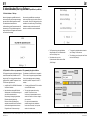
8. INBETRIEBNAHME SOFTWARE (PUREKNX-BASE & PUREKNX-LINE)
8.1 INBETRIEBNAHME . . . . . . . . . . . . . . . . . . . . . . . . . . . . . . . .58
8.2 PHYSIKALISCHE ADRESSE PROGRAMMIEREN . . . . . . . . . . . . . . . .58
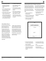
8.3 RESET BEI FEHLERN . . . . . . . . . . . . . . . . . . . . . . . . . . . . . .60
8.4 NETZWERKSCHNITTSTELLE EINRICHTEN . . . . . . . . . . . . . . . . . . .61
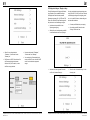
8.5 DISPLAYEINSTELLUNGEN . . . . . . . . . . . . . . . . . . . . . . . . . . . .63
8.6 SCREEN BRIGHTNESS . . . . . . . . . . . . . . . . . . . . . . . . . . . . .65
8.7 DISPLAY ORIENTATION . . . . . . . . . . . . . . . . . . . . . . . . . . . . .65
8.8 OTHERS . . . . . . . . . . . . . . . . . . . . . . . . . . . . . . . . . . . . .65
8.9 FIRMWAREUPDATE . . . . . . . . . . . . . . . . . . . . . . . . . . . . . . .66
9. INBETRIEBNAHME SOFTWARE (PUREKNX-TREND)
9.1 INBETRIEBNAHME . . . . . . . . . . . . . . . . . . . . . . . . . . . . . . . .70
9.2 KNX-SERVER CONTROL . . . . . . . . . . . . . . . . . . . . . . . . . . . . .71
9.21 SETTINGS-MENÜ (5) . . . . . . . . . . . . . . . . . . . . . . . . . . . . . .72
11. SOFTWARE
11.1 FUNKTIONSUMFANG . . . . . . . . . . . . . . . . . . . . . . . . . . . . . .76
12. FAQ . . . . . . . . . . . . . . . . . . . . . . . . . . . . . . . . . . . . . . . . . .77
8. START-UP SOFTWARE (PUREKNX-BASE & PUREKNX-LINE)
8.1 START-UP . . . . . . . . . . . . . . . . . . . . . . . . . . . 58
8.2 PROGRAMMING THE PHYSICAL ADDRESS . . . . . . . . . . . . . 58
8.3 ERROR RESET . . . . . . . . . . . . . . . . . . . . . . . . . 60
8.4 SETTING UP THE NETWORK INTERFACE . . . . . . . . . . . . . . 61
8.5 DISPLAY SETTINGS . . . . . . . . . . . . . . . . . . . . . . . 63
8.6 SCREEN BRIGHTNESS . . . . . . . . . . . . . . . . . . . . . . 65
8.7 DISPLAY ORIENTATION . . . . . . . . . . . . . . . . . . . . . 65
8.8 OTHERS . . . . . . . . . . . . . . . . . . . . . . . . . . . . 65
8.9 FIRMWARE UPDATE . . . . . . . . . . . . . . . . . . . . . . . 66
9. START-UP SOFTWARE (PUREKNX-TREND)
9.1 START-UP . . . . . . . . . . . . . . . . . . . . . . . . . . . 70
9.2 KNX-SERVER CONTROL . . . . . . . . . . . . . . . . . . . . . 71
9.21 SETTINGS MENU (5) . . . . . . . . . . . . . . . . . . . . . . 72
11. SOFTWARE
11.1 RANGE OF FUNCTIONS . . . . . . . . . . . . . . . . . . . . . 76
12. FAQ . . . . . . . . . . . . . . . . . . . . . . . . . . . . . . . 77

Ludwig-Rinn-Straße 10-14 • D- 35452 Heuchelheim/Gießen • Phone: +49 6 41-9 62 84-0 • Fax: +49 6 41-9 62 84-28 • www.tci.de Ludwig-Rinn-Straße 10-14 • D- 35452 Heuchelheim/Gießen • Phone: +49 6 41-9 62 84-0 • Fax: +49 6 41-9 62 84-28 • www.tci.de
Seite 6 von 78 Seite 7 von 78
1. Haftung / Copyright
Copyright tci GmbH, Ludwig-Rinn-Str. 10-14, 35452 Heuchelheim,
Deutschland
Dieses Handbuch, sowie die Hard- und Software, die es
beschreibt, ist urheberrechtlich geschützt und darf ohne
ausdrückliche schriftliche Genehmigung der tci GmbH in keiner
Weise vervielfältigt, übersetzt oder in eine andere Darstellungs-
form gebracht werden.
Warenzeichen Windows, Windows XP embedded, Windows 7 embedded und
Windows 10 IoT sind eingetragene Warenzeichen der Microsoft
Corp.
Diejenigen Bezeichnungen in dieser Publikation von Erzeugnissen
und Verfahren, die zugleich Warenzeichen sind, wurden nicht
besonders kenntlich gemacht. Solche Namen sind Warenzeichen
der jeweiligen Warenzeicheninhaber. Aus dem Fehlen der Markie-
rung ® kann nicht geschlossen werden, dass diese Bezeichnun-
gen freie Warennamen sind.
Hinweis Herausgeber, Übersetzer und Autoren dieser Publikation haben
mit größter Sorgfalt die Texte, Abbildungen und Programme
erarbeitet. Dennoch können Fehler nicht völlig ausgeschlossen
werden. Die tci GmbH übernimmt daher weder eine Garantie
noch eine juristische Verantwortung oder Haftung für Folgen, die
auf fehlerhafte Angaben zurückgehen. Mitteilungen über
eventuelle Fehler werden jederzeit gerne entgegengenommen.
Die Angaben in diesem Handbuch gelten nicht als Zusicherung
bestimmter Produkteigenschaften. Änderungen, die dem
technischen Fortschritt dienen, bleiben vorbehalten.
Haftung Die tci GmbH haftet nicht für unmittelbare Schäden, die im
Zusammenhang mit der Lieferung oder dem Gebrauch der
Dokumentation stehen. Wir haften zudem auch nicht für etwaige
Fehler in dieser Publikation. Wir verpflichten uns in keiner Weise,
die in dieser Dokumentation enthaltenen Informationen auf den
aktuellsten Stand zu bringen oder auf dem neuesten Stand zu
halten.
Alle Rechte vorbehalten • Printed in Germany
Gedruckt auf chlorfrei gebleichtem Papier.
1. Liability / Copyright
Copyright tci GmbH, Ludwig-Rinn-Str. 10-14, D-35452 Heuchelheim,
Germany
This manual, as well as the hard and software, which it describes
is protected by copyright and may not be duplicated, translated or
presented in any form without the written consent of tci GmbH.
Trademark Windows, Windows XP embedded, Windows 7 embedded and
Windows 10 IoT are registered trademarks of Microsoft Corp.
Those designation of products and procedures in this publication,
which are also trademarks, have not been expressly stated as
such. These names are trademarks of the respective trademark
owners. However, the absence of the ® symbol, implies in no way
that the designations are exempt from such rights.
Note Publisher, translators and authors of this publication have
carefully developed the texts, illustrations and programs.
However, errors can not be completely ruled out. tci GmbH, shall
neither warrant nor be held legally responsible for consequences
which occur due to incorrect data. Information concerning errors
are welcome at any time.
The information in this operating manual does not guarantee
definite product properties. Modifications concerning the support
of technical progress will be reserved.
Liability tci GmbH shall not be held liable for immediate damage occurring
in connection with the supply or utilization of the documents.
In addition, we shall not be held liable for any errors found in this
publication. We are not obliged in any way to update the
information contained in this document to latest standards.
All rights reserved • Printed in Germany
Printed on chlorine-free, bleached Paper.

Ludwig-Rinn-Straße 10-14 • D- 35452 Heuchelheim/Gießen • Phone: +49 6 41-9 62 84-0 • Fax: +49 6 41-9 62 84-28 • www.tci.de Ludwig-Rinn-Straße 10-14 • D- 35452 Heuchelheim/Gießen • Phone: +49 6 41-9 62 84-0 • Fax: +49 6 41-9 62 84-28 • www.tci.de
Seite 8 von 78 Seite 9 von 78
2. Bevor Sie beginnen
2.1 Willkommen
Vielen Dank, dass Sie sich für ein Markenprodukt der Firma tci entschieden haben.
Auf den folgenden Seiten erhalten Sie grundlegende Informationen über das von Ihnen
gewählte Produkt.
Lesen Sie diese Informationsbroschüre bitte sorgfältig. Informationen über die
eingebauten Komponenten erhalten Sie über die mitgelieferten Handbücher der
einzelnen Hersteller.
2.2 Sicherheit
Die erste Anforderung an einen Industrie-Computer ist: Sicherheit. Dies steht bei
unserem Handeln im Vordergrund. Unsere Systeme bieten Ihnen größtmögliche
Sicherheit durch präzise Fertigung. Jedes Gerät verlässt erst nach einer Abnahme
mit Prüfprotokoll unsere Produktion. Alle Rechner-Systeme werden einem Burn-in -
Test unterzogen.
Sicherheit mit System: in unseren Produkten und durch die Arbeitsweise unserer
Mitarbeiter.
Das Gerät erfüllt die Anforderungen der geltenden EMV-Richtlinien und harmonisierten
europäischen Normen sowie RoHS-Richtlinie 2011/65/EU. Alle von uns an Sie geliefer-
ten Produkte halten die Anforderungen der REACH-Verordnung in der jeweils gültigen
Fassung ein (EU-Verordnung 1907/2006/EG REACH).
Unsere Produkte, die dem ElektroG entsprechen, sind vor dem Inverkehrbringen bei der
EAR (Elektro Altgeräte Register) durch uns registriert und gekennzeichnet worden.
Unsere Registrierungsnummer: WEEE-Reg.-Nr. DE.13433209.
Die Betriebsspannung des Gerätes darf nur in den spezifizierten Bereichen liegen.
Der Kontakt mit Wasser oder anderen Flüssigkeiten ist zu vermeiden. Beachten Sie
hierzu die Angaben im Kapitel [Produktbeschreibung]. Beachten Sie bei der Montage
eine lot-rechte Ausrichtung des Systems zur Wand. Das Gerät ist nicht für den Einsatz im
Nuklear- und Ex-Bereich geeignet. Ein Verdecken der Lüftungsschlitze kann zu tempera-
tur-bedingten Defekten führen. Vor dem Öffnen des Gehäuses den Netzstecker ziehen.
Wir wünschen Ihnen viel Freude mit Ihrem neu erworbenen Gerät,
Ihr tci-Team
2. Before you begin
2.1 Welcome
Thank you for choosing a tci product. On the following pages, you will find fundamental
information about the product you have chosen. Please read the information brochure
carefully.
The operating manuals provided by the individual manufacturers contain Information on
the built-in components.
2.2 Safety
The first demand on an industrial computer is: safety. This is our first priority.
Apart from safety achieved by precise production, we offer our systems after
an acceptance test and with inspection reports. All computer systems are subject
to a burn-in test.
A systematic approach to safety: in our products and in the way our employees work.
The unit fulfils the valid requirements of EMC directives and harmonized European
standards also RoHS Directive 2011/65/EC. All products according the requirements of
the current REACH Regulation (EU REACH Regulation 1907/2006/EC). Before marketing
our products according to the ElektroG are registrated and labeled by the EAR (Elektro
Altgeräte Register). Our registration number: WEEE-Reg.-No. DE.13433209.
The operating voltage of the unit is to be confined within the specified ranges.
Do not let the unit encounter water or other liquids. In addition to that issue, please note
the chapter [Product description]. Please attend, that the chassis must be
mounted perpendicular to the wall. The product is not usable for nuclear areas and
Ex-areas. Covering the ventilation slots can lead to defects caused by overheating.
Pull the power plug before opening the housing.
We hope you will enjoy your new unit,
your tci-team

Ludwig-Rinn-Straße 10-14 • D- 35452 Heuchelheim/Gießen • Phone: +49 6 41-9 62 84-0 • Fax: +49 6 41-9 62 84-28 • www.tci.de Ludwig-Rinn-Straße 10-14 • D- 35452 Heuchelheim/Gießen • Phone: +49 6 41-9 62 84-0 • Fax: +49 6 41-9 62 84-28 • www.tci.de
Seite 10 von 78 Seite 11 von 78
2.3 Sicherheitshinweise
Bedeutung der Warnsymbole
Gefährliche Spannung: Das Blitzsymbol mit einem Pfeil am Ende in einem
gleichseitigem Dreieck warnt Sie vor nicht isolierter gefährlicher Spannung
innerhalb des Produkts, die einen elektrischen Schlag verursachen kann.
Hinweise: Das Ausrufungszeichen in einem Dreieck macht Sie auf wichtige
Bedienungs- und Wartungshinweise für Ihr Gerät aufmerksam.
Sicherheitshinweise [
1)
je nach Schutzart, 2) nur Systeme der Gebäudeautomation]
1) Lesen Sie diese Hinweise sorgfältig durch und Bewahren Sie diese Hinweise gut auf.
2) Befolgen Sie alle Warnungen und Anweisungen.
3) Verwenden Sie das Gerät nicht in der Nähe von Wasser oder Feuchtigkeit.1)
4) Achten Sie auf die Reinigungshinweise. Blockieren Sie keine Lüftungsöffnungen.
5) Halten Sie das Gerät von Feuchtigkeit, übermäßigem Staub und Wärmequellen wie
z.B. Heizkörpern, Wärmespeichern, Öfen oder anderen wärmeerzeugenden Geräten
(inkl. Verstärker) fern.
6) Entfernen Sie nicht die Gehäuseverkleidungen. Es gibt keine vom Benutzer
einzustellenden Teile im Inneren des Gerätes.2)
7) Lassen Sie bitte eine passende Verkabelung von einem Elektriker anbringen.
8) Achten Sie bei der Verkabelung auf die Beschriftung der Anschlüsse.
9) Verwenden Sie nur vom Hersteller angegebene Kabel, Stecker und Zubehörartikel.
Achtung mitgelieferte Netzteile sind nur zur Inbetriebnahme geeignet, nicht für den
Dauereinsatz!
10) Verwenden Sie nur einen vom Hersteller empfohlenen oder mit dem Gerät zusammen
angebotenen Unterputzgehäuse.2)
11) Trennen Sie das Gerät vom Netz, wenn ein Gewitter zu erwarten ist oder das Gerat
über eine längere Zeit hinaus nicht verwendet wird.
12) Überlassen Sie alle Instandsetzungsarbeiten nur ausgebildeten Servicepersonal.
Eine Instandsetzung ist notwendig, wenn das Gerät irgendwie beschädigt wurde.
Dies kann z.B. ein beschädigtes Netzkabel oder Stecker sein, ein Eindringen von
Flüssigkeit oder Gegenständen in das Gerät, ein nass werden durch Regen oder
Feuchtigkeit, ein Schaden durch Herunterfallen des Gerätes oder bei
Funktionsstörungen.
13) Lassen Sie keine Flüssigkeiten auf das Gerät tropfen oder spritzen. Stellen Sie keine
Gegenstände mit Flüssigkeit auf das Gerät.1)
14) In diesem Handbuch finden Sie entsprechende Warnhinweise, die vor elektrischen
Schlägen warnen.
15) Die Wandmontage des Gerätes darf nur nach den Herstelleranweisungen ausgeführt
werden. Verwenden Sie nur vom Hersteller empfohlene Montagevorrichtungen. Dies
ist ein wichtiger Sicherheitshinweis.
16) Bei diesem Gerät muss außerhalb der Einrichtung eine leicht zugängliche
Trennvorrichtung vorhanden sein. Beispiele hierfür sind zweipolige Schalter
oder Sicherungsautomaten.
17) Bei diesem Gerät muss außerhalb der Einrichtung eine Überstromschutzeinrichtung
mit <4A vorhanden sein. Die Scheinleistung der Stromquelle darf max. 250VA
betragen.
18) Öffnen Sie das Gerät niemals, wenn es unter Spannung steht!
!
2.3 Safety instructions
Explanation of WARNING Symbols
Dangerous voltage: the lightning symbol with an arrow at the end, placed within a
triangle, indicates non-insulated, dangerous voltage within the product, which may
cause electric shock.
Note: an exclamation point inside a triangle indicates important operating and servicing
information for your device.
Safety instructions [
1) According to protection class, 2) Building automation systems only]
1) Read these instructions carefully and keep this information in a safe place.
2) Follow all warnings and instructions.
3) Do not use the device near water or moisture.1)
4) Heed all cleaning instructions. Do not block any ventilation openings.
5) Keep the device free from moisture, excessive dust and heat sources
such as heating elements, heat storage tanks, ovens or other heat-generating
devices (including amplifiers).
6) Do not remove the back cover. There are no parts within the device that require
adjustment by the user.2)
7) Suitable cabling should only be attached by an electrician.
8) Pay heed to the labeling of the connectors for a correct wiring.
9) Only use cables, connectors, attachments and accessories that are part of the
delivery or specified by the manufacturer. Provided power supplies are only suitable
for commissioning and not for continuous use!
10) Only use built-in boxes specified by the manufacturer, or sold with the device.2)
11) Disconnect the device from the mains when a thunderstorm is expected or if the
device will not be used for a longer period of time.
12) All repairs should be carried out by trained service personnel only. Servicing may
be required if the device has been damaged in any way, such as power supply cord
or plug damage, liquid has been spilled or objects have fallen into the device, the
device has been exposed to rain or moisture, does not operate normally, or has
been dropped.
13) Do not allow any liquids to touch the device, including droplets or sprays. Do not
place any objects with liquid on the device.1)
14) This manual contains corresponding warnings of electric shock.The device must be
mounted on the wall in accordance with the manufacturer‘s instructions.
15) Wall or ceiling assembly: When mounting the product on a wall or ceiling, be sure to
install the product according to the method recommended by the manufacturer. Only
use the mounting hardware recommended by the manufacturer. This is an important
safety information.
16) An easily accessible disconnector must exist outside of the equipment for this device.
Examples of disconnectors are two-pole switches or circuit breakers.
17) An overcurrent protection device with < 4 A must exist outside of the equipment for
this device. The apparent power of the current source must not exceed 250 VA.
18) Never open the device while it is connected to the mains!
!

Ludwig-Rinn-Straße 10-14 • D- 35452 Heuchelheim/Gießen • Phone: +49 6 41-9 62 84-0 • Fax: +49 6 41-9 62 84-28 • www.tci.de Ludwig-Rinn-Straße 10-14 • D- 35452 Heuchelheim/Gießen • Phone: +49 6 41-9 62 84-0 • Fax: +49 6 41-9 62 84-28 • www.tci.de
Seite 12 von 78 Seite 13 von 78
19) Vermeiden Sie unterschiedliche Potentiale!
Dabei können örtliche Potentialunterschiede unerwünschte Ausgleichsströme
verursachen, die zur Zerstörung unserer Systeme führen können.
Prüfen Sie nach dem Einbau des Systems und vor der Inbetriebnahme die
Potentialverhältnisse zwischen 0V der Versorgungspannung am Eingang des
Systems und des Gehäuses!
Werden dabei Potentialunterschiede festgestellt, muss zwischen den
unterschiedlichen Potentialen eine Potentialausgleichschiene (PAS) oder -leitung
von ausreichender Stromtragfähigkeit verlegt werden, d.h. der Querschnitt der
Ausgleichsleitung muss so gewählt werden, dass der zu erwartende
Ausgleichsstrom sicher aufgenommen wird.
WARNUNG (NUR pureKNX-Base7): Dies ist eine Einrichtung der Klasse A.
Diese Einrichtung kann im Wohnbereich Funkstörungen verursachen. In diesem
Fall kann vom Betreiber verlangt werden, angemessene Maßnahmen durchzu-
führen.
WARNUNG: Setzen Sie das Gerät weder Regen noch Feuchtigkeit aus, um
einen Brand oder einen Kurzschluss zu vermeiden.
Achten Sie bei Transporten in kalter Witterung oder wenn das Gerät extremen
Temperaturschwankungen ausgesetzt ist darauf, dass sich keine Feuchtigkeit
(Betauung) an und im Gerät niederschlägt. Das Gerät soll sich langsam der
Raumtemperatur anpassen, bevor es in Betrieb genommen wird.
Bei Betauung darf das Gerät erst nach einer Wartezeit von ca. 12 Stunden
eingeschaltet werden.
VORSICHT: Schäden, die durch unsachgemäße Behandlung oder Montage
entstehen, sind nicht durch die Hersteller Gewährleistung abgedeckt.
Die PoE-Funktion kann durch Unterschiedliche Erdungspotentiale beeinträch-
tigt werden. In diesen Fällen kann es vorkommen, dass PoE nicht verwendbar
ist.
PC-Systeme müssen vor dem Ausschalten oder der Trennung vom Strom
ordnungsgemäß heruntergefahren werden, da es andernfalls zu Datenverlusten
kommen kann.
Zeigen Sie Standbilder nicht über einen längeren Zeitraum an, da es aufgrund
der LCD Struktur und Technologie zu Einbrenneffekten kommen kann. Sollte
das Display mit einem Standbild betrieben werden, verwenden Sie einen
Bildschirmschoner oder eine Display-Off-Funktion, um das Einbrennen des
Bildes zu verhindern.
Vorsicht! Explosionsgefahr bei unsachgemäßem Austausch der Batterie.
Gemäß der WEEE-Bestimmungen darf dieses Gerät in Europa
nicht als Hausmüll entsorgt werden.
Verbrauchte Batterien gehören nicht in den Hausmüll! Bitte entsor-
gen Sie diese in Ihrer örtlichen Batteriesammelstelle.
19) Avoid different potentials!
Local potential differences can cause undesirable compensating currents,
which can damage our systems.
Please check the potential differences between 0V of the power supply at the
power input of the system and the chassis after installation and before
commissioning!
If any potential differences are detected, it is necessary to install a equipotential
bonding bar or a cable of sufficient current carrying capacity between the different
potentials, i.e. the cable cross-section of the conductor must be selected such that
the expected compensating current can be absorbed with safety.
WARNING (pureKNX-Base7 ONLY ): This is a class A product. In a domestic
environment, this product may cause radio interference, in which case the user
may be required to take adequate measures.
WARNING: do not expose the device to rain or moisture in order to prevent fire
or a short circuit.
If the device is transported in cold weather or is exposed to extreme variations
in temperature, make sure that moisture (condensation) does not form on or
inside the device. Prior to operation, the unit must be allowed to slowly adjust
to room temperature. Should condensation occur, a delay time of
approximately 12 hours must be allowed before the unit is switched on.
CAUTION: damage caused by improper handling or mounting is not covered by
the manufacturer‘s warranty.
The PoE function may be affected by different earthing potentials. In this case,
PoE may not be able to be used
PC systems must be shutted down properly before switching off or disconnec-
ting it from mains to avoid loss of data.
Do not display still images for a long time because it may cause image sti-
cking effects due to the LCD structure and technology. If you want the display
to show a still image, please use a screen saver or the display off function to
avoid the image sticking effect.
CAUTION: Risk of explosion if battery is improperly replaced.
This device must not be disposed of in household waste in Europe
in accordance with the WEEE regulations.
Used batteries must not be discarded in household waste. Please
dispose of them at your local collection point for batteries!
! !

Ludwig-Rinn-Straße 10-14 • D- 35452 Heuchelheim/Gießen • Phone: +49 6 41-9 62 84-0 • Fax: +49 6 41-9 62 84-28 • www.tci.de Ludwig-Rinn-Straße 10-14 • D- 35452 Heuchelheim/Gießen • Phone: +49 6 41-9 62 84-0 • Fax: +49 6 41-9 62 84-28 • www.tci.de
Seite 14 von 78 Seite 15 von 78
3. Produktbeschreibung
3.1 Produktdefinition:
Produktkatalog
Produktname: pureKNX
Verwendung: Controller
Anwendungszweck
Das pureKNX Touchpanel dient zur Darstellung von Zuständen und Bedienfunktionen innerhalb einer
KNX/EIB Installation und zur Steuerung der Anlagenfunktionen. Die Darstellung der Steuerungsele-
mente und Zustände erfolgt über einen Widescreen Touch. Bedient wird das Gerät durch Fingerbe-
rührung des Touchscreens.
Mit dem pureKNX können 25 frei programmierbare Bildschirmseiten mit jeweils 12 Funktionen erstellt
werden. Somit stehen Ihnen 300 frei belegbare Slots zur Steuerung und Anzeige von Zuständen zur
Verfügung. Des Weiteren verfügt der pureKNX über 10 allgemeine Funktionsbausteine, welche nach
Bedarf aktiviert oder deaktiviert werden können und in einer eigenen Gruppe zusammengefasst
werden.
Die Oberfläche wird nach Parametrierung in der ETS automatisch generiert. Gruppen- und Funktions-
namen können frei gewählt werden.
Das pureKNX verfügt je nach System über eine PoE- oder PoE+-fähige (Power over Ethernet)
Ethernet Schnittstelle. Über den integrierten Server und mit Anschluss des pureKNX an das Netzwerk
ist es möglich die Installation mit der pureKNX-App (erhältlich für iOS und Android) zu steuern. Firm-
ware Updates und Funktionserweiterungen sind bei angeschlossenem Router und Zugriff auf das
Internet ebenfalls mit wenigen Handgriffen möglich.
Das pureKNX kann horizontal sowie vertikal installiert werden. Einstellmöglichkeiten zur Anzeige des
Bildschirminhalts von 0°–270° in 90° Schritten.
3. Product description
3.1 Product definition:
Product catalogue
Product name: pureKNX
Use: Controller
Application purpose
The pureKNX touch panel is used to show conditions and operating functions within the KNX/EIB
installation and to control these installation functions. The control elements and conditions are shown
on a widescreen Touch. The device is operated by touching the touch screen with a finger.
pureKNX can be used to create 25 freely programmable screen pages with 12 functions each. Thus,
300 freely allocatable slots are available for you to control and show conditions. Furthermore, pure-
KNX has 10 general function blocks, which can be activated or deactivated, if necessary, and can be
combined as an individual group.
The surface is generated automatically after parametrisation in ETS. Group and function names can
be selected arbitrarily.
Depending on the variant, the pureKNX has a PoE- or PoE+ enabled (power over the Ethernet)
Ethernet interface. It is possible to control the installation with the pureKNX App (available for iOS and
Android) using the integrated server and connecting pureKNX to the network. Firmware updates and
function extensions can be made easily if the router is connected and internet access is available.
pureKNX can be installed in a vertical position as well as in a horizontal position. Adjustments for
displaying the screen content from 0° to 270° in 90° steps are possible.

Ludwig-Rinn-Straße 10-14 • D- 35452 Heuchelheim/Gießen • Phone: +49 6 41-9 62 84-0 • Fax: +49 6 41-9 62 84-28 • www.tci.de Ludwig-Rinn-Straße 10-14 • D- 35452 Heuchelheim/Gießen • Phone: +49 6 41-9 62 84-0 • Fax: +49 6 41-9 62 84-28 • www.tci.de
Seite 16 von 78 Seite 17 von 78
3.2 Technische Daten
pureKNX-Base7
Touch 7“ Widescreen Touch, 800x480 Pixel, resistiv
Ethernet 10/100 PoE, Helligkeitssensor
Ausstattung KNX-Schnittstelle,
projektierbar in der ETS,
LAN Schnittstelle zur
Verbindung zum pureKNX client oder Smartphone via WiFi oder Internet
Konvektionskühlung, keine beweglichen Teile, dadurch geräuschlos,
langlebig und zuverlässig
Spezifikationen
Betriebstemperatur Lagertemperatur relative
Luftfeuchtigkeit Spannungsversorgung
0°C bis 35°C -20°C bis 70°C 10% bis 80%, nicht
kondensierend
pureKNX-Base7:
18-48 V DC / PoE IEEE 802.3 af
3.2 Technical data
pureKNX-Base7
Touch 7“ widescreen touch, 800x480 pixels, resistive
Ethernet 10/100 PoE, brightness sensor
Features KNX interface,
can be configured in the ETS, LAN interface for connection to a pureKNX client or a smart-
phone via WiFi or internet
convection cooling with no moving parts, thus noiseless,
long-living and reliable
Specifications
Working
temperature Storage temperature Relative humidity Power input
0°C up to 35°C -20°C up to 60°C 10% up to 80%,
not condensing
pureKNX-Base7:
18-48 V DC / PoE IEEE 802.3 af
Leistungsaufnahme pureKNX-Base7
Betriebszustand P in W
Betrieb, Volllast, Display max. Helligkeit 5,5
Betrieb, Idle-Loop, Display max. Helligkeit 5,3
Betrieb, Display aus 2,2
Power consumption pureKNX-Base7
Operating status P in W
Operating with full load, display at max. brightness 5,5
Operating with Idle-Loop, display max. brightness 5,3
Operating, display off 2,2

Ludwig-Rinn-Straße 10-14 • D- 35452 Heuchelheim/Gießen • Phone: +49 6 41-9 62 84-0 • Fax: +49 6 41-9 62 84-28 • www.tci.de Ludwig-Rinn-Straße 10-14 • D- 35452 Heuchelheim/Gießen • Phone: +49 6 41-9 62 84-0 • Fax: +49 6 41-9 62 84-28 • www.tci.de
Seite 18 von 78 Seite 19 von 78
pureKNX-Line7 pureKNX-Trend7
Touch 7“ Multitouch mit durchgehender Glasoberfläche, 1024x600 Pixel
pureKNX-Line10 pureKNX-Trend10
Touch 10“ Multitouch mit durchgehender Glasoberfläche, 1024x600 Pixel
–pureKNX-Trend16
Touch –16“ Multitouch mit durchgehender
Glasoberfläche, 1366x768 Pixel
Ethernet 10/100 PoE, Helligkeitssensor Ethernet 10/100 PoE+, Helligkeitssensor
ICOM –Mikrofon, Lautsprecher
Ausstattung KNX TP Schnittstelle inklusive,
projektierbar in der ETS, LAN Schnittstelle zur Verbindung zum pureKNX client oder
Smartphone via WiFi oder Internet, Anbindung an Internet z.B. Wettervorhersage,
Anbindung an IP-basierende Türkommunikation
Konvektionskühlung, keine beweglichen Teile, dadurch geräuschlos,
langlebig und zuverlässig
Spezifikationen
Betriebstemperatur Lagertemperatur relative
Luftfeuchtigkeit Spannungsversorgung
0°C bis 35°C -20°C bis 70°C 10% bis 80%, nicht
kondensierend
pureKNX-Line:
18-48 V DC / PoE IEEE 802.3 af
pureKNX-Trend:
24V DC / PoE+ IEEE 802.3 at
pureKNX-Line7 pureKNX-Trend7
Touch 7“ multitouchl with continuous glass surface, 1024x600 pixels
pureKNX-Line10 pureKNX-Trend10
Touch 10“ multitouch with continuous glass surface, 1024x600 pixels
–pureKNX-Trend16
Touch –16“ multitouch with continuous
glass surface, 1366x768 pixels
Ethernet 10/100 PoE, brightness sensor Ethernet 10/100 PoE+, brightness sensor
ICOM –Microphone, Speaker
Features KNX TP interface included,
can be configured in the ETS, LAN interface for connection to a pureKNX
client or a smartphone via WiFi or internet, connection to the Internet, for example,
Weather forecast, connection to an IP based door communication unit
convection cooling with no moving parts, thus noiseless,
long-living and reliable
Specifications
Working
temperature Storage temperature Relative humidity Power input
0°C up to 35°C -20°C up to 60°C 10% up to 80%,
not condensing
pureKNX-Line:
18-48 V DC / PoE IEEE 802.3 af
pureKNX-Trend:
24V DC / PoE+ IEEE 802.3 at

Ludwig-Rinn-Straße 10-14 • D- 35452 Heuchelheim/Gießen • Phone: +49 6 41-9 62 84-0 • Fax: +49 6 41-9 62 84-28 • www.tci.de Ludwig-Rinn-Straße 10-14 • D- 35452 Heuchelheim/Gießen • Phone: +49 6 41-9 62 84-0 • Fax: +49 6 41-9 62 84-28 • www.tci.de
Seite 20 von 78 Seite 21 von 78
Leistungsaufnahme pureKNX-Trend7
Betriebszustand P in W
Betrieb, Volllast, Display max. Helligkeit 16,3
Betrieb, Idle-Loop, Display max. Helligkeit 8,1
Betrieb, Display aus 2,2
Shutdown 0,6
Leistungsaufnahme pureKNX-Line10
Betriebszustand P in W
Betrieb, Volllast, Display max. Helligkeit 7,2
Betrieb, Idle-Loop, Display max. Helligkeit 7,0
Betrieb, Display aus 2,9
Leistungsaufnahme pureKNX-Trend10
Betriebszustand P in W
Betrieb, Volllast, Display max. Helligkeit 16,0
Betrieb, Idle-Loop, Display max. Helligkeit 7,6
Betrieb, Display aus 2,2
Shutdown 0,6
Leistungsaufnahme pureKNX-Trend16
Betriebszustand P in W
Betrieb, Volllast, Display max. Helligkeit 16,0
Betrieb, Idle-Loop, Display max. Helligkeit 7,6
Betrieb, Display aus 2,2
Shutdown 0,5
Power consumption pureKNX-Trend7
Operating status P in W
Operating with full load, display at max. brightness 16,3
Operating with Idle-Loop, display max. brightness 8,1
Operating, display off 2,2
Shutdown 0,6
Power consumption pureKNX-Line10
Operating status P in W
Operating with full load, display at max. brightness 7,2
Operating with Idle-Loop, display max. brightness 7,0
Operating, display off 2,9
Power consumption pureKNX-Trend10
Operating status P in W
Operating with full load, display at max. brightness 16,0
Operating with Idle-Loop, display max. brightness 7,6
Operating, display off 2,2
Shutdown 0,6
Power consumption pureKNX-Trend16
Operating status P in W
Operating with full load, display at max. brightness 16,0
Operating with Idle-Loop, display max. brightness 7,6
Operating, display off 2,2
Shutdown 0,5
Leistungsaufnahme pureKNX-Line7
Betriebszustand P in W
Betrieb, Volllast, Display max. Helligkeit 7,7
Betrieb, Idle-Loop, Display max. Helligkeit 7,5
Betrieb, Display aus 2,9
Power consumption pureKNX-Line7
Operating status P in W
Operating with full load, display at max. brightness 7,7
Operating with Idle-Loop, display max. brightness 7,5
Operating, display off 2,9

Ludwig-Rinn-Straße 10-14 • D- 35452 Heuchelheim/Gießen • Phone: +49 6 41-9 62 84-0 • Fax: +49 6 41-9 62 84-28 • www.tci.de Ludwig-Rinn-Straße 10-14 • D- 35452 Heuchelheim/Gießen • Phone: +49 6 41-9 62 84-0 • Fax: +49 6 41-9 62 84-28 • www.tci.de
Seite 22 von 78 Seite 23 von 78
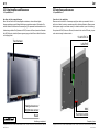
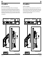
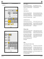
3.3 Schnittstellen und Sensoren
3.31 pureKNX-Base7
Anschluss der Versorgungsleitungen:
Bevor Sie das Gerät in das Unterputzgehäuse einbauen, müssen alle benötigten
Versorgungsleitungen gemäß dieser Abbildung angeschlossen werden. Bitte achten Sie
auf den korrekten Anschluss der Stromversorgung. Der passende Anschlussstecker ist im
Lieferumfang enthalten. Bei Systemen mit PoE (Power-over-Ethernet) muss der Netzwerk-
Hub PoE-fähig sein, damit die Spannungsversorgung mit dem Ethernet-Kabel/-Anschluss
zur Verfügung steht.
Touchscreen
18-48 VDC in
LAN, PoE (optional)
Helligkeitssensor/
Brightness sensor
Reset
KNX
Function button
Abbildung exemplarisch
3.3 Interfaces and sensors
3.31 pureKNX-Base7
Connection to the supply lines
Please connect the device to all necessary supply lines before you assemble it into the
built-in box. Attach the wiring in accordance with the following illustration. Please ensure
that the power supply is connected correctly. A suitable connector is part of the delivery.
For systems with PoE (Power over Ethernet) the network hub must be PoE ready, to pow-
er the device through the ethernet cable.
LAN/PoE
Function button
KNX
18-48 VDC in
Exemplary figure

Ludwig-Rinn-Straße 10-14 • D- 35452 Heuchelheim/Gießen • Phone: +49 6 41-9 62 84-0 • Fax: +49 6 41-9 62 84-28 • www.tci.de Ludwig-Rinn-Straße 10-14 • D- 35452 Heuchelheim/Gießen • Phone: +49 6 41-9 62 84-0 • Fax: +49 6 41-9 62 84-28 • www.tci.de
Seite 24 von 78 Seite 25 von 78
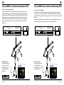
3.32 pureKNX-Line
Anschluss der Versorgungsleitungen
Bevor Sie das Gerät in das Unterputzgehäuse einbauen, müssen alle benötigten
Versorgungsleitungen gemäß dieser Abbildung angeschlossen werden. Bitte achten Sie
auf den korrekten Anschluss der Stromversorgung. Der passende Anschlussstecker ist im
Lieferumfang enthalten. Bei Systemen mit PoE (Power-over-Ethernet) muss der Netzwerk-
Hub PoE-fähig sein, damit die Spannungsversorgung mit dem Ethernet-Kabel/-Anschluss
zur Verfügung steht.
Micro USBReset Helligkeitssensor /
Brightness sensor
Oberseite / Topside
Anschlussfeld / Connectors panel
Front
LED
LAN/PoE
18 - 48
VDC
RP-SMA
Buchse
*
Funktionsknopf/
Function button
KNX
(ohne Funktion /
without function)
Abbildung exemplarisch
3.32 pureKNX-Line
Connection to the supply lines
Please connect the device to all necessary supply lines before you assemble it into the
built-in box. Attach the wiring in accordance with the following illustration. Please ensure
that the power supply is connected correctly. A suitable connector is part of the delivery.
For systems with PoE (Power over Ethernet) the network hub must be PoE ready, to
power the device through the Ethernet cable.
Micro USBReset Helligkeitssensor /
Brightness sensor
Oberseite / Topside
Anschlussfeld / Connectors panel
Front
LED
LAN/PoE
18 - 48
VDC
RP-SMA
Buchse
*
Funktionsknopf/
Function button
KNX
(ohne Funktion /
without function)
Exemplary figure

Ludwig-Rinn-Straße 10-14 • D- 35452 Heuchelheim/Gießen • Phone: +49 6 41-9 62 84-0 • Fax: +49 6 41-9 62 84-28 • www.tci.de Ludwig-Rinn-Straße 10-14 • D- 35452 Heuchelheim/Gießen • Phone: +49 6 41-9 62 84-0 • Fax: +49 6 41-9 62 84-28 • www.tci.de
Seite 26 von 78 Seite 27 von 78
Reset Micro USB (ohne Funktion /
without function)
Helligkeitssensor/
Brightness sensor
Oberseite / Topside Front
LED
LAN, KNX, PoE, Mode A (endspan)
Reset Micro USB (ohne Funktion /
without function)
Helligkeitssensor/
Brightness sensor
Oberseite / Topside Front
LED
LAN, KNX, PoE, Mode A (endspan)
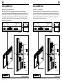
3.33 pureKNX-Line im Konferenztischgehäuse (KTG)
Anschluss der Versorgungsleitung
Das pureKNX-Line10 bietet im Tischgehäuse zur Spannungsversorgung und zum
Anschluß an das Netzwerk bzw. KNX-Bus eine Einkabellösung. Dabei müssen Sie
beachten, dass pureKNX-Line-Systeme mit PoE, pureKNX-Trend-Systeme mit PoE+
betrieben werden und dass der Netzwerk-Hub PoE-fähig sein muss. Wenn Sie die
KNX-Schnittstelle über die Netzwerkdose versorgen beachten Sie die angepasste
Belegung der Netzwerkdose, die nur durch geeignetes Fachpersonal ausgeführt
werden darf.
3.33 pureKNX-Line in a conference table housing (KTG)
Connection to the supply lines
The pureKNX-Line10 with table housing offers a single cable solution for power supply
and connection to the network or KNX bus. Please note that pureKNX-Line systems are
operated with PoE and pureKNX-Trend systems with PoE+. The network hub must be PoE
capable.
If you supply the KNX interface via the network socket, note the adapted assignment of
the network socket, which may be carried out by qualified personnel only.
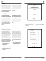
KNX Adapterkabel
Für die Verwendung des
Systems mit ihrer KNX
Installation liegt dem
System der folgende
Adapter bei.
KNX adapter cable
For using the system with
a KNX installation the
following adapter cable is
part of the delivery.

Ludwig-Rinn-Straße 10-14 • D- 35452 Heuchelheim/Gießen • Phone: +49 6 41-9 62 84-0 • Fax: +49 6 41-9 62 84-28 • www.tci.de Ludwig-Rinn-Straße 10-14 • D- 35452 Heuchelheim/Gießen • Phone: +49 6 41-9 62 84-0 • Fax: +49 6 41-9 62 84-28 • www.tci.de
Seite 28 von 78 Seite 29 von 78
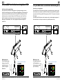
3.34 pureKNX-Trend
Anschluss der Versorgungsleitungen
Bevor Sie das Gerät in das Unterputzgehäuse einbauen, müssen alle benötigten
Versorgungsleitungen gemäß dieser Abbildung angeschlossen werden. Bitte achten Sie
auf den korrekten Anschluss der Stromversorgung. Der passende Anschlussstecker ist im
Lieferumfang enthalten. Bei Systemen mit PoE+ (Power-over-Ethernet) muss der Netz-
werk-Hub PoE+-fähig sein, damit die Spannungsversorgung mit dem Ethernet-Kabel/-
Anschluss zur Verfügung steht.
Abbildung exemplarisch
Reset Mini USB Helligkeitssensor
Oberseite Front
Anschlussfeld
Front
Mikrofon
Leuchtdiode
*optional
USB
AUS1
EIN1
KNX*
LAN/PoE+
24 VDC
RP-SMA
Buchse
Reset *
3.34 pureKNX-Trend
Connection to the supply lines
Please connect the device to all necessary supply lines before you assemble it into the
built-in box. Attach the wiring in accordance with the following illustration. Please ensure
that the power supply is connected correctly. A suitable connector is part of the delivery.
For systems with PoE+ (Power over Ethernet) the network hub must be PoE+ ready, to
power the device through the Ethernet cable.
Exemplary figure
Reset Mini USB Brightness sensor
Topside Front
Connectors panel
Front
MicrophoneLED
*optionally
USB
OUT1
IN1
KNX*
LAN/PoE+
24 VDC
RP-SMA
Connector
Reset *

Ludwig-Rinn-Straße 10-14 • D- 35452 Heuchelheim/Gießen • Phone: +49 6 41-9 62 84-0 • Fax: +49 6 41-9 62 84-28 • www.tci.de Ludwig-Rinn-Straße 10-14 • D- 35452 Heuchelheim/Gießen • Phone: +49 6 41-9 62 84-0 • Fax: +49 6 41-9 62 84-28 • www.tci.de
Seite 30 von 78 Seite 31 von 78
Reset Micro USB Helligkeitssensor/
Brightness sensor
Oberseite / Topside Front
Mikrofon/
Microphone
LED
LAN, KNX, PoE+, Mode A (endspan)
Reset Micro USB Helligkeitssensor/
Brightness sensor
Oberseite / Topside Front
Mikrofon/
Microphone
LED
LAN, KNX, PoE+, Mode A (endspan)
3.35 pureKNX-Trend im Konferenztischgehäuse (KTG)
Anschluss der Versorgungsleitung
Das pureKNX-Trend10 bietet im Tischgehäuse zur Spannungsversorgung und zum
Anschluß an das Netzwerk bzw. den KNX-Bus eine Einkabellösung. Dabei müssen Sie
beachten, dass pureKNX-Line-Systeme mit PoE, pureKNX-Trend-Systeme mit PoE+
betrieben werden und dass der Netzwerk-Hub PoE-fähig sein muss. Wenn Sie die
KNX-Schnittstelle über die Netzwerkdose versorgen beachten Sie die angepasste
Belegung der Netzwerkdose, die nur durch geeignetes Fachpersonal ausgeführt
werden darf.
3.35 pureKNX-Trend in a conference table housing (KTG)
Connection to the supply lines
The pureKNX-Trend10 with table housing offers a single cable solution for power supply
and connection to the network or the KNX bus. Please note that pureKNX-Line systems
are operated with PoE and pureKNX-Trend systems with PoE+. The network hub must be
PoE capable.
If you supply the KNX interface via the network socket, note the adapted assignment of
the network socket, which may be carried out by qualified personnel only.
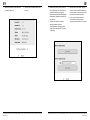
KNX Adapterkabel
Für die Verwendung des
Systems mit ihrer KNX
Installation liegt dem
System der folgende
Adapter bei.
KNX adapter cable
For using the system with
a KNX installation the
following adapter cable is
part of the delivery.

Ludwig-Rinn-Straße 10-14 • D- 35452 Heuchelheim/Gießen • Phone: +49 6 41-9 62 84-0 • Fax: +49 6 41-9 62 84-28 • www.tci.de Ludwig-Rinn-Straße 10-14 • D- 35452 Heuchelheim/Gießen • Phone: +49 6 41-9 62 84-0 • Fax: +49 6 41-9 62 84-28 • www.tci.de
Seite 32 von 78 Seite 33 von 78
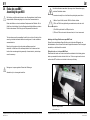
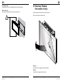
3.4 Einbau des pureKNX /
Assembling the pureKNX
!Die Anleitung zum Einbau des Unterputz- oder Einputzgehäuses finden Sie dem
entsprechenden Gehäuse beigelegt und im Internet auf www.ambiento.de.
Einbau des Gerätes nur durch autorisiertes Fachpersonal und Elektriker. Die tci
GmbH kann keine Haftung für bei der Montage beschädigte Gehäuse und deren
Funktion übernehmen. Eine Prüfung durch Fachpersonal ist erforderlich.
The instruction manual for assembling the built in box or the built in box for flush
mounting is included with each delivered mounting frame. It is also available on
www.ambiento.de.
Mounting of the system only by authorized qualified personnel and
electrician. tci GmbH can not be held responsible for built-in boxes and their
function that were damaged during assembly. An examination by technical per-
sonnel is necessary.
Montage nur im spannungsfreien Zustand der Zuleitungen.
Assemble only in a de-energized condition.
Das Gerät sollte bei einwandfreier Spannungs- bzw. Netzwerkversorgung
nach dem Einschalten starten.
If connected correctly the unit will start after pushing the power button.
!
1) Bei der Option WLAN, wird die USB-Port-Funktion limitiert
2) DCIn und PoE können gleichzeitig verwendet werden, wird aber nicht
empfohlen.
1) The WLAN option limits the USB port function
2) DCIn and PoE can be used at the same time, but it is not recommend.
mitgelieferter Klapp-Ferritkern
included ferrite core
Anbringen des Klapp-Ferritkerns am pureKNX-Trend
Bringen Sie den mitgelieferten Klapp-Ferritkern wie im folgenden Bild gezeigt, am
Netzwerkkabel an, bevor Sie das Gerät in das Putzgehäuse einsetzen. Dies ist zwingend
erforderlich, um die Klasse B zu erreichen!
Fitting the ferrit core to the pureKNX-Trend
Please attach the ferrite core to the network cable as indicated in the following picture
before you assemble the device into the built-in box. This is an urgent need in order to
achieve class B! The ferrite core is included in the scope of delivery.

Ludwig-Rinn-Straße 10-14 • D- 35452 Heuchelheim/Gießen • Phone: +49 6 41-9 62 84-0 • Fax: +49 6 41-9 62 84-28 • www.tci.de Ludwig-Rinn-Straße 10-14 • D- 35452 Heuchelheim/Gießen • Phone: +49 6 41-9 62 84-0 • Fax: +49 6 41-9 62 84-28 • www.tci.de
Seite 34 von 78 Seite 35 von 78
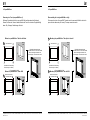
3.41 pureKNX-Base
Demontage der Front (nur pureKNX-Base!):
Entfernen Sie zunächst die Front vom pureKNX: Sie benötigen dazu kein Werkzeug!
Fassen Sie Oben und Unten mit beiden Händen die Front an und ziehen Sie gleichmäßig
daran. Die „Schnapp“-Verbindungen löst sich.
Einbau des pureKNX-Base7 direkt in die Wand
Einbau des pureKNX-Base7 in das UPG
Montage
Mounting Schrauben im Lieferumfang
Screws are part of delivery
Bei beiden Montagevarianten
steht das Gerät ca. 5 mm vor der Wand!
At both mounting variants the unit
stands approx. 5 mm before the wall!
Wand
Wall
176 mm
130 mm
1. Ausschnitt/Cutout
ohne Unterputzgehäuse
without built-in box
3. Einbau pureKNX direkt in die Wand/
Mounting pureKNX directly into the wall
Diese Löcher nutzen!
Use these holes!
2. Reinigen Sie den den Ausschnitt
Clean the mounting hole
Wand
Wall
Wand
Wall
181 mm
136 mm
1. Ausschnitt/Cutout
mit Unterputzgehäuse
with built-in box
2. Einbau UPG/Mounting UPG
Wand
Wall
UPG
UPG-Öffnung muss mit
fertiger Wand abschließen!
UPG opening must be end
with the surface of the wall!
3. Einbau pureKNX in UPG/
Mounting pureKNX into UPG
Wand
Wall
Diese Löcher nutzen!
Use these holes!
A
B
Mounting the pureKNX-Base7 directly into the wall
Mounting the pureKNX-Base7 into its UPG
3.41 pureKNX-Base
Disassembling the front (pureKNX-Base only!):
First remove the front of the pureKNX: Therefore no tools are needed! Hold the front at its
top and bottom sides and pull it evenly. The snap connections solve.
Montage
Mounting Schrauben im Lieferumfang
Screws are part of delivery
Bei beiden Montagevarianten
steht das Gerät ca. 5 mm vor der Wand!
At both mounting variants the unit
stands approx. 5 mm before the wall!
Wand
Wall
176 mm
130 mm
1. Ausschnitt/Cutout
ohne Unterputzgehäuse
without built-in box
3. Einbau pureKNX direkt in die Wand/
Mounting pureKNX directly into the wall
Diese Löcher nutzen!
Use these holes!
2. Reinigen Sie den den Ausschnitt
Clean the mounting hole
Wand
Wall
Wand
Wall
181 mm
136 mm
1. Ausschnitt/Cutout
mit Unterputzgehäuse
with built-in box
2. Einbau UPG/Mounting UPG
Wand
Wall
UPG
UPG-Öffnung muss mit
fertiger Wand abschließen!
UPG opening must be end
with the surface of the wall!
3. Einbau pureKNX in UPG/
Mounting pureKNX into UPG
Wand
Wall
Diese Löcher nutzen!
Use these holes!
A
B

Ludwig-Rinn-Straße 10-14 • D- 35452 Heuchelheim/Gießen • Phone: +49 6 41-9 62 84-0 • Fax: +49 6 41-9 62 84-28 • www.tci.de Ludwig-Rinn-Straße 10-14 • D- 35452 Heuchelheim/Gießen • Phone: +49 6 41-9 62 84-0 • Fax: +49 6 41-9 62 84-28 • www.tci.de
Seite 36 von 78 Seite 37 von 78
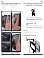
Schritt (5) entfällt bei Montage des Gerätes
in das UPG
Step (5) is omitted if the device is assem-
bled in the UPG
)* Abb. pureKNX-Trend7. Andere Systeme mit ähnlicher
Mechanik!
)* fig. pureKNX-Trend7. Other models with similiar
action!
*
*
1
3
4
2
5
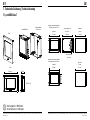
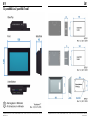
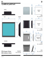
3.42 Einbau des pureKNX-Line & pureKNX-Trend in das UPG oder EPG
Mounting the pureKNX-Line & pureKNX-Trend into its UPG or EPG
Für alle Geräte gilt:
Lüftungschlitze an Ober- und Unterseite dürfen nicht verdeckt werden!
Valid for all devices:
Don’t cover the ventilation slots at the top and bottom side!
Wand/Wall
!
Richtig!
OK!
Falsch!
Not OK!
Wand
Wall
Wand
Wall
Wand/Wall
UPG
Wandausschnitt
Mounting hole
Von der Innenseite verschrauben.
Bolt down from the inside.
!
Unterputz-
gehäuse
built-in box
!
1. & 2. Setzen Sie das Gerät auf die 4
Montagelaschen des Rahmens
Please put the device on the 4
mounting brackets of the installation
frame
3. & 4. Halten Sie das Gerät sicher in Posi-
tion und ziehen Sie die 4 Schrauben
mit beigelegtem Inbusschlüssel fest
(Die Schrauben sollten sich im
Auslieferungszustand des Gerä-
tes bereits in den Schraublöchern
befinden)
Reliably hold the device in position
and tighten the 4 screws with the
Allen key, which is part of the delivery
(In delivery state the screws can be
found in the device‘s screw holes
already)
5. Drücken Sie das Gerät sanft in den
Rahmen bis es merklich einrastet
Now gently push the device into the
installation frame until it locks in place
EPG
mura16W-GT
31.05.2013
Rev. 1.0
Unten/Bottom
Front
387mm
369mm
9mm 9mm
23mm
74mm
242mm
Seite/Side
224mm 9mm
9mm
UPG
mura16W-GT
31.05.2013
Rev. 1.0
Unten/Bottom
Front Seite/Side
378mm
233mm
225mm
370mm
225mm
71mm
64mm
233mm
Wand/Wall
!
Richtig!
OK!
Falsch!
Not OK!
Wand
Wall
Wand
Wall
Wand/Wall
UPG
Wandausschnitt
Mounting hole
Von der Innenseite verschrauben.
Bolt down from the inside.
!
Unterputz-
gehäuse
built-in box
!

Ludwig-Rinn-Straße 10-14 • D- 35452 Heuchelheim/Gießen • Phone: +49 6 41-9 62 84-0 • Fax: +49 6 41-9 62 84-28 • www.tci.de Ludwig-Rinn-Straße 10-14 • D- 35452 Heuchelheim/Gießen • Phone: +49 6 41-9 62 84-0 • Fax: +49 6 41-9 62 84-28 • www.tci.de
Seite 38 von 78 Seite 39 von 78
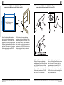
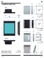
116mm
140mm
Wand-Bohrschablone /
wall drilling jig
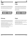
3.43 Montage des pureKNX-Line & pureKNX-Trend im APG
Mounting the pureKNX-Line & pureKNX-Trend in the APG
Bringen Sie mittels der Bohrschablone
die Löcher für die Schraubbesfestigung
des Gehäuses an. Führen Sie die Versor-
gungsleitungen durch die Aussparung des
Gehäuses. Befestigen Sie das Gehäuse an
der Wand. Die Montage in das iluna/aluna
Gehäuse erfolgt analog zum EPG/UPG,
wie unter Punkt 3.42 beschrieben.
Drill the holes for the screw attachment
under the aid of the wall drilling jig. Put the
cables through the hole in the case. Attach
the housing on the wall. The assembly into
the housing of the iluna/aluna is carried out
analogous to the EPG/UPG (built-in box for
flush mounting/built-in box), as described
earlier in 3.42.
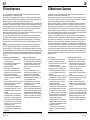
3.44 Montage des pureKNX-Line & pureKNX-Trend im KTG
Mounting the pureKNX-Line & pureKNX-Trend in the KTG
(I) Schrauben Sie die Standfüße an das
Gehäuse. (II) Bringen Sie die beiden
selbstklebenden Gummifüße am Gehäuse
an. (III) Schließen Sie hier, wie in Kapitel
3.33 & 3.35 beschrieben die Versorgungs-
leitung an. Die Montage in das iluna/aluna
Gehäuse erfolgt analog zum EPG/UPG,
wie unter Punkt 3.42 beschrieben.
(I) Assemble the supporting feet to the
housing. (II) Attach the self-adhesive rubber
feet to the case. (III) Connect supply lines
as per description in chapter 3.33 & 3.35
The assembly into the housing of the iluna/
aluna is carried out analogous to the EPG/
UPG (built-in box for flush mounting/built-in
box), as described in 3.42.
Seite wird geladen ...
Seite wird geladen ...
Seite wird geladen ...
Seite wird geladen ...
Seite wird geladen ...
Seite wird geladen ...
Seite wird geladen ...
Seite wird geladen ...
Seite wird geladen ...
Seite wird geladen ...
Seite wird geladen ...
Seite wird geladen ...
Seite wird geladen ...
Seite wird geladen ...
Seite wird geladen ...
Seite wird geladen ...
Seite wird geladen ...
Seite wird geladen ...
Seite wird geladen ...
Seite wird geladen ...
-
 1
1
-
 2
2
-
 3
3
-
 4
4
-
 5
5
-
 6
6
-
 7
7
-
 8
8
-
 9
9
-
 10
10
-
 11
11
-
 12
12
-
 13
13
-
 14
14
-
 15
15
-
 16
16
-
 17
17
-
 18
18
-
 19
19
-
 20
20
-
 21
21
-
 22
22
-
 23
23
-
 24
24
-
 25
25
-
 26
26
-
 27
27
-
 28
28
-
 29
29
-
 30
30
-
 31
31
-
 32
32
-
 33
33
-
 34
34
-
 35
35
-
 36
36
-
 37
37
-
 38
38
-
 39
39
-
 40
40


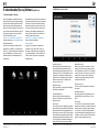
TCi pureKNX-Serie Bedienungsanleitung
- Typ
- Bedienungsanleitung
- Dieses Handbuch eignet sich auch für
in anderen Sprachen
- English: TCi pureKNX-Serie Owner's manual
Verwandte Artikel
-
 TCi amena7-XS Bedienungsanleitung
-
 TCi pureKNX Bedienungsanleitung
-
 TCi luna Bedienungsanleitung
-
 TCi pureKNX4hotel Bedienungsanleitung
-
 TCi contatto_FlatClient-VI Bedienungsanleitung
-
 TCi IPC-S2 Bedienungsanleitung
-
 TCi IPC-TB-PREM Bedienungsanleitung
-
 TCi H-ST-Series Bedienungsanleitung
-
 TCi G07T Bedienungsanleitung
-
 TCi solo Bedienungsanleitung


