Wita Thermostatisches Mischventil D-GB-PL-ES Bedienungsanleitung
- Typ
- Bedienungsanleitung

1. Anwendungsbereich
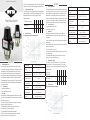
Die aus Messing hergestellten Thermischen Ventile, werden
bevorzugt für Fußbodenheizungssysteme eingesetzt, um z.B. bei
Heizungsanlagen den Fußbodenaufbau vor hohen Tempera-
turen zu schützen. Die Temperatur des gemischten Wassers,
wird durch ein Dehnstoelement angetriebenes Ventil geregelt.
In der Trinkwasserinstallation, kann das Thermische Ventil als
Verbrühungsschutz eingesetzt werden. Die Thermischen Ventile
können mit Außengewinde, Überwurfmutter und Pumpenflan-
sche geliefert werden.
1.1 Lieferumfang
• Original Montageanleitung
• Thermostatisches Mischventil
2. Montage
Alle Installations- und Wartungsarbeiten dürfen nur von qualifi-
ziertem Personal durchgeführt werden und müssen den örtlichen
Vorschriften entsprechen.
1. Sperren Sie die Wasserzufuhr ab und reinigen Sie die Rohrlei-
tung, in die das Ventil eingebaut ist.
2. Es wird empfohlen, Absperrventile an den Wasserein-
und -auslässen des Ventils zu verwenden.
3. Gegebenenfalls Rückschlagventile verwenden
4. Stellen Sie die Mischwassertemperatur durch Drehen der
Kappe ein. Beachten Sie die folgende Tabelle
5. Die Temperatureinstellung des Ventils sollte jährlich überprüft
werden, um die normale Funktionsfähigkeit zu gewährleisten.
3. Temperatureinstellung
Diese Tabelle gibt einen ungefähren Wert an. Die tatsächliche
Temperatur hängt von den Betriebsbedingungen ab. Die Vor-
lauftemperatur kann stufenlos nach folgender Tabelle
eingestellt werden:
Temperatureinstellung
Temperatur °C
4. Technische Daten
4.1 Durchfluss- und Druckverlustdiagramm
1. Field of application
The thermal valves made of brass are preferably used for under-
floor heating systems, e.g. to protect the floor structure against
high temperatures in heating systems. The temperature of the
mixed water is controlled by a valve driven by an expansion
element. In drinking water installations, the thermal valve can be
used for protection against scalding. The thermal valve can be
supplied with a male thread, a union nut and a pump flange.
1.1 Scope of delivery
- original installation instructions
- thermostatic mixing valve
2. Installation
All installation and maintenance work must be carried only
by qualified personnel only and must comply with the local
regulations.
1. Shut o the water supply and clean the pipework in which the
valve is fitted.
2. It is recommended to install shut-o valves at the water inlet
and outlet of the valve.
3. Use check valves if necessary
4. Set the mixed water temperature by turning the cap. Observe
the following table
5. The temperature setting of the valve should be checked
annually to ensure normal functioning.
3. Temperature setting
This table gives an approximate value. The actual tempe-
rature depends on the operating conditions. The supply
temperature can be continuously adjusted according to the
following table:
4. Technical data
4.1 Flow and pressure drop diagram
Thermostatisches Mischventil
Thermostatic mixing valve
NUR ORIGINAL MIT DER RAUTE®
Deutsch
Artikelnummer: M 70 110 / M 70 100
Kvs-Wert: 3,2
Temperaturbereich: 20 – 50 ° C / 37 – 60 °C
Max. Betriebsdruck: 10 bar
Max. Temperatur: 100 °C
Dierenzdruck: 3 bar ( 0,3 MPa )
Regelgenauigkeit: +/- 2°C bei 2l/min
Material: Messing vernickelt
English
temperature
adjustment
temperature °C
Article number: M 70 110 / M 70 100
Kvs value: 3,2
Temperature range: 20 – 50 ° C / 37 – 60 °C
Max. Operating
pressure:
10 bar
Max. Temperature: 100 °C
Dierential pressure: 3 bar ( 0,3 MPa )
Control accuracy: +/- 2°C bei 2l/min
Material: brass nickel plated
Pressure drop P (k Pa)
Flow m³/h
Kvs
(m³/h)

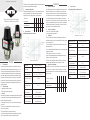
1. Zastosowanie
Zawory termostatyczne wykonane z mosiądzu stosowane są
głównie w instalacjach ogrzewania podłogowego, np. w celu
ochrony konstrukcji podłogi przed wpływem wysokich tem-
peratur. Temperatura wody zmieszanej jest regulowana przez
zawór napędzany elementem rozprężnym. W instalacji wody
pitnej zawór termostatyczny może służyć jako ochrona przed
poparzeniem. Zawory termostatyczne mogą być dostarczone
wraz z gwinten zewnętrznym, nakrętką łączącą i kołnierzem
przyłączeniowym.
1.1 Zakres dostawy
• Oryginalna instrukcja montażu
• Termostatyczny zawór mieszający
2. Montaż
Wszystkie prace związane z montażem lub konserwacją produk-
tu muszą być wykonywane przez wykwalifikowany personel i
zgodnie z lokalnymi przepisami.
1. Odetnij dopływ wody i oczyść rurę, w której zamontowany
jest zawór.
2. Zaleca się stosowanie zaworów odcinających na wlocie i
wylocie wody z zaworu.
3. W razie potrzeby użyj zaworów zwrotnych.
4. Ustaw temperaturę wody zmieszanej przekręcając pokrywę.
Zwróć uwagę na wartości podane w załączonej tabeli.
5. Raz do roku należy sprawdzić ustawienia temperatury zaworu,
aby zapewnić jego prawidłowe działanie.
3. Ustawienie temperatury
Tabela podaje przybliżone wartości. Temperatura rzeczywista
zależy od warunków pracy. Temperaturę zasilania można
regulować w sposób ciągły, zgodnie z poniższą tabelą:
ustawienie
temperatury
temperatura w °C
4. Dane techniczne
4.1 Wykres przepływu i strat ciśnienia
1. Campo de aplicación
Las válvulas térmicas de latón se utilizan preferentemente para
sistemas de calefacción por suelo radiante, por ejemplo, para
proteger la estructura del suelo contra las altas temperaturas en
los sistemas de calefacción. La temperatura del agua mezclada
se controla mediante una válvula accionada por un elemento
de expansión. En las instalaciones de agua potable, la válvula tér-
mica se puede utilizar para la protección contra las quemaduras.
La válvula térmica pueden ser entregado con una rosca macho,
una tuerca de unión y una brida de bomba.
1.1 Alcance de la entrega
- instrucciones de instalación originales
- válvula mezcladora termostática
2. Instalación
Todos los trabajos de instalación y mantenimiento deben ser
realizados únicamente por personal cualificado y deben cumplir
con la normativa local.
1. Corte el suministro de agua y limpie la tubería en la que está
instalada la válvula.
2. Se recomienda instalar válvulas de cierre en la entrada y salida
de agua de la válvula.
3. Utilice válvulas de retención si es necesario
4. Ajuste la temperatura del agua mezclada girando el tapón.
Tenga en cuenta la siguiente tabla
5. El ajuste de la temperatura de la válvula debe comprobarse
anualmente para garantizar un funcionamiento normal.
3. Ajuste de la temperatura
Esta tabla ofrece un valor aproximado. La temperatura real
depende de las condiciones de funcionamiento. La tempe-
ratura de alimentación ser ajustada continuamente según la
siguiente tabla:
4. Datos técnicos
4.1 Diagrama de flujo y caída de presión
Termostatyczny zawór mieszający
Válvula mezcladora termostática
NUR ORIGINAL MIT DER RAUTE®
Polski
Nr artykułu: M 70 110 / M 70 100
Wartość Kvs: 3,2
Zakres temperatur: 20 – 50 ° C / 37 – 60 °C
Maksymalne ciśnienie
robocze:
10 bar
Maksymalna tempe-
ratura:
100 °C
Różnica ciśnień: 3 bar ( 0,3 MPa )
Precyzyjność regulacji: +/- 2°C bei 2l/min
Materiał wykonania mosiądz niklowany
Español
Ajuste de la tempe-
ratura
temperatura °C
Número de artículo: M 70 110 / M 70 100
Valor Kvs: 3,2
Rango de tempera-
tura:
20 – 50 ° C / 37 – 60 °C
Máx. Presión de funci-
onamiento:
10 bar
Máx. Temperatura: 100 °C
Presión diferencial: 3 bar ( 0,3 MPa )
Precisión de control: +/- 2°C bei 2l/min
Material: latón niquelado
Caída de presión P (k Pa)
Flujo m³/h
Kvs
(m³/h)
spadek ciśnienia P (k Pa)
przepływ
m³/hKvs
(m³/h)
-
 1
1
-
 2
2


Wita Thermostatisches Mischventil D-GB-PL-ES Bedienungsanleitung
- Typ
- Bedienungsanleitung
in anderen Sprachen
Andere Dokumente
-
Honeywell HF 49 Bedienungsanleitung
-
 Purmo Euro Pump Unit Bedienungsanleitung
-
Danfoss DWH Installationsanleitung
-
resideo Braukmann TS131 Installationsanleitung
-
Trane FCAS Technical Manual
-
-
-
STIEBEL ELTRON WPSF Operation Instruction
-
-
