
FMSMODEL.COM
80mm
Dassault Rafale
Manuel d’utilisation
Instruction Manual
Bedienungsanleitung
操作手册
REALISTIC STABLERIGID
Retract & Flaps Installed Strong durable EPO Smooth flying performance


WARNING: Read the ENTIRE instruction manual to become familiar with the features of the product before operating.
Failure to operate the product correctly can result in damage to the product,personal property and cause serious injury.
This is a sophisticated hobby product and NOT a toy. It must be operated with caution and common sense and failure to do so
could result in injury or damage to the product or other property. This product is not intended for use by children without direct
adult supervision.
This manual contains instructions for safety operation and maintenance. It is essential to read and follow all the instructions and
warnings in the manual prior to assembly, setup or use, in order to operate and avoid damage or serious injury.
WARNING
As the user of this product, you are solely responsible for operating in a manner that does not endanger yourself and others or
result in damage to the product or the property of others. This model is controlled by a radio signal subject to interference from
many sources outside your control. This interference can cause momentary loss of control so it is advisable to always keep a
safe distance in all directions around your model, as this margin will help avoid collisions or injury.
Age Recommendation: Not for children under 14 years. This is not a toy.
·Never operate your model with low transmitter batteries.
·Always operate your model in an open area away from cars, traffic or people.
·Avoid operating your model in the street where injury or damage can occur.
·Never operate the model in populated areas for any reason.
·Carefully follow the directions and warnings for this and any optional support equipment you use (chargers,rechargeable
battery packs, etc.)
·Keep all chemicals, small parts and anything electrical out of the reach of children.
·Moisture causes damage to electronics. Avoid water exposure to all equipment not specifically designed and protected for this
purpose.
·Never lick or any place of any your model in your mouth as it could cause serious injury or even death.
Lithium Polymer (Li-Po) Battery Warning
CAUTION: Always follow the manufacturer’s instructions for safe use and disposal of batteries. Fire, property
damage, or serious injury can result from the mishandling of Li-Po batteries.
By handling, charging or using a Li-Po Battery you assume all risks associated with lithium batteries.
If at any time the batteries begin to swell or balloon, discontinue use immediately!
Always store the batteries at room temperature in a dry area to extend the life of the battery. Always transport
or temporarily store the battery in a temperature range of 40-120F. Do not store the battery or model in a car or in direct sunlight.
If stored in a hot car, the battery can be damaged or even catch fire.
Never use a Ni-Mh Charger to charge Li-Po Batteries. Failure to charge the battery with a Li-Po compatible charger
may cause fire resulting in personal injury and property damage.
Never discharge Li-Po Cells below 3V.
Never leave charging batteries unattended.
Never charge damaged batteries.
Charging the Flight Battery Warning
Use a battery charger that is designed to safely charge the Li-Po Battery. Read the charger instructions care
fully before use. When charging the battery, make certain the battery is on a heat resistant surface. It is also highly
recommended to place the Li-Po Battery inside a fire resistant charging bag readily available at hobby shops or
online.
p w
2

3
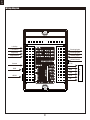
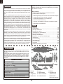
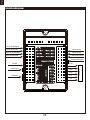
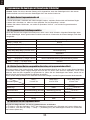
Before assembly, please inspect the contents of the kit. The
photo below details the contents of the kit with labels. If any
parts are missing or defective, please identify the name or
part number (refer to the spare parts list near the end of the
manual) then contact your local shop or email us: support
Kit contents
Introduction
Kit contents
Model assembly
Battery installation
Receiver diagram
Get your model ready to fly
Clevis installation
Control horn and servo arm settings
Center of gravity(CG)
Before flying the model
Flying course
Troubleshooting
Spare parts list content
User Manual of Brushless Speed Controller
3
3
4
10
10
10
12
12
12
13
13
14
14
15
..............................................................
..............................................................
........................................................
.....................................................
......................................................
.........................................
......................................................
..............................
.................................................
...............................................
............................................................
........................................................
...............................................
....................
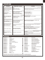
Table of contents
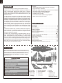
Introduction
Wingspan: 974mm /38.3 in
Overall Length: 1409mm /55.5 in
Flying Weight: Around 3280g
Motor Size: 3280 KV2100
Wing Load: 85.2g/dm² (0.17oz/in²)
Wing Area: 38.5dm² (596.6 sq.in)
ESC: 100A
Servo: 13g X 7pcs,9g X 2pcs
Recommended Battery: 22.2V4000mAh-5000mAh 45c
Specifications
@fmsmodel.com
2 years in the making, introducing the FMS 80mm Rafale
Designed by the French Dassault company, the Rafale is a
highly maneuverable delta-winged fighter with a full-flying
canard. The excellent dogfighting, carrier operations and air to
surface attack performance of the Rafale has allowed it to gain
worldwide sucess.
Like its full-scale counterpart, the FMS 80mm Rafale features
an attractive trim scheme, excellent scale details and fully
functional canards- allowing the aircraft to be truly unique when
compared to other 80mm EDF aircraft on the market today.
Developed to replicate both the looks and performance of the
real aircraft, FMS has dedicated it's decades long experience
into designing the 80mm Rafale. Details such as the pilot,
cockpit interior, panels, removable armaments, auxiliary fuel
tanks, refueling probe, targeting sensor etc; dynamic features
such as functional LED navigation and landing lights, CNC
shock-absorbing electric retracts, functional canards and flaps
etc.
Like all other FMS aircraft, the 80mm Rafale was designed to
reduce build time to a minimum. Utilising screws, latches and
quick connectors, experienced builders can complete the build
process in as little as 5 minutes.
Functions such as delta-mixing, sequential landing gear bay
doors, alternating flash navigation lights, nose gear landing
lights, slowed flaps etc are all controlled by a central control
board. An 80mm 12 bladed EDF with a platinum edition 3280
inrunner motor and 100A high performance ESC easily accom-
plishes fighter jets maneuvers with realistic sound and speed.
Don't miss out on your chance to own one of the best looking
modern fighters- the FMS 80mm Rafale!
Features
• 3280-2100KV platinum edition inrunner motor with a
high-performance 100A ESC
• Delta wing design with full flying canards and functional flaps
• CNC metal shock-absorbing landing gear
• Functional navigation and landing lights
• Central function controller
• Functional and static details lovingly replicated
• Water based vibrant trim scheme
A. B.
C.
F. G. H.
I. J.
D.
E.
A:
B:
C:
D:
Fuselage
Nose cone
Main wing
Weapons
package
E:
F:
G:
H:
Auxiliary fuel tanks
Vertical stabilizer
Wing spar
Fuel probe
I:
J:
Canard
Screw set
HKM3.0x16*4
HKM3.0x20*2
4x3mm set screw*2

4
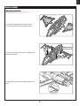
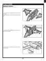
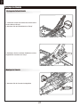
Model assembly
HKM3.0*16mm
Main wing installation
1.Connect the wing halves onto the wing spar.
2.Fit the wing halves into the fuselage cutouts.
3.Secure the wing halves onto the fuselage with
the included screws.
4.Adjust the elevon surfaces to align with the fuse-
lage.

5
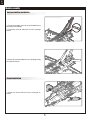
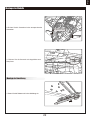
Model assembly
Vertical stabilizer installation
1.Connect the rudder servo to the preinstalled servo
lead within the fuselage.
2. Install the vertical stabilizer into the fuselage
pocket.
HKM3.0*20mm
Canard installation
3.Attach the vertical stabilizer to the fuselage using
the included screws.
1.Install the canard halves into the fuselage as
shown.

6
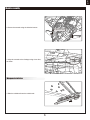
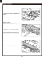
Model assembly
2.Secure the canards using the included screws.
3. Align the canards to the fuselage using a hex drive,
as shown.
Weapons installation
1.Slide the missiles aft onto the missile rack.
4*3mm
set screw

7
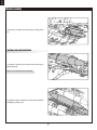
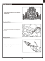
Model assembly
2.Attach the missiles onto the wings by sliding them
aft.
Auxiliary fuel tank installation
1.Install the auxiliary fuel tanks onto the wings by
sliding them aft.
Note: the sticker side faces outboard.
2.Install the center auxiliary fuel tank onto the bottom
fuselage by sliding it aft.

8
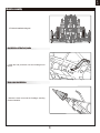
Model assembly
3.Finished installation diagram.
Installation of the fuel probe
1.Slide the fuel probe aft onto the fuselage until
secure.
Nose cone installation
1.Attach the nose cone onto the fuselage, ensuring
correct orientation.

9
Wiring diagram
Left flap
Flashing lights
Receiver
Flashing lights
landing lights
GEAR DOOR
FLAP
GEAR
RUD
THR
ELE
AIL
Left aileron
Right flap
Right aileron
Canard
RUD
GEAR

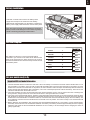
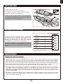
Important ESC and model information
The ESC included with the model has a safe start. If the motor battery is connected to the ESC and the throttle stick is not in
the low throttle or off position, the motor will not start until the throttle stick is moved to the low throttle or off position. Once the
throttle stick is moved to the low throttle or off position, the motor will emit a series of beeps. Several beeps with the same tune
means the ESC has detected the cells of the battery. The count of the beeps equals the cells of the battery. The motor is now
armed and will start when the throttle is moved.
The motor and ESC come pre-connected and the motor rotation should be correct. If for any reason the motor is rotating in the
wrong direction, simply reverse two of the three motor wires to change the direction of rotation.
The motor has an optional brake setting. The ESC comes with brake switched off and we recommend that the model be flown
with the brake off. However, the brake could be accidentally switched on if the motor battery is connected to the ESC while the
throttle stick is set at full throttle. To switch the brake off, move the throttle stick to full throttle and plug in the motor battery. The
motor will beep one time. Move the throttle stick to low throttle or the off position. The motor is ready to run and the brake will
be switched off.
Battery Selection and Installation. We recommend the 22.2V4000mAh-5000mAh 45c Li-Po battery. If using another battery,
the battery must be at least a 22.2V4000mAh-5000mAh 45c battery. Your battery should be approximately the same capacity,
dimension and weight as the 22.2V4000mAh-5000mAh 45c Li-Po battery to fit the fuselage without changing the center of
gravity significantly.
1.
2.
3.
4.
10
1.Pull back on the latch and remove the battery hatch.
2.Apply the hook tape to the cable end of the battery.
3.Slide the full charged battery into the battery compartment
with the power supply cable toward the rear end of the plane.
Note: The center of gravity can be adjusted by moving the
battery forward or aft.Having the correct center of gravity is
critical to achieving proper flight characteristics.
Battery installation
Receiver diagram
Get your model ready to fly
The cables from the servo connector board should be
connected to your receiver in the order shown. Note that the
LEDs can be powered by any spare channel on the receiver.
Tuck the wire leads into the recessed cavity towards the rear
of the battery hatch.
Spare
Gear
Rudder
Throttle
EIevator
Aileron
Channel-1
Aile
Channel-2
Elev
Channel-3
Thro
Channel-4
Rudd
Channel-5
Gear
Channel-6
Spare
6
5
4
3
2
1

Transmitter and model setup
Before getting started, bind your receiver with your transmitter.
Please refer to your transmitter manual for proper operation.
CAUTION: To prevent personal injury, DO NOT install the propel-
ler assembly onto the motor shaft while testing the control surfac-
es. DO NOT arm the ESC and do not turn on the transmitter until
the Transmitter Manual instructs you to do so.
Tips: Make sure all control sticks on your radio are in the neutral
position (rudder, elevator, ailerons) and the throttle is in the OFF
position. Make sure both ailerons move up and down (travel) the
same amount. This model tracks well when the left and right
ailerons travel the same amount in response to the control stick.
Move the controls on the transmitter to make sure the aircraft
control surface moves correctly. See diagrams right.
11
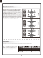
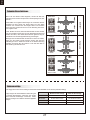
Control throws
The suggested control throw setting for the 80mm Dassault Rafale are as follows (dual rate setting):
Tips: On the first flight, fly the model in low rate.
The first time you use high rates,be sure to fly at
low to medium speeds. High rate, as listed, is
only for EXTREME maneuvering.
Aileron
Bank left
Bank right
Elevator
Climb
Descend
Steering Rudder
Steer left
Steer right
20mm up / dowm 12mm up / dowm
12mm up / dowm
20mm left / right
20mm up / dowm
8mm up / dowm
12mm up / dowm
24mm left / right
canard

12
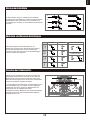
More control throw
Less control throw
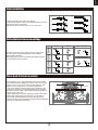
Horns Arms
Clevis installation
a.
b.
c.
d.
e.
f.
1.Pull the tube from the clevis to the linkage.
2.Carefully spread the clevis, then insert the clevis pin into the
desired hole in the control horn.
3.Move the tube to hold the clevis on the control horn.
Control horn and servo arm settings
The table shows the factory settings for the control horns
and servo arms. Fly the aircraft at the factory settings
before making changes.
After flying,you may choose to adjust the linkage positions
for the desired control response.
ElevatorRudderAileronsCanard
Check the C.G. (Center of gravity)
When balancing your model, adjust the battery as necessary
so the model is level or slightly nose down. This is the correct
balance point for your model. After the first flight, the CG
position can be adjusted for your personal preference.
1. The recommended Center of Gravity (CG) location for your
model is(110-130mm) from the leading edge of the main wing
(as shown) with the battery pack installed. Mark the location of
the CG on top of the wing.
2. When balancing your model, support the plane at the marks
made on the bottom of the main wing with your fingers or a
commercially available balancing stand. This is the correct
balance point for your model. Make sure the model is assembled
and ready for flight before balancing.
NN

13
Take off
Maintenance
Landing
Find a suitable flying site
Perform the range check for your plane
Monitor your flight time
Find a flying site clear of buildings, trees, power lines and
other obstructions. Until you know how much area will be
required and have mastered flying your plane in confined
spaces, choose a site which is at least the size of two to three
football fields - a flying field specifically for R/C planes is best.
Never fly near people - especially children, who can wander
unpredictably.
As a precaution, an operational ground range test should be
performed before the first flight each time you go out.
Performing a range test is a good way to detect problems
that could cause loss of control such as low batteries, defective
or damaged radio components, or radio interference. This
usually requires an assistant and should be done at the actual
flying site you will be using.
First turn on the transmitter, then install a fully-charged battery
into the fuselage. Connect the battery and install the hatch.
Remember, use care not to bump the throttle stick. Otherwise,
the propeller/fan will turn and possibly cause damage or injury.
Note: Please refer to your Transmitter Manual that came with
your radio control system to perform a ground range check. If
the controls are not working correctly or if anything seems
wrong, do not fly the model until you correct the problem. Make
certain all the servo wires are securely connected to the
receiver and the transmitter batteries have a good connection.
Monitor and limit your flight time using a timer (such as on a
wristwatch or in your transmitter if available). When the
batteries are getting low you will usually notice a performance
drop before the ESC cuts off motor power, so when the plane
starts flying slower you should land. Often (but not always)
power can be briefly restored after the motor cuts off by
holding the throttle stick all the way down for a few seconds.
To avoid an unexpected dead-stick landing on your first flight,
set your timer to a conservative 4 minutes. When your alarm
sounds you should land right away.
Before flying the model
Flying course
While applying power, slowly steer to keep the model straight.
The model should accelerate quickly. As the model gains flight
speed you will want to climb at a steady and even rate. It will
climb out at a nice angle of attack (AOA).
Flying
Always choose a wide-open space for flying your plane. It is
ideal for you to fly at a sanctioned flying field. If you are not
flying at an approved site always avoid flying near houses,
trees, wires and buildings. You should also be careful to avoid
flying in areas where there are many people, such as busy
parks, schoolyards, or soccer fields. Consult laws and
ordinances before choosing a location to fly your aircraft. After
takeoff, gain some altitude. Climb to a safe height before trying
technical manoeuvres, including high speed passes, inverted
flight, loops, and point rolls.
Land the model when you hear the motor pulsing (LVC) or if
you notice a reduction in power. If using a transmitter with a
timer, set the timer so you have enough flight time to make
several landing approaches.
The model’s three point landing gear allows the model to land
on hard surfaces. Align model directly into the wind and fly
down to the ground. Fly the airplane down to the ground using
1/4-1/3 throttle to keep enough energy for proper flare. Before
the model touches down, always fully decrease the throttle to
avoid damaging the propeller or other components. The key to
a great landing is to manage the power and elevator all the
way to the ground and set down lightly on the main landing
gear. After a few flights you will find the model can be set down
lightlyon the mains and you can hold the nose wheel off
balancing themodel on the mains until it slows and gently
settles the nose.
Repairs to the foam should be made with foam safe adhesives
such as hot glue, foam safe CA, and 5min epoxy. When parts
are not repairable, see the Spare Parts List for ordering by item
number.
Always check to make sure all screws on the aircraft are
tightened. Pay special attention to make sure the spinner is
firmly in place before every flight.

14
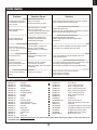
Trouble shooting
Problem Possible Cause Solution
Aircraft will not respond to
the throttlebut responds to
other controls.
-ESC is not armed.
-Throttle channel is reversed.
-Lower throttle stick and throttle trim to lowest settings.
-Reverse throttle channel on transmitter.
Extra propeller noise or
extra vibration.
-Damaged spinner, propeller,
motor or motor mount.
-Loose propeller and spinner parts.
-Propellor installed backwards.
-Replace damaged parts.
-Tighten parts for propeller adapter, propeller and spinner.
-Remove and install propeller correctly.
Reduced flight time or
aircraft underpowered.
-Flight battery charge is low.
-propeller installed backward.
-Flight battery damaged.
-Completely recharge flight battery.
-Replace flight battery and follow flight battery
instructions.
Control surface does not
move, or is slow to respond
to control inputs.
-Control surface, control horn,
linkage or servo damage.
-Wire damaged or connections
loose.
-Replace or repair damaged parts and adjust controls.
-Do a check of connections for loose wiring.
Controls reversed.
Channels are reversed in the
transmitter.
Do the control direction test and adjust controls for
aircraft and transmitter.
-Motor loses power
-Motor power pulses then
motor loses power.
-Damage to motor, or battery.
-Loss of power to aircraft.
-ESC uses default soft Low Voltage
Cutoff(LVC).
-Do a check of batteries, transmitter, receiver, ESC, motor
and wiring for damage(replace as needed).
-Land aircraft immediately and recharge flight battery.
LED on receiver flashes
slowly.
Power loss to receiver.
-Check connection from ESC to receiver.
-Check servos for damage.
-Check linkages for binding.
Spare parts list content
FMSEG101
FMSEG102
FMSEG103
FMSEG104
FMSEG105
FMSEG106
FMSEG107
FMSEG108
FMSEG109
FMSEG110
FMSEG111
FMSEG112
FMSEG113
FMSEG114
FMSEG115
FMSEG116
FMSEG117
FMSEG118
Fuselage
Main Wing Set
Vertical Stabilizer
Canard
Wingtip Missile
Underwing Missile
Oil Tank
Cockpit
Cowl
Refueling Probe
Canard Fastenings
Exhaust Nozzle plastic
LED Set
Wheel Set
Linkage Rod
Control Horns
Pipe
Screw Set
FMSEG119
FMSEG120
FMSEG121
FMSEG122
FMSEG123
FMSEG124
FMSEG125
FMSRE060
FMSRE061
FMS80MM12B-1
PRKV2100
PRESC014
PR13MGDP
PR13MGDR
FMS9GDP
FMS9GDR
FMSCON0016
Decal Sheet
Front Landing Gear Set
Main Landing Gear Set
Front Landing Gear System
Main Landing Gear System
Front Landing Gear Door
Main Landing Gear Door
EL Retract
EL Retract
80mm Ducted fan V2
3280-KV2100 inner runner motor
100A ESC
13g digital metal gear servo positive
13g digital metal gear servo reverse
9g digital gear servo positive
9g digital gear servo reverse
Multi-connector set
Visit our website: www.fmsmodel.com to see photo of this product. Enter the key word "ESC" in the search bar for the
stock ESC instruction manual.

15
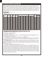
User Manual of Brushless Speed Controller
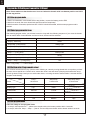
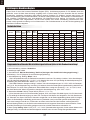
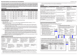
Programmable Items (The option written in bold font is the default setting)
Specifications
Thanks for purchasing our Electronic Speed Controller (ESC). High power system for RC model is very dangerous,
please read this manual carefully. In that we have no control over the correct use, installation, application, or
maintenance of our products,no liability shall be assumed nor accepted for any damages, losses or costs resulting
from the use of the product. Any claims arising from the operating, failure or malfunctioning etc. will be denied. We
assume no liability for personal injury, property damage or consequential damages resulting from our product or
our workmanship. As far as is legally permitted, the obligation to compensation is limited to the invoice amount of
the affected product.
Model
Cont
Current
Burst
Current
(≤10)
BEC
Mode
BEC
Output
BEC Output Capability Battery Cell
Weight
Weight
L*W*H
(mm)
6A
12A
12AE
15A
20A
30A
40A
40A-UBEC
50A-UBEC
60A-UBEC
60A-UBEC
80A-UBEC
80A-UBEC
6A
12A
12A
15A
20A
30A
40A
40A
50A
60A
60A
80A
80A
8A
15A
15A
20A
25A
40A
55A
55A
65A
80A
80A
100A
100A
Linear
Linear
Linear
Linear
Linear
Linear
Linear
Switch
Switch
Switch
N/A
Switch
N/A
5V/0.8A
5V/1A
2S Lipo 3S Lipo 4S Lipo 6S Lipo Lipo NiMH
5V/2A
5V/2A
5V/2A
5V/2A
5V/3A
5V/3A
5V/5A
5V/5A
N/A
5V/5A
N/A
3servos
3servos
5servos
5servos
5servos
5servos
5servos
5servos
8servos
8servos
8servos
2servos
4servos
4servos
4servos
4servos
4servos
5servos
8servos
8servos
8servos
5servos
6servos
6servos
6servos
6servos
6servos
6servos
2S
2-3S
2-3S
2-3S
2-3S
2-3S
2-3S
2-4S
2-4S
2-6S
2-6S
2-6S
2-6S
5-6 cells
5-9 cells
5-9 cells
5-9 cells
5-9 cells
5-9 cells
5-9 cells
5-12 cells
5-12 cells
5-18 cells
5-18 cells
5-18 cells
5-18 cells
5.5
9g
10g
16.5g
19g
37g
39g
43g
41g
63g
60g
82g
79g
32*12*4.5
38*18*6
38*18*7
48*22.5*6
42*25*8
68*25*8
68*25*8
65*25*12
65*29*10
77*35*14
86*38*12
86*38*12
86*38*12
1. Brake SettingEnabled / Disabled
2. Battery TypeLipo / NiMH
3. Low Voltage Protection Mode(Cut-Off Mode) Soft Cut-Off (Gradually reduce the output power) /Cut-Off
(Immediately stop the output power).
4. Low Voltage Protection Threshold(Cut-Off Threshold)Low / Medium / High
1) For lithium battery, the battery cell number is calculated automatically. Low / medium / high cutoff voltage for
each cell is 2.85V/3.15V/3.3V. For example: For a 3S Lipo, when "Medium" cutoff threshold is set, the cut-off
voltage will be:3.15*3=9.45V.
2) For NiMH battery, low / medium / high cutoff voltages are 0%/50%/65% of the startup voltage (i.e. the initial
voltage of battery pack), and 0% means the low voltage cut-off function is disabled. For example: For a 6 cells
NiMH battery, fully charged voltage is 1.44*6=8.64V, when "Medium"cut-off threshold is set, the cut-off voltage
will be: 8.64*50%=4.32V
5. Startup ModeNormal /Soft /Super-Soft (300ms / 1.5s / 3s)
a) Normal mode is suitable for fixed-wing aircraft. Soft or Super-soft modes are suitable for helicopters. The
initial acceleration of the Soft and Super-Soft modes are slower, it takes 1.5 second for Soft startup or 3 seconds
for Super-Soft startup from initial throttle advance to full throttle. If the throttle is completely closed (throttle stick
moved to bottom position) and opened again (throttle stick moved to top position) within 3 seconds after the first
startup, the re-startup will be temporarily changed to normal mode to get rid of the chance of a crash caused by
slow throttle response. This special design is suitable for aerobatic flight when quick throttle response is needed.
6. TimingLow / Medium / High,( 3.75°/15°/26.25°) Usually, low timing is suitable for most motors. To get higher
speed, High timing value can be chosen.

16
Begin To Use Your New ESC
Protection Function
Trouble Shooting
IMPORTANT! Because different transmitter has different throttle range, please calibrate throttle range
before flying.
1.Switch on the transmi t ter, move throttle stick to the top position.
2.Connect battery pack to the ESC, and wait for about 2 seconds.
3.The "Beep-Beep-" tone should be emitted, means the top point of throttle range has been confirmed.
4.Move throttle stick to the bottom position, several "beep-" tones should be emitted to present the amount of
battery cells.
5.A long "Beep-" tone should be emitted, means the lowest point of throttle range has been correctly confirmed.
1.Move throttle stick to bottom position and then switch on transmitter.
2Connect battery pack to ESC, special tone like "♪ 123" means power supply is OK.
3.Several "beep-" tones should be emitted to present the amount of lithium battery cells.
4.When self-test is finished, a long"beep-----" tone should be emitted.
5.Move throttle stick upwards to go flying.
1. Start up failure protection: If the motor fails to start within 2 seconds of throttle application, the ESC will cut-off
the output power. In this case, the throttle stick MUST be moved to the bottom again to restart the motor. (Such a
situation happens in the following cases: The connection between ESC and motor is not reliable, the propeller or
the motor is blocked, the gearbox is damaged, etc.)
2. Over-heat protection: When the temperature of the ESC is over about 110 Celsius degrees, the ESC will reduce
the output power.
3.Throttle signal loss protection: The ESC will reduce the output power if throttle signal is lost for 1 second, further
loss for 2 seconds will cause the output to be cut-off completely.
User Manual of Brushless Speed Controller
Throttle range setting (Throttle range should be reset whenever a new transmitter is being used)
Normal startup procedure
Trouble
After power on, motor does not work,
no sound is emitted
After power on, motor does not work,
such an alert tone is emitted:
"beep-beep-, beep-beep-,beep-beep-"
(Every "beep-beep-" has a time interval
of about 1 second)
After power on, motor does not work,
such an alert tone is emitted:
"beep-, beep-, beep- "(Every "beep-" has
a time interval of about 2 seconds)
After power on, motor does not work,
such an alert tone is emitted:
"beep-, beep-, beep-" (Every "beep-" has
a time interval of about 0.25 second)
After power on, motor does not work, a
special tone " ♪56712" is emitted after 2
beep tone (beep-beep-)
The motor runs in the opposite direction
After power on, motor does not
work,no sound is emitted
Input voltage is abnormal, too high
or too low
Throttle signal is irregular
The throttle stick is not in the
bottom (lowest) position
Direction of the throttle channel is
reversed, so the ESC has entered
the program mode
The connection between ESC and
the motor need to be changed
Check the power connection.
Replace the connector.
Check the voltage of battery pack
Check the receiver and transmitter
Check the cable of throttle channel
Move the throttle stick to bottom
position
Set the direction of throttle
channel correctly
Swap any two wire connections
between ESC and motor
Possible Reason Action

17
1.Switch on transmitter, move throttle stick to top position, connect the battery pack to ESC
2.Wait for 2 seconds, the motor should emit special tone like "beep-beep-"
3.Wait for another 5 seconds, special tone like "♪56712" should be emitted, which means program mode is
entered
NO.1 Enter program mode
After entering program mode, you will hear 8 tones in a loop with the following sequence. If you move the throttle
stick to bottom within 3 seconds after one kind of tones, this item will be selected.
You will hear several tones in loop. Set the value matching to a tone by moving throttle stick to top when you hear
the tone, then a special tone "♪1515" emits, means the value is set and saved. (Keeping the throttle stick at top,
you will go back to Step 2 and you can select other items; or moving the stick to bottom within 2 seconds will exit
program mode directly) .
There are 2 ways to exit program mode:
1. In step 3, after special tone " ", please move throttle stick to the bottom position within 2 seconds.
2. In step 2, after tone "beep-----beep-----"(that is: The item #8),move throttle stick to bottom within 3 seconds.
Note: 1 long "beep-----" = 5 short "beep-"
NO.2 Select programmable items
NO.3 Set item value (Programmable value)
NO.4 Exit program mode
Note: Please make sure the throttle curve is set to 0 when the throttle stick is at bottom position and 100%
for the top position.
Program the ESC with your transmitter (4 Steps)
Prompt tone
"beep"(1 short tone)
"beep-beep-"(2 short tone)
"beep-beep-beep-"(3 short tone)
"beep-beep-beep-beep-"(4 short tone)
"beep——"(1 long tone)
"beep——beep-"(1 long 1 short)
"beep——beep-beep-1 long 2 short
"beep——beep——"(2 long tone)
Selected item
brake
battery type
cutoff mode
cutoff threshold
startup mode
timing
set all to default
exit
Tones "beep-"
1 short tone
"beep-beep-"
2 short tones
"beep-beep-beep"
3 short tones
Items
Brake
Battery type
Cutoff mode
Cutoff threshold
Start mode
Timing
Off
Lipo
Soft-Cut
Low
Normal
Low
On
NiMH
Cut-Off
Medium
Soft
Medium
High
Super soft
High

WARNUNG: Lesen Sie die GESAMTE Bedienungsanleitung, um sich vor der Inbetriebnahme mit den Funktionen des Produkts
vertraut zu machen.
Wenn das Produkt nicht ordnungsgemäß bedient wird, kann dies zu Schäden am Produkt oder persönlichem Eigentum führen
und schwere Verletzungen verursachen.Dieses Produkt ist kein Spielzeug! Es muss mit Vorsicht und gesundem Menschenver-
stand betrieben werden. Andernfalls kann es zu Verletzungen oder Schäden am Produkt oder anderen Sachwerten führen.
Dieses Produkt ist nicht für den Betrieb durch Kinder ohne direkte Aufsicht von Erwachsenen vorgesehen.
Diese Anleitung enthält Hinweise zu Sicherheit und Wartung. Es ist wichtig, dass vor der Verwendung alle Anweisungen und
Warnungen in der Anleitung gelesen und befolgt werden, um Schäden oder schwere Verletzungen zu vermeiden.
Warnhinweise
VORSICHT: Befolgen Sie immer die Anweisungen des Herstellers zur sicheren Verwendung und Entsorgung
von Batterien. Durch falsche Handhabung von Li-Po-Batterien können Feuer, Sachschäden oder schwere
Verletzungen verursacht werden.
Seien Sie sich über alle Risiken klar, die mit dem Umgang von Lithium Polymer (LiPo) Akkus verbunden sind.
Wenn die Akkus zu irgendeinem Zeitpunkt anschwellen oder aufblähen, verwenden Sie diese auf keinen Fall
mehr!
Um die Lebensdauer des Akkus zu verlängern sollten dieser bei Zimmertemperatur in einem trockenen Bereich
gelagert werden. Bewahren Sie den Akku oder das Modell nicht in einem Auto oder in direktem Sonnenlicht
auf. Wenn der Akku über einen längeren Zeitraum zu hohen Temperaturen ausgesetzt wird kann dieser
beschädigt werden oder sogar Feuer fangen.
Verwenden Sie niemals ein NiMh-Ladegerät, um Li-Po-Akkus aufzuladen. Wenn der Akku nicht mit einem
Li-Po-kompatiblen Ladegerät geladen wird, kann dies zu einem Brand führen, der zu Personen- und Sachschäden
führen kann.
Niemals Li-Po Zellen unter 3V entladen.
Lassen Sie Akkus beim Laden niemals unbeaufsichtigt.
Laden Sie niemals beschädigte Akkus auf.
Aufladen des LiPo-Akkus: Verwenden Sie ein Ladegerät, das die Li-Po-Batterie sicher aufladen kann. Lesen
Sie vor dem Gebrauch die Anweisungen des Ladegeräts sorgfältig durch. Achten Sie beim Laden des Akkus
darauf, dass sich der Akku auf einer hitzebeständigen Oberfläche befindet. Es wird auch dringend empfohlen,
den Li-Po Akku in einem feuerbeständigen LiPo-Koffer zu laden. LiPo Koffer finden Sie bei Ihrem Fachhändler
oder im Internet.
Als Benutzer dieses Produkts sind Sie allein dafür verantwortlich dieses Produkt so zu betreiben, dass weder Sie selbst noch
andere gefährdet oder Schäden am Produkt oder Eigentum anderer verursacht werden.
Dieses Modell wird von einem Funksignal gesteuert, das von vielen Quellen außerhalb Ihrer Kontrolle gestört werden kann.
Solche Störungen können zu einem vorübergehenden Kontrollverlust führen. Daher sollte immer einen Sicherheitsabstand zu
Personen und Gebäuden eingehalten werden.
Altersempfehlung: Nicht für Kinder unter 14 Jahren. Dies ist kein Spielzeug.
• Betreiben Sie Ihr Modell niemals mit leeren Senderbatterien.
• Betreiben Sie Ihr Modell immer in einem offenen Bereich, abseits von Gebäuden, Verkehr oder Personen.
• Befolgen Sie die gesetzlichen Regelungen Ihres Landes zum Betrieb von ferngesteuerten Modellflugzeugen.
• Befolgen Sie sorgfältig die Anweisungen und Warnungen für dieses und alle unterstützenden Geräte, die Sie verwenden
(Ladegeräte, wiederaufladbare Akkus usw.).
• Bewahren Sie alle Chemikalien, Kleinteile und elektrischen Geräte außerhalb der Reichweite von Kindern auf.
• Feuchtigkeit verursacht Schäden an der Elektronik. Vermeiden Sie, dass die Produkte Wasser ausgesetztwerden, die nicht
speziell für diesen Zweck entworfen und geschützt sind.
• Nehmen Sie Teile des Produkts niemals in den Mund, da dies zu schweren Verletzungen oder sogar zum Tod führen kann.
Sicherheitsvorkehrungen
Hinweise zu LiPo-Akkus
18

19
Inhalt
Einleitung
Die von der französischen Firma Dassault entworfene Rafale
ist ein äußerst manövrierfähiger Delta Jet. Dank ihrer einzig-
artigen Flugeigenschaften im Nahkampf, im Flugbetrieb und
im Luft-Boden-Angriff hat die Rafale weltweite Erfolge errun-
gen.
Wie ihr maßstabsgetreues Pendant zeichnet sich die FMS
80mm Rafale durch ein attraktives Farbschema, zahlreiche
Scale Details und voll funktionsfähige Canards aus, wodurch
das Flugzeug im Vergleich zu anderen heute auf dem Markt
erhältlichen 80mm EDF-Flugzeugen wirklich einzigartig ist.
Entwickelt, um sowohl das Aussehen als auch die Leistung
des echten Flugzeugs nachzubilden, hat FMS seine jahrzehn-
telange Erfahrung in die Konstruktion der 80mm Rafale einge-
bracht. Details wie Pilot, Cockpitausstattung, Verkleidungen,
abnehmbare Bewaffnung, Zusatztanks, Betankungssonde,
Zielerfassungssensor, usw. - dynamische Merkmale wie funk-
tionelle LED-Navigations- und Landelichter, stoßdämpfendes
elektrisches Einziehfahrwerk, funktionelle Canards und Klap-
pen usw.
Wie alle anderen FMS-Flugzeuge wurde auch die 80mm
Rafale mit dem Ziel entwickelt, die Bauzeit auf ein Minimum
zu reduzieren. Dank der Verwendung von Schrauben, Verrie-
gelungen und Schnellverbindern können erfahrene Konstruk-
teure den Bauprozess in nur 5 Minuten abschließen.
Funktionen wie Delta-Mixing, sequentielle Fahrwerksklappen,
alternierende Blitz-Navigationslichter, Bugfahrwerkslichter,
verlangsamte Klappen usw. werden alle von einer zentralen
Steuerplatine gesteuert. Ein 80 mm EDF mit 12 Blättern, ein
3280-Innenläufermotor und und ein 100 A Hochleis-
tungs-Regler führen problemlos Manöver realistisch durch.
Lieferumfang
Bitte überprüfen Sie vor der Endmontage ob alle Teile des
Modells enthalten sind. Das folgende Bild zeigt den Inhalt
des Kits.
Sollten Teile fehlen notieren Sie sich bitte den Namen und
die Teilenummer (siehe Ersatzteilliste am Ende dieser
Bauanleitung) und kontaktieren Sie Ihren lokalen Händler
oder senden Sie uns eine E-Mail an info@d-power-modell-
bau.com.
Spannweite: 974mm
Länge: 1409mm
Fluggewicht: ca. 3280g
Motor: 3280 KV2100
Flächenbelastung: 85.2g/dm²
Flächeninhalt: 38.5dm²
Regler: 100A
Servo: 7x 13g, 2x 9g
Empfohlener Akku: 22.2V 4000-5000mAh 45C
Technische Daten
Eigenschaften:
• 3280-2100KV Platin-Edition-Innenläufer mit einem
leistungsstarken 100A Regler
• Delta-Flügel-Design mit Canards und funktionalen Klappen
• stoßdämpfendes CNC-Fahrwerk aus Metall
• Funktionelle Navigations- und Landelichter
• Zentrale Funktionssteuerung
• Liebevoll nachgebildete funktionale und statische Details
• Farbdesign auf Wasserbasis
Einleitung
Lieferumfang
Monatge des Modells
Einsetzen des Akkus
Anschließen an den Empfänger
Flugvorbereitungen
Montage der Gabelköpfe
Ruderhorn- und Servoarm-Einstellungen
Schwerpunkt
Vor dem Erstflug
Fluggrundlagen
Problmelösungen
Ersatzteile
Bedienungsanleitung zum Regler
19
19
20
26
26
26
28
28
28
29
29
30
30
31
...............................................................
...........................................................
...............................................
................................................
.................................
..................................................
..........................................
.....................
...........................................................
......................................................
.......................................................
.....................................................
..............................................................
...............................
Lassen Sie sich die Chance nicht entgehen, eines der am
besten aussehenden modernen Jagdflugzeuge zu besitzen -
die FMS 80mm Rafale!
A. B.
C.
F. G. H.
I. J.
D.
E.
A:
B:
C:
D:
Rumpf
Nase
Tragflächen
Waffen-Set
E:
F:
G:
H:
Tanks
Seitenleitwerk
Flächenverbinder
Kraftstoff Sonde
I:
J:
Canard
Schrauben Set
HKM3.0x16*4
HKM3.0x20*2
4x3mm set screw*2
Seite wird geladen ...
Seite wird geladen ...
Seite wird geladen ...
Seite wird geladen ...
Seite wird geladen ...
Seite wird geladen ...
Seite wird geladen ...
Seite wird geladen ...
Seite wird geladen ...
Seite wird geladen ...
Seite wird geladen ...
Seite wird geladen ...
Seite wird geladen ...
Seite wird geladen ...
-
 1
1
-
 2
2
-
 3
3
-
 4
4
-
 5
5
-
 6
6
-
 7
7
-
 8
8
-
 9
9
-
 10
10
-
 11
11
-
 12
12
-
 13
13
-
 14
14
-
 15
15
-
 16
16
-
 17
17
-
 18
18
-
 19
19
-
 20
20
-
 21
21
-
 22
22
-
 23
23
-
 24
24
-
 25
25
-
 26
26
-
 27
27
-
 28
28
-
 29
29
-
 30
30
-
 31
31
-
 32
32
-
 33
33
-
 34
34


FMS Dassult Rafale Bedienungsanleitung
- Kategorie
- Ferngesteuertes Spielzeug
- Typ
- Bedienungsanleitung
in anderen Sprachen
- English: FMS Dassult Rafale Owner's manual
Verwandte Artikel
-
FMS 1220mm Super EZ V4 Bedienungsanleitung
-
FMS FMM129P Bedienungsanleitung
-
-
-
-
-
-
-
-
Andere Dokumente
-
ParkZone PKZ5275 Bedienungsanleitung
-
E-flite EFLA1040B Bedienungsanleitung
-
Modster Piper J3 Bedienungsanleitung
-
 Staufenbiel L-13 Blanik Benutzerhandbuch
-
 Reely 1460688 Bedienungsanleitung
-
-
-
-
Arrows HOBBY 1300mm Benutzerhandbuch
-

