
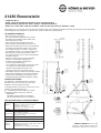
21436 Boxenstativ
- Tragkraft: 40 kg
- Stabil, sicher und bedienerfreundlich; klein zusammenlegbar
- Gleichermaßen geeignet für: Heim-, Objekt-, öffentlicher Bereich
- Höhe: min. 1440 / max. 2230 mm, Fußkreis 1150 mm, Auszug ø 35 mm, Gewicht: 3,5 kg
SICHERHEITSHINWEISE
- Max. zentrische Last: 40 kg
- Vor und nach Benutzung Stativ auf Schäden
- überprüfen. Beschädigte Stative dürfen nicht
- weiter eingesetzt werden.
- Stativ darf nicht einseitig belastet werden.
- Der Untergrund muß tragfähig und eben sein.
- Entsprechender Einsatz von Personal erforderlich
- (2 fachlich und körperlich geeignete Personen).
- Vor Installation prüfen, ob Stativ, Lautsprecher
- und Hilfsmittel (Leitern u.a.) funktionstüchtig sind.
- Auf geeignetes Lautsprechermaterial achten;
- d.h. die Flanschbuchse muss über richtige Größe
- und Güte verfügen.
- Unbefugte vom belasteten Stativ fernhalten:
- Schutz vor Stolperfallen, Kippgefahren
- Sicherheit der Installation überwachen:
- - feste Schraubverbindungen.
- - Die maximale Standfestigkeit erreicht das Stativ
--bei waagerecht eingestellten Fußstreben.
- - Niemals unkontrolliert Rastbolzen und
--Klemmschraube des Auszugrohres lösen.
- ACHTUNG: das Verschieben des belasteten Stativs
- kann zu Beschädigungen des Fußgestells führen.
- Aufmerksame Handhabung erforderlich, da die
- Verstellmöglichkeiten Einklemmgefahren bergen.
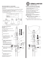
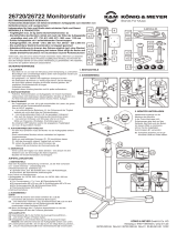
AUFBAUANLEITUNG
Der Aufbau des 21436 Boxenstativ ist einfach.
Alle Teile sind schon montiert, das Stativ muß
lediglich in Position gebracht werden.
(1) Klemmschraube der Dreieckschelle etwas lösen.
(2) Beine auseinanderziehen bis...
(3) ...Verbindungsstreben waagerecht stehen.
(4) Klemmschraube wieder fest anziehen.
(4) BEACHTE:
(4) Handkraft genügt; überfestes Anziehen
(4) belastet die Bauteile und ist zu vermeiden.
TECHNISCHE DATEN / SPEZIFIKATIONEN
Vielen Dank, dass Sie sich für dieses Produkt entschieden haben. Diese Anleitung informiert Sie über alle wichtigen Schritte bei Aufbau
und Handhabung. Wir empfehlen, sie auch für den späteren Gebrauch aufzubewahren.
KÖNIG & MEYER GmbH & Co. KG
Kiesweg 2, 97877 Wertheim, www.k-m.de
21436-009-55 Rev.10 03-79-172-00 3/17
Material
- Grund-, Fußrohre: Aluminium
- Auszugrohr, Streben, Rastbolzen: Stahl
- Schellen: Polyamid (PA)
- Parkettschoner, Stoßdämpfer: (TPE)
Traglast - max. 40 kg zentrische Last
Abmessungen
- max. Fußkreis ø 1150 mm
- Höhe: 1440-2230 mm (bei max. Fußkreis)
- Auszugrohr: ø 35 mm
Packmaß, kg B x T x H: 122 x 141 x 1183 mm, 3,5 kg
Karton, kg B x T x H: 130 x 120 x 1185 mm, 4,2 kg
Zubehör
(optional)
- Tragetasche 21311 (für ein oder zwei 21436)
- K&M-Flanschbuchsen (z.B. 19580, 19654, 19656 etc.)
- Anschraubflansch (24281)
- Adapterhülse 21326: ø 38 mm (= US-Variante)

PRÜFEN, INSTANDHALTEN, REINIGEN
- Schonender Umgang mit dem Stativ erhält die
- Teleskopierbarkeit, die Tragkraft und die
- Sicherheit der Installation.
- Bei Wartungsarbeiten -stets im unbelasteten
- Zustand- auf evtl. Gefährdungen achten
- (Einklemmen, Anstoßen, Kippen).
- Zur Reinigung und Pflege am besten ein leicht
- feuchtes Tuch und ein nicht scheuerndes
- Reinigungsmittel benutzen.
FEHLERSUCHE (F) und BESEITIGUNG (B)
(F): Stativ wackelt
(F): (B): Bodenunebenheiten beseitigen
(F): (B): Fußgestell in max. Auslage bringen und
(F): (B): Klemmschraube anziehen
(F): Auszugrohr wackelt bzw. fährt ein unter Last
(F): (B): Rastbolzen prüfen, Klemmschraube anziehen
ACHTUNG!
Unterschätzen Sie nicht das Gewicht des Lautsprechers (max. 40 kg),
- aufsetzen und ausfahren des Lautsprechers muss durch fachlich
- und körperlich geeignetes Personal erfolgen,
- Auszugrohr während der Höhenverstellung mit festem Griff halten und
- stets mit Rastbolzen sichern.
DAS BEWEGEN DER LAST
Beteiligte:
EP - Erste Person:
bedient das Auszugrohr mit der Last
ZP - Zweite Person:
bedient Klemmschraube und Rastbolzen
der Spannschelle
EP
1. hält Auszugrohr fest
ZP
2. lockert Klemmschraube
3. betätigt Druckknopf um
3. Rastbolzen zu lösen und
3. hält Grundrohr fest
EP
4. stemmt Auszugrohr und Box in
4. ungefähr gewünschte Höhe;
4. BEACHTE:
4. zum einfachen Auffinden der
4. Rastbohrung sollte sich diese
4. in diesem Moment kurz über
4. der Spannschelle befinden
ZP
5. lässt Druckknopf los, damit
5. der Bolzen ins Auszugrohr
5. einrasten kann
EP
6. lässt Auszugrohr langsam ab
6. bis Rastbolzen in Loch einrastet
ZP
7. dreht Klemmschraube fest
7. (Handkraft genügt)
Das Einfahren der Last erfolgt in
umgekehrter Reihenfolge.
BENUTZERHINWEISE / FUNKTIONEN
LAUTSPRECHER AUFBRINGEN und AUSFAHREN

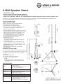
21436 Speaker Stand
- Load capacity: 40 kg
- Stable, safe, user-friendly and folds compactly
- Similarly adapted for home, property, public area
- Height: min. 1430 / max. 2240 mm, base spread diameter 1150 mm, telescopic section ø 35 mm, weight: 3.5 kg
SAFETY INSTRUCTIONS
- Max. central capacity: 40 kg
- Before and after use check stand for damage.
- Damaged Stands may not be used.
- The stand must not be loaded unevenly.
- The ground must be even and suitable for a stand.
- 2 technicians are needed to set up the stand
- (physical strength required).
- Before installing the stand check that the tripod, loud
- speakers and other devices (cables) function correctly.
- Check that the loud speakers are suitable, i.e. that
- the flange bushing is the correct size and type.
- Do not allow unauthorised persons near the stand
- when weighted: make sure there is no danger of
- tripping and that the stand cannot tip.
- Check the stand is safe:
- - are the screws tight?
- - The stand is most stable when the leg struts are
--horizontal and level.
- - Be especially careful when removing the locking
--pin and clamping screw from the telescopic section.
- WARNING: Moving the stand when weighted could
- damage the leg sections.
- When adjusting the stand take care: potential
- pinching hazard.
ASSEMBLY INSTRUCTIONS
TECHNICAL DATA
Thank you for choosing this product. These instructions describe the procedure for properly assembling and adjusting the stand.
We recommend keeping the instructions as you may need them at a later date.
KÖNIG & MEYER GmbH & Co. KG
Kiesweg 2, 97877 Wertheim, www.k-m.de
21436-009-55 Rev.10 03-79-172-00 3/17
Materials
- base, leg: aluminum
- telescopic sections, struts and locking pins: steel
- shaft collar: polyamide (PA)
- end caps, shock absorber: (TPE)
Load capacity - max. 40 kg central load
Dimensions
- max. base spread ø 1150 mm
- height: 1440-2230 mm (for max. base)
- telescopic section: ø 35 mm
Packed dimensions, kg W x D x H: 122 x 141 x 1183 mm, 3.5 kg
Delivery box, kg W x D x H: 130 x 120 x 1185 mm, 4.2 kg
Accessories (optional)
- carrying case 21311 (for one or two 21436)
- K&M flange adapter (e.g. 19580, 19654, 19656, etc.)
- scrow-on adapter (24281)
- adapter sleeve 21326: ø 38 mm (= US variation)
It is easy to set-up the 21436 speaker stand. All parts
are ready to use, the stand only needs to be positioned.
(1) Slightly loosen the clamping screw on the tripod
shaft sleeve.
(2) Straddle the legs until...
(3) ...the strut sections are horizontal.
(4) Re-tighten the clamping screw.
(4) NOTE:
(4) Normal hand strength is sufficient; please avoid
(4) over-tightening the screw as this will strain the
(4) stand sections.

TESTING, MAINTENANCE, CLEANING
- Treating the stand with care will help preserve its
- telescopic function, weight capacity and maintain
- safety.
- Only carry out work on the stand when it is not
- weighted and be aware of potential hazards
(pinching,
- tipping, and jolting).
- Use a slightly damp cloth with a non-scouring
- cleaning agent to clean the stand.
(P) PROBLEM and (C) CORRECTION
(P): Stand wobbles
(P): (C): Ensure the ground is even
(P): (C): Extend the legs to max. position and tighten
(P): (C): camping screw
(P): Telescopic section wobbles, slips down when
(P): weighted
(P): (C): Check locking pin, tighten clamping screw
WARNING!
Do not underestimate the weight of the loud speakers (max. 40 kg),
- The loud speakers must be mounted, the stand extended and straddled
- by technicians who have the physical capacity for the procedure,
- When adjusting the stand height, hold the stand securely and always
- lock in place with the locking pin.
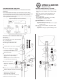
TO ADJUST THE STAND WHEN WEIGHTED
Participants:
FP – first person:
moves the telescopic section with the weight
SP – second person:
operates the clamping screw and
the locking pin on the shaft collar
FP
1. holds the telescopic section securely
SP
2. loosens the clamping screw
3. loosens the locking pin by
3. pressing the button while holding
3. the shaft securely
FP
4. moves the telescopic section and
4. speaker to the required height;
4. NOTE:
4. the locking bore holes should be easy
4. to locate above the shaft sleeve
SP
5. releases the button so
5. the pin can snap back
5. intoplace in the telescopic
5. section
FP
6. Slowly lets go of the telescopic section
6. and the locking pin snaps into a bore hole
SP
7. Tightens the clamping screw
7. (hand strength is sufficient)
To retract the stand and load, follow the
instructions in the reverse order.
USER INFORMATION / FUNCTIONS
WHEN MOUNTING SPEAKERS and STRADDLING STAND
Application examples (not included in the delivery)
loud
speaker
-
 1
1
-
 2
2
-
 3
3
-
 4
4


in anderen Sprachen
- English: K&M 21436 Operating instructions
Verwandte Artikel
Andere Dokumente
-
König & Meyer Ring Lock Datenblatt
-
-
 OUT MEYER Benutzerhandbuch
-
 KONIG MEYER 26720-022-55 Benutzerhandbuch
-
Genelec 8000-400 Genelec Design stand Benutzerhandbuch
-
-
-
-
-

