Seite wird geladen ...

24173 Boxenwandhalterung
- max. Tragkraft 25 kg
- Flexibel einstellbarer Haltearm:
Ausrichtung: stufenlos schwenkbar in der Horizontalen
Neigung: fixierbar in 6 Positionen (0° -5° -10° -15° -20° -25° -30°)
Wandabstand des Aufsteckbolzens: 4 mögliche Varianten (350 - 380 - 410 – 440 mm)
- mit Boxen-Aufsteckbolzen ø35 x 84 mm (passend für Flanschbuchsen ø 35-36 mm)
SICHERHEITSHINWEISE
- Vor und nach Benutzung Halterung auf Schäden überprüfen. Beschädigte Halterungen dürfen nicht wiedereingesetzt werden.
- Max. zentrische Last: 25 kg
- Nicht für Außen- und Feuchträume
- Örtlich gültige Befestigungsvorschriften beachten (evtl. abweichend von angegeben Beispielen)
- Montage nur an geeigneter Wand mit entsprechendem Montagematerial (nicht im Lieferumfang);
- Beispiele siehe unter Punkt 4,5,6. Setzanweisungen der Dübelhersteller bitte beachten.
- Ungeeignet sind Wände die zu schwach sind; ebenso ist auf Strom- und Wasserleitungen zu achten. Im Zweifelsfall einen Fachmann
- zu Rate ziehen.
- Montage nur durch ausgebildetes Installationspersonal
- Auf feste Schraubverbindungen achten, insbesondere bei Einstellung der Boxenneigung
- Aufmerksame Handhabung erforderlich, da die Verstellmöglichkeiten Einklemmgefahren bergen
- Diese Anleitung informiert über alle wichtigen Schritte bei Aufbau und Handhabung. Wir empfehlen, sie auch für später aufzubewahren.
Vielen Dank, daß Sie sich für dieses Produkt entschieden haben. Diese Anleitung informiert Sie über alle wichtigen Schritte bei Aufbau
und Handhabung. Wir empfehlen, sie auch für den späteren Gebrauch aufzubewahren.
AUFBAUANLEITUNG
Die Boxenwandhalterung 24173 ist bereits komplett
vormontiert und muss lediglich noch an der Wand
befestigt werden (siehe SICHERHEITSHINWEISE).
1. VORBEREITUNG
1 Wandhalteplatte senkrecht ausrichten
2 Bohrlöcher markieren 6x
3 Dübellöcher bohren 6x
3 - 8 mm bei Bolzen-Anker (Bsp. A)
3 - 10 mm bei Rahmendübel (Bsp. B)
2. BEFESTIGUNGSBEISPIELE
4 Dübelloch
4 vorbereiten
- Loch bohren
- und ausblasen
- Loch bohren
- ansenken
- ausblasen
- Anker
- einschlagen
-Rahmendübel
- einschlagen
- Wandhalter platzieren,
- U-Scheibe setzen,
- Mutter (SW13) mit
- 20Nm anziehen
-Wandplatte
- anbringen
- Schraube
- eindrehen
5 Anker/Dübel
5 setzen 6x
6 Wandplatte
6 festschrauben
A. Betonwand - Bsp.: Bolzen-Anker
A. M8 x 65 mm
C. Einspritzmörtel-Verankerungen
C. a. ohne Siebhülse für Vollmauerwerk und Beton
C. b. mit Siebhülse für Hohlkammersteine / wahlweise mit Anker-Gewindestange M8 oder Innengewindehülse M8
C. Vorteile: Befestigung arbeitet spreizdruckfrei, dadurch kann die Halterung beliebig oft ausgewechselt werden und erlaubt eine
C. Vorteile: randnahe Montage (nicht unter 100 mm Abstand). Genaue Montagehinweise entnehmen Sie bitte den
C. Vorteile: Beipackinformationen der Produkte.
B. Lochsteine - Bsp.: Rahmendübel 10 x 100 mm
B. mit Holzschraube DIN571 ø7 x 105 mm

- Bei Wartungsarbeiten auf evtl. Gefährdungen achten
- Zur Reinigung am besten ein leicht feuchtes Tuch und ein
nicht scheuerndes Reinigungsmittel benutzen.
FEHLERSUCHE (F) und BESEITIGUNG (B)
F: Bauteile der Halterung wackeln
F: B: Schraubverbindungen festziehen
F: Lautsprecher taumelt auf dem Steckbolzen
F: B: Mutter unterhalb des Steckbolzens festziehen
F: B: Lautsprecher überprüfen, insbesondere Güte
F: B: und Abmessung der Flanschbuchse (ø35-36 mm)
3. BEFESTIGUNG DES LAUTSPRECHERS
4. EINSTELLUNGEN & ABMESSUNGEN
7 Zunächst ist zu prüfen ob der Lautsprecher über
7 eine bezüglich Abmessungen (ø 35-36 mm) und
7 Güte geeignete Flanschbuchse verfügt.
8 Flanschbuchse des Lautsprechers möglichst
8 sanft auf den Aufsteckbolzen der Halterung
8 setzen. Zu schnelles Aufsetzen oder gar das
8 "Fallenlassen" des Lautsprechers kann zu
8 Schäden an Box und Halterung führen und
8 ist strikt zu vermeiden.
NEIGUNG
Der Neigungswinkel des Boxenhalterohrs
kann in Stufen fixiert werden zu:
- 0° - 5° - 10° - 15° - 20° - 25° - 30°
BEACHTE:
Die Verstellung des Neigungswinkels
erfordert die Entfernung der oberen
Schraubverbindung und darf nur
OHNE TRAGLAST erfolgen.
19 Die obere Verschraubung des
19 desSchwenkgelenks (dort
19 wo sichdie 7 Löcher
19 befinden) vollständig
19 auseinandernehmen
10 Boxenhalterohr wie gewünscht
10 neigen und diese Position ...
11 ...durch erneutes Abstecken und
11 Anziehen der Schraubverbindung
11 wieder sichern.
RICHTUNG
Der Schwenkbereich des Boxenhalterohres
erstreckt sich über max.146°. Innerhalb
dieses Spektrums kann jede Position
gewählt werden.
12 Drehachse ist zähgängig eingestellt,
12 d.h. die Verschraubung wird nicht
12 gelöst.
13 Lautsprecher fassen und in
13 gewünschte Richtung schwenken.
PRÜFEN, INSTANDHALTEN, REINIGEN
TECHNISCHE DATEN / SPEZIFIKATIONEN
Material
Wandplatte, Schwenkgelenk, Halterohr und
Steckbolzen: Stahl, pulverbeschichtet, schwarz
Verschraubung: Stahl, verzinkt
Kappen, Dämpfung: Kunststoff (PE, PA)
Traglast Lautsprecher max. bis 25 kg
Maße
B x T x H: 120 x 486 x 324 mm,
Karton: 150 x 230 x 565 mm
Gewicht netto: 3,7 kg; brutto: 4,3 kg
Zubehör
(optional)
21326 Adapterhülse
für ø 38 mm (US-Dimension)
KÖNIG & MEYER GmbH & Co. KG
Kiesweg 2a, 97877 Wertheim, www.k-m.de
24173-000-55 Rev.1 03-80-361-00 4/18
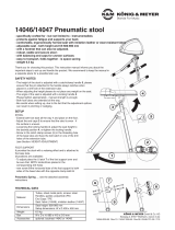
Beispiele

24173 Speaker wall mount
- Load bearing weight: max 25 kg
- Flexible adjustable support arm:
Direction: variable horizontal swivel
Angle: set in 6 positions (0° -5° -10° -15° -20° -25° -30°)
Wall distance from the pin: 4 possible options (350 - 380 - 410 - 440 mm)
- with loudspeaker pin ø35 x 84 mm (suitable for flange bushings ø 35-36 mm)
SAFETY NOTES
- Check for damage prior to and after use. Damaged plates/brackets may not be used.
- Maximum centered load: 25 kg
- Not suitable for outdoors or moist rooms
- Observe the local mounting regulations (they may deviate from the examples presented here).
- Only mount on suitable walls with the corresponding assembly material (not included in the delivery)
- Example - see Point 4,5,6. Observe the placement instructions provided by the anchor manufacturer.
- Walls, that are too weak or have electrical and water conduits. In case of doubt consult a qualified technician.
- Only use trained technicians to assemble the system
- Ensure that the screws are tight and load-bearing, in particular as regards the setting of the loudspeaker angle.
- Careful and attentive handling is required when adjusting the stand - due to the possibility of pinching or wedging your hand.
- The instructions provide directions to all of the important setup and handling steps. We recommend you keep these instruction
- for future reference.
Thank you for choosing this product. This instruction manual informs you about the important steps to set up and handle the product.
We recommend to keep the manual in a separate place for a possible later use.
SETUP INSTRUCTIONS
The loud speaker wall mount 24173 come pre-
assembled and only needs to be mounted.
to the wall (see SAFETY NOTES).
1. PREPARATION
1 Wall mount plate is placed vertically
2 Mark the drill holes 6x
3 Drill the anchor holes 6x
3 - 8 mm for anchor bolts (Example A)
3 - 10 mm for sleeve anchors (Example B)
2. MOUNT EXAMPLES
4 Anchor hole
4 prepare
- drill,
- blow out hole
- Drill hole
- flush
- blow out
- Drive in the
- anchor
- Drive in the
- frame anchor
- Place Wall mount,
- Set washer,
- Tighten nut (SW13)
- with 20Nm torque
- Mount
- wall plate
- Attach with
- screws
5 Insert
5 anchor 6x
6 Attach wall
6 plate securely
A. Concrete wall – e.g.: Anchor bolt
A. M8 x 65 mm
C. Grout injection anchorage
C. a. without a perforated sleeve for solid bricks and concrete
C. b. With a perforated sleeve for hollow bricks / optionally with an anchor treaded rod M8 or internal threaded sleeve M8
C. Advantage: attachment is free of expanding pressure, so the bracket can be replaced as and when required and installation can be
C. Advantage: close to the edge (not less than 100 mm). For detailed installation information see the product’s user information.
B. Perforated Brick – e.g.: Frame anchors 10 x 100 mm
B. with wood screws DIN571 ø7 x 105 mm

- During maintenance work, be aware of potential hazards.
- It is recommended to use a slightly damp cloth and non-
- abrasive cleaner for cleaning
FAULT-FINDING (F) and REPAIR (R)
F: Parts are not stable
F: R: Tighten the screws
F: The loudspeaker is swaying back and forth on the pin
F: R: Tighten the nut beneath the pin
F: R: Check the loudspeaker, in particular as regards the
F: R: quality and dimensions of the flange bushing (ø35-36 mm)
3. MOUNTING THE LOUDSPEAKER
4. SETTINGS AND DIMENSIONS
7 First check to see if the loudspeaker has
7 suitable flange bushings that meet the required
7 dimensions (ø 35-36 mm) and quality.
8 Carefully place the flange bushings of the
8 loudspeaker on the mount. Doing this too
8 quickly or if the loudspeakers are dropped can
8 result in damage to the loudspeakers and is to
8 be avoided at all costs.
ANGLE
The angles of the loudspeaker tube
can be fixed at:
- 0° - 5° - 10° - 15° - 20° - 25° - 30°
NOTE:
The adjustment of the angle
requires the removal of the upper
screws and may only be performed
without the weight bearing load.
19 The upper screws of the swivel
19 joint (where the 7 holes
19 are located) are to be
19 removed completely
10 Position the loudspeaker
10 tube to the desired position...
11 ...then secure by tightening
11 the screws.
DIRECTION
The swivel area of the loudspeaker tube
is a maximum of 146°. Within this
spectrum - any position can be selected.
12 The rotation axis is rough, i.e.
12 the screws may not be loosened.
13 Turn the loudspeaker in the
13 desired direction.
CHECK, MAINTENANCE, CLEANING
TECHNICAL DATA / SPECIFICATIONS
Material
Wall plate, swivel joint, mounting tube and pin:
Steel, powder coating, black
Screws: Steel, galvanized
Caps, cushioning: Plastic (PE, PA)
Load Loudspeakers: max. 25 kg
Dimensions
W x D x H: 120 x 486 x 324 mm,
Box: 150 x 230 x 565 mm
Weight net: 3.7 kg; gross: 4.3 kg
Accessories
(optional)
21326 Adapter Sleeve
for ø 38 mm (US-dimension)
KÖNIG & MEYER GmbH & Co. KG
Kiesweg 2a, 97877 Wertheim, www.k-m.de
24173-000-55 Rev.1 03-80-361-00 4/18
examples
1/4