Seite wird geladen ...

SICHERHEITSHINWEISE
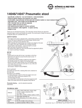
1. BESTANDTEILE
Die Halterung ist bereits komplett vormontiert.
Zunächst ist eine Sichtprüfung vorzunehmen ob, soweit
erkennbar, alle Teile vorhanden und in Ordnung sind:
a Klemmschraube M8 x 16 mm,
b Aufsteckhülse (für ø 35 mm, 75 mm tief)
c Klemmhebel mit Verschraubung
d Lagerschalen
e Schwenkhalterung mit Lochbild zur Aufnahme
e der Traglast 3.a oder einer Adapterplatte 3.b
2. MONTAGE AM STATIV
2.1 Klemmschraube a zurückdrehen bis das Gewinde
2.1 nicht mehr ins Innere der Aufsteckhülse b ragt
2.2 Aufsteckhülse bis zum Anschlag (75 mm tief) über
2.2 das Auszugrohr des Statives schieben
2.3 Stativadapter ausrichten 5 und Position durch Fest-
2.3 ziehender Klemmschraube a sichern
2.4 Klemmhebel c lösen
2.5 Schwenkhalterung e zunächst senkrecht einstellen
2.6 Diese Position durch Festziehen des Klemmhebels c
2.6 sichern. was ungewolltes Kippen der Traglast während
2.6 der Montage verhindert
3. MONTAGE DER TRAGLAST
3.a DIREKTE MONTAGE - OHNE ADAPTERPLATTE
3.a.1 Schrauben (Größe den Angaben des Lautsprecher-
3.a.1 herstellers entnehmen - nicht im Lieferumfang) bis
3.a.1 ca. 4 mm Abstand in die Gewindebuchsen an der
3.a.1 Rückwand des Lautsprechers eindrehen...
3.a.2 ...und diese dann in die Halterung e einhängen
3.a.3 Schrauben mit einem Schlüssel festziehen
3.b INDIREKTE MONTAGE - MIT ADAPTERPLATTE
3.b.1 Adapterplatte am Lautsprecher oder Bildschirm
3.b.1 festschrauben - die Schraubengröße richtet sich:
3.b.1.1 bei Lautsprechern nach den Herstellerangaben
3.b.1.1 und den Maßen der Adapter 24352-54-56-57-58-59.
3.b.1.1 Bitte besorgen Sie sich die Schrauben je nach Bedarf.
3.b.1.2 bei Bildschirmen nach den erforderlichen VESA-
3.b.1.2 Adapterplatten 19615 (■75/100) M4, 19616 (100/200)
3.b.1.2 M4 oder 19617 (■200) M6 (Schrauben sind im
3.b.1.2 Lieferumfang enthalten)
3.b.2 Sicherungsmuttern auf die Gewindebolzen der
3.b.2 Adapterplatte schrauben (ca. 4 mm Abstand halten)...
3.b.3 ...und diese dann in die Halterung e einhängen
3.b.4 Sicherungsmuttern (SW10) festziehen (10 Nm)
Vielen Dank, dass Sie sich für dieses Produkt entschieden haben. Bitte lesen und
beachten Sie vor Aufbau und Betrieb dieses Produkts sorgfältig diese Anleitung.
Sie informiert Sie über alle wichtigen Schritte um eine sichere Handhabung zu
gewährleisten. Wir empfehlen, sie auch für den späteren Gebrauch aufzubewahren.
AUFSTELLANLEITUNG
19610 Stativadapter
BESTIMMUNGSGEMÄSSER GEBRAUCH:
- Die multifunktionale Gelenkverbindung ermöglicht die Befestigung ausgewählter
- Bildschirme oder Lautsprecher auf Stativen mit ø 35 mm Auszugsrohr
MERKMALE & FÄHIGKEITEN
- max. Traglast: 25 kg (vorbehaltlich Stativeignung)
- professionelle Qualität, hervorragend verarbeitet
- Einstellmöglichkeiten: a. Ausrichtung: stufenlos drehbar um 360°
- Einstellmöglichkeiten: b. stufenlos von -30° bis +60° zur Horizontalen
- Hohe Klemmkraft durch ergonomische Klemmgriffe
- Lochbilder zur Montage der Lasten:
- 1. bei direkter Befestigung: 70 mm-M6 sowie 70 mm-M8 (3.a)
- 2. per Lautsprecher-Adapterplatten K&M-Nr. 24352 bis 24359 (3.b)
- 3. per VESA-Adapterplatten K&M-Nr. 19615, 19616, 19617 (3.b)
- Daten: Gewicht 0,9 kg, Aufstecktiefe: 75 mm für ø 35 mm
STATIVADAPTER 19610
- Max. Belastung: 25 kg, vorbehaltlich der maximalen Tragkraft des Stativs.
- Produkt einer Sichtprüfung unterziehen: beschädigte Teile dürfen nicht
- eingesetzt werden und müssen entweder ersetzt oder repariert werden.
- Nur geeignete Bildschirme oder Lautsprecher anbringen.
- Achten Sie auf: -Anschlussmaße, -Größe, -Gewicht
- Die Schraubverbindungen zwischen der Traglast, dem Stativadapter
- und etwaigen Adapterplatten müssen fest angezogen sein;
- dieser Zustand ist regelmäßig zu überprüfen.
- Die Klemmschraube zwischen Stativ und Stativadapter sowie der
- Klemmhebel zur Verstellung der Neigung müssen fest, aber nicht
- überfest angezogen werden; Handkraft genügt.
- Aufmerksame Handhabung erforderlich, da die
- Verstellmöglichkeiten Einklemmgefahren bergen
- Nur für Innenräume
- Die Sicherheitshinweise des Stativs sind zu beachten
1. BESTANDTEILE
2. MONTAGE AM
2. STATIV
3. MONTAGE DER
3. TRAGLAST
3.a DIREKTE MONTAGE - OHNE ADAPTERPLATTE
3.b INDIREKTE MONTAGE - MIT ADAPTERPLATTE
KÖNIG & MEYER GmbH & Co. KG
Kiesweg 2, 97877 Wertheim, www.k-m.de
19610-000-55 Rev.03 03-79-188-00 2/20

TECHNISCHE DATEN
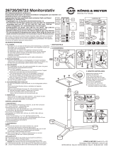
4./5. EINSTELLUNGEN
7. STANDSICHERHEIT
8. ABMESSUNGEN
4./5. EINSTELLUNGEN
4. NEIGUNG
- Schwenkbereich von -30° bis +60° zur Horizontalen.
- Bei großen oder schweren Traglasten ist es hilfreich
- mit zwei Personen zu arbeiten. Eine hält die Last,
- die andere bedient den Klemmhebel c
4.1 Zunächst sicherstellen, dass die Traglast sicher
4.1 gehalten wird
4.2 Klemmhebel c soweit lösen bis die...
4.3 ...Traglast vorsichtig geneigt werden kann
4.4 Klemmhebel wieder fest anziehen
5. AUSRICHTUNG
5.1 Klemmschraube a etwas lösen
5.2 Traglast halten und in gewünschte Richtung drehen
5.3 Klemmschraube wieder festdrehen
6. GEEIGNETE K&M-STATIVE
6.1 Grundsätzlich nur Stative mit Auszugrohr ø 35 mm
6.2 Dazu zählen aus dem K&M-Programm die Modelle:
6.2 - Boxenstative: 19500, 213, 21302, 21435, 21436,
6.2 - Boxenstative: 21449, 21450, 21455, 21460, 21463,
6.2 - Boxenstative: 21467, 26734 26735, 26750, 26737
6.2 - Leuchtenstative: 24610, 24624, 24630, 24645
6.3 Das Stativ muss aufgestellt werden gemäß der
6.3 Anleitung und den Sicherheitshinweisen
7. STANDSICHERHEIT
7.1 Die komplette INSTALLATION (= Kombination aus
7.1 Untergrund, Stativ, Stativadapter und Traglast) muss
7.1 über AUSREICHENDE STANDSICHERHEIT verfügen.
7.1 Wichtige Einflussgrößen sind:
7.1.a UNTERGRUND
7.1.a.1 - muss eben und tragfähig sein;
7.1.a.2 - schiefe Untergründe sind eine Gefahr
7.1.b STATIV
7.1.b.1 - das verwendete Stativ (Auszug ø 35 mm) muss
7.1.b.1 - in der Lage sein, das Gewicht der kompletten
7.1.b.1 - Last sicher zu tragen. Zu beachten sind:
7.1.b.2 - die angegebene maximale Stativ-Tragkraft
7.1.b.2 - (welche sich fast immer auf zentrische Lasten
7.1.b.2 - bezieht) darf nicht überschritten werden
7.1.b.3 - die Standfestigkeit des Stativs hängt ab von der
7.1.b.3 - Bauart, der Materialauswahl, dem Eigengewicht
7.1.b.3 - und dem Größenverhältnis der Fußbasis zur Höhe
7.1.b.3 - (je größer der Fußkreis, desto besser)
7.1.c TRAGLAST
7.1.c.1 - max. 25 kg seitens des Stativadapters 19610
7.1.c.2 - Ideal ist prinzipiell eine zentrische Stativbelastung,
7.1.c.2 - JEDOCH, der Stativadapter 19610 hält die Traglast
7.1.c.2 - IMMER AUSSER-ZENTRISCH
7.1.c.3 - Deshalb empfehlen wir stets, die Traglast direkt
7.1.c.3 - über einem der (je nach Stativbauart) meist
7.1.c.3 - drei Füße zu platzieren
7.1.d EXTERNE VORGABEN
7.1.d - Mögliche Seitenkräfte sind zu unterbinden
7.1.d - (Beispiele: Wind, Stöße, Herumzerren des Stativs)
7.2 5°-KIPPTEST (nach DGUV-Vorschrift 17 und 18) wird
7.2 empfohlen bei Zweifeln an der Standfestigkeit
7.2 TESTBEDINGUNGEN
7.2 Die Installation (bewusst ungünstig eingestellt, d.h. max.
7.2 Höhe, Traglast zwischen zwei Füssen) darf auf einer um
7.2 5° geneigten Ebene nicht umkippen.
7.2 WARNUNG
7.2 Bei der Durchführung dieses Tests ist die Sicherheit zu
7.2 gewährleisten: rechtzeitiges Abfangen des Stativs.
7.2 Absperrungen, Sicherungsseile etc. Ggf. Fachpersonal
7.2 hinzuziehen.
7.2 HINWEIS
7.2 Der 5°-Kipptest weist darauf hin, wie gut die Installation
7.2 Seitenkräften (Wind, Stößen) widersteht. Sein Bestehen
7.2 bedeutet NICHT, dass der Betrieb der Installation auf
7.2 einer bis zu 5° schiefen Ebene erlaubt ist. Dies gilt
7.2 vielmehr nur für ebene Untergründe.
7.3 MASSNAHMEN zur Verbesserung der Standfestigkeit sind:
7.3 - Für ebenen und tragfähigen Untergrund sorgen 7.1.a.1
7.3 - Geeignetes Stativ verwenden 7.1.b
7.3 - Traglast stets direkt über einem der Stativfüße platzieren
7.3 - Stativhöhe reduzieren
7.3 - Gewicht der Traglast reduzieren
7.3 - Basis beschweren/befestigen
7.3 - Mit Seilen abspannen
Grundsätzlich darf das Stativ nicht Gefahr laufen umzukippen
- auch bei ungünstigster Einstellung des Stativadapters 19610
BENUTZERHINWEISE
WARNUNG
Es besteht erhöhte
Kippgefahr bei der
Häufung ungünstiger
Umstände wie:
7.1.a.2
Schräger Untergrund
7.1.b
Stativ ungeeignet
7.1.c
Traglast:
- platziert zwischen
- zwei Füßen statt
- direkt über einem Fuß
- in sehr großer Höhe
- weit außer der Mitte
7.1.d
Externen Gefahren:
- Wind, - Stöße, - Zerren
MASSNAHMEN
WARTUNG
- Schonender Umgang erhält die Funktion, die Tragkraft und die
- Langlebigkeit
- Periodische Betätigung beweglicher Teile erhält deren Gängigkeit
- Wartungsarbeiten dürfen nur im unbelasteten Zustand durchgeführt
- werden
- Beschädigte Teile dürfen nicht weiterverwendet werden, sie müssen
- ersetzt bzw. repariert werden
- Schmutz, Feuchtigkeit und ggf. Korrosion sind zu entfernen
- Zur Reinigung und Pflege ein leicht feuchtes Tuch und nicht
- scheuerndes Reinigungsmittel benutze
FEHLERSUCHE (F) und BESEITIGUNG (B)
F: Stativ wackelt B: Stativ auf festen Stand hin überprüfen
B: Sind die Verschraubungen am Stativ korrekt
F: Stativ wackelt B: angezogen?
F: Stativadapter B: Sitzt die Aufsteckhülse b bis zum Anschlag auf
F: wackelt: B: dem Stativ?
B: Klemmschraube a und Klemmhebel c auf
B: Festsitz prüfen
F: Traglast wackelt: B: Passen die Anschlussmaße der Traglast zum
B: Stativadapter?
B: Die Halterung e ist für M6 und M8 geeignet,
B: deshalb: sind Traglast und ggf. Adapterplatte
B: korrekt platziert?
B: Festsitz der Verschraubung mit dem
B: Stativadapter prüfen
Material
Aufnahmehülse, Schwenkhalter, Scheiben: Stahl, gepulvert, schwarz
Gewinde, Niet: Stahl, verzinkt
Lagerschalen, Buchse, Griffe: Kunststoff (PA)
Traglast Bildschirme, Lautsprecher mit geeigneten Anschlussmaßen
Tragkraft max. 25 kg / geringere Lasten bei unsicherem Stand
Maße
Aufsteckhülse für Rohr-ø 35 mm, Halterung-Lochbild: M6/M8 x 70 mm
Außenmaß: 121 x 104 x 284 mm, Eigengewicht: 0,9 kg (brutto 1,0 kg)
Karton innen 295 x 84 x 125 mm, 0,1 kg
Kipplinie
Beispiel: Stativ K&M 214/6
(max. Belastbarkeit 50 kg)
Kippgefahr

SAFETY INSTRUCTIONS
1. COMPONENTS
The bracket is already completely pre-assembled. First of all,
a visual inspection must be carried out to determine, as far
as recognizable, all parts are present and in order:
a Clamping screw M8 x 16 mm,
b Slip-on bushing (for ø 35 mm, 75 mm deep)
c Clamping lever with screw connection
d Bearing shells
e Swivel mount with hole pattern for mounting
e the load 3.a or an adapter plate 3.b
2. MOUNTING ON THE STAND
2.1 Turn back clamping screw a until the thread no longer
2.1 protrudes into the inside of the slip-on bushing b
2.2 Slide the slip-on bushing over the extension tube
2.2 of the stand as far as it will go (75 mm deep)
2.3 Align the stand adapter 5 and secure
2.3 position by tightening the clamping screw a
2.4 Release clamping lever c
2.5 Adjust the swivel mount e vertically first
2.6 Secure this position by tightening the clamping lever c
2.6 which prevents unintentional tilting of the load during
2.6 assembly
3. MOUNTING THE LOAD
3.a DIRECT MOUNTING - WITHOUT ADAPTER PLATE
3.a.1 Turn screws (for size, refer to the specifications of the
3.a.1 speaker manufacturer - not included in the scope of
3.a.1 delivery) into the threaded sockets on the rear wall of
3.a.1 the speaker up to a distance of approx. 4 mm...
3.a.2 ...and then hook them into the bracket e
3.a.3 Tighten the screws with a spanner
3.b INDIRECT MOUNTING - WITH ADAPTER PLATE
3.b.1 Screw the adapter plate to the speaker or screen
3.b.1 - the size of the screws is determined by:
3.b.1.1 For speakers according to the manufacturer's specifi-
3.b.1.1 cations and the dimensions of the adapters 24352-
3.b.1.1 54-56-57-58-59. Please procure the screws as required
3.b.1.2 For monitors according to the required VESA adapter
3.b.1.2 plates 19615 (■75/100) M4, 19616 (100/200)
3.b.1.2 M4 or 19617 (■200) M6 (screws are included in
3.b.1.2 the scope of delivery)
3.b.2 Screw lock nuts onto the threaded bolts of the adapter
3.b.2 plate (keep a distance of approx. 4 mm)...
3.b.3 ...and then hook them into the holder e
3.b.4 Tighten the lock nuts (SW10) (10 Nm)
Thank you for choosing this product. Please read and follow these instructions carefully
before installation and use. They inform you about all important steps regarding assembly
and handling. We recommend that you keep them for future reference.
INSTALLATION INSTRUCTIONS
19610 Adapter
INTENDED USE:
- The multifunctional hinge joint allows the mounting of selected
- screens or speakers on stands with ø 35 mm extension tube
FEATURES & CAPABILITIES
- max. load capacity: 25 kg (subject to stand suitability)
- professional quality, excellent finish
- Setting options: a. Orientation: rotatable 360°.
- Setting options: b. Continuously variable from -30° to +60° to the horizontal
- High clamping force through ergonomic clamping handles
- Hole patterns for mounting the loads:
- 1. for direct mounting: 70 mm-M6 and 70 mm-M8 (3.a)
- 2. per loudspeaker adapter plates K&M-No. 24352 to 24359 (3.b)
- 3. per VESA adapter plates K&M-No. 19615, 19616, 19617 (3.b)
- Data: Weight 0.9 kg, insertion depth: 75 mm for ø 35 mm
ADAPTER 19610
- Max. load: 25 kg, subject to the maximum load capacity of the stand.
- Subject the product to a visual inspection: damaged parts must not be
- used and must either be replaced or repaired.
- Install only suitable screens or speakers. Pay attention to:
- connecting dimensions, size, weight.
- The screw connections between the load, the stand adapter and any
- adapter plates must be firmly tightened; this condition must be checked
- regularly.
- The clamping screw between stand and stand adapter and the Clamping
- levers for adjusting the inclination must be firm but not overtightened;
- manual force is sufficient.
- Careful handling is required, as the adjustment options can cause
- trapping hazards.
- For indoor use only.
- The safety instructions for the stand must be observed.
1. COMPONENTS
2. MOUNTING ON
2. THE STAND
3. MOUNTING
3. THE LOAD
3.a DIRECT MOUNTING - WITHOUT ADAPTER PLATE
3.b INDIRECT MOUNTING - WITH ADAPTER PLATE
KÖNIG & MEYER GmbH & Co. KG
Kiesweg 2, 97877 Wertheim, www.k-m.de
19610-000-55 Rev.03 03-79-188-00 2/20

TECHNICAL DATEN
4./5. SETTINGS
7. STABILITY
8. DIMENSIONS
4./5. SETTINGS
4. INCLINATION
- Swivel range from -30° to +60° to the horizontal.
- For large or heavy loads, it is helpful to work with two
persons: one person holds the load
- The other operates the clamping lever c
4.1 First make sure that the load is held securely
4.2 Release clamping lever c until the...
4.3 ...load can be tilted carefully
4.4 Tighten the clamping lever again
5. ALIGNMENT
5.1 Loosen clamping screw a slightly
5.2 Hold the load and turn it into the desired direction
5.3 Retighten the clamping screw
6. SUITABLE K&M STANDS
6.1 Basically only stands with extension tube ø 35 mm
6.2 This includes following models from the K&M range:
6.2 - Speaker stands: 19500, 213, 21302, 21435, 21436,
6.2 - Speaker stands: 21449, 21450, 21455, 21460, 21463,
6.2 - Speaker stands: 21467, 26734 26735, 26750, 26737
6.2 - Lighting stands: 24610, 24624, 24630, 24645
6.3 The stand must be set up in accordance with these
6.3 instructions and the safety instructions
7. STABILITY
7.1 The complete INSTALLATION (= combination of base,
7.1 stand, stand adapter and load capacity) must have
7.1 SUFFICIENT STAND SECURITY.
7.1 Important influencing factors are:
7.1.a UNDERGROUND
7.1.a.1 - must be level and loadbearing;
7.1.a.2 - sloping surfaces are a hazard
7.1.b STAND
7.1.b.1 - the stand used (extension ø 35 mm) must be able
7.1.b.1 - to safely support the weight of the complete load.
7.1.b.1 - Attention must be paid to the following:
7.1.b.2 - the indicated maximum load capacity of the stand
7.1.b.2 - (which almost always refers to centric loads) must
7.1.b.2 - not be exceeded
7.1.b.3 - the stability of the stand depends on the design, the
7.1.b.3 - choice of materials, the weight and the size ratio of
7.1.b.3 - the base to the height (the larger the base circle,
7.1.b.3 - the better)
7.1.c LOAD
7.1.c.1 - max. 25 kg on the side of the adapter 19610
7.1.c.2 - in principle, a centric stand load is ideal, BUT
7.1.c.2 - the 19610 adapter ALWAYS keeps the load
7.1.c.2 - OFF CENTRE
7.1.c.3 - For this reason, we always recommend placing
7.1.c.3 - the load directly above one of the usually three
7.1.c.3 - feet (depending on the type of stand)
7.1.d EXTERNAL PROVISIONS
7.1.d - Possible lateral forces must be prevented
7.1.d - (examples: wind, shocks, pulling the stand around)
7.2 5°-KIPPTEST (according to DGUV regulations 17 and 18)
7.2 is recommended if there is any doubt about the stability
7.2 TEST CONDITIONS
7.2 The installation (deliberately set unfavourably, i.e.
7.2 maximum height, load between two feet) must not
7.2 tip over on a plane inclined by 5°.
7.2 WARNING
7.2 When carrying out this test, safety must be ensured:
7.2 timely interception of the stand. Barriers, safety ropes etc.
7.2 If necessary, call in qualified personnel.
7.2 NOTE
7.2 The 5° tilt test indicates how well the installation
7.2 resists lateral forces (wind, shocks). Its existence
7.2 does NOTmean that the installation is allowed to
7.2 operate on an incline of up to 5°. Rather, this only
7.2 applies to flat surfaces.
7.3 MEASURES to improve stability:
7.3 - Ensure a level and stable base 7.1.a.1
7.3 - Use a suitable stand 7.1.b
7.3 - Always place the load directly above one
7.3 - of the stand feet
7.3 - Reduce stand height
7.3 - Reduce the weight of the load
7.3 - Weigh down/fix the base
7.3 - Fix with tensioning ropes
Basically, the stand should not risk tipping over - even if the
stand adapter 19610 has the most adverse setting
USER INSTRUCTIONS
WARNING
There is an increased
tipping risk when unfa-
vourable circumstances
such as accumulate:
7.1.a.2
sloping floor
7.1.b
unsuitable stand
7.1.c
Load:
- placed between two
- feet instead directly
- above one foot
- at very high altitude
- far from the centre
7.1.d
External hazards:
- wind, - percussion,
- tugging
MEASURES
MAINTENANCE
- Gentle handling preserves the function, the load capacity
- and the longevity
- Periodic actuation of moving parts maintains their mobility
- Maintenance work should only be carried out in an unloaded
- condition
- Damaged parts must not be reused, they must be replaced
- or repaired
- Dirt, moisture and any corrosion must be removed
- Use a slightly damp cloth and non-abrasive cleaning agent
- for cleaning and care.
FAULT-FINDING (F) and REPAIR (R)
F: Stand wobbles R: Check stand for stability
R: Are the screw connections on the stand
F: Stativ wackelt R: tightened correctly?
F: Stand adapter R: Is the sleeve b seated on the stand as far
F: wobbles: R: as it will go?
R: Check clamping screw a and
R: clamping lever c for tightness
F: Load wobbles: R: Do the connection dimensions of the load
R: capacity match the stand adapter?
R: The bracket e is suitable for M6 and M8,
R: check if: load and, if necessary, the adapter
R: plate are correctly positioned?
R: Check the tightness of the screw connection
R: with the stand adapter
Material
Receptive sleeve, swivel holder, discs: steel, powdered, black
Thread, rivet: galvanised steel
Bearing shells, bushing, handles: plastic (PA)
Load Screens, loudspeakers with suitable connection dimensions
Load capacity max. 25 kg / lower loads when stand is insecure
Dimensions
Slip-on sleeve for tube-ø 35 mm, mounting hole pattern: M6/M8 x 70 mm
Outer dimensions: 121 x 104 x 284 mm, net weight: 0.9 kg (gross 1.0)
Carton inside 295 x 84 x 125 mm, 0.1 kg
tipping line
Example: Stand K&M 214/6
(max. load capacity 50 kg)
risk of tipping
1/4