
Multiband-Verstärker
Multiband Amplifier
PAS 152/551 N/DVB-T
Bedienungsanleitung/
Operating manual
0901019

HINWEIS
Der Inhalt dieses Firmenhandbuches ist urheber-
rechtlich geschützt und darf ohne Genehmigung
des Erstellers weder ganz noch teilweise in
irgendeiner Form vervielfältigt oder kopiert wer-
den. Änderungen in diesem Firmenhandbuch,
die ohne Zustimmung des Erstellers erfolgen,
können zum Verlust der Gewährleistung bzw.
zur Ablehnung der Produkthaftung seitens des
Herstellers führen. Für Verbesserungsvorschlä-
ge ist der Ersteller dankbar.
Ersteller:
Polytron-Vertrieb GmbH
Postfach 10 02 33
75313 Bad Wildbad
Germany
Unten stehende Hervorhebungen werden in
diesem Handbuch mit folgenden Bedeutungen
verwendet:
HINWEIS gilt für technische Erfordernisse,
die der Benutzer der Geräte be-
sonders beachten muss, um ei-
ne einwandfreie Funktion der
Geräte/Anlage zu gewährleisten.
ACHTUNG bezieht sich auf Anweisungen,
die genau einzuhalten sind, um
eine Beschädigung oder Zerstö-
rung des Gerätes zu vermeiden.
VORSICHT steht für Anweisungen, deren
Nichtbeachtung eine Gefährdung
von Personen nicht ausschließt.
Bei Hinweisen auf ein durch eine Ortszahl ver-
sehenes Bauteil z.B. (Bild 1/3) bezieht sich in
diesem Beispiel der Hinweis auf Bild 1 Ortszahl
3.
NOTE
The contents of this company manual are copy-
righted and must not be duplicated or copied in
any form, either partially or in full, without the
prior consent of the creator. Changes in this
company manual which are carried out without
consent of the creator can lead to the loss of the
guarantee or to the rejection of the product
liability on the part of the manufacturer. The
creator is grateful for suggestions for improve-
ment.
Creator:
Polytron-Vertrieb GmbH
Postfach 10 02 33
75313 Bad Wildbad
Germany
The following emphases are used in this manual
with the following meanings:
NOTE apply to technical requirements which
the user of the equipment must par-
ticularly take into account to ensure a
faultless function of the equip-
ment/plant.
ATTENTION refers to instructions which have
to be adhered exactly to avoid
damage or destruction of the de-
vice.
CAUTION stand for instructions whose nonob-
servance doesn't exclude the
endangering of persons.
At references to a component e.g. (figure 1/3)
provided by a place number the reference to
picture 1 place number 3 refers in this example

Sicherheitshinweise
Vor Inbetriebnahme des Gerätes bitte unbe-
dingt folgende Sicherheitsbestimmungen
lesen!
Wichtig: Das Öffnen des Gerätes sollte nur
von Fachpersonal durchgeführt werden. Vor
Beginn der Servicearbeiten das Gerät von der
Spannungsversorgung trennen, da beim
Öffnen des Gehäuses spannungsführende
Teile freigelegt werden, die bei Berührung
lebensgefährlich sein können. Um die Stör-
strahlsicherheit des Verstärkers zu garantie-
ren, muss der Verstärkerdeckel nach dem
Öffnen wieder fest verschraubt werden!
Umgebungstemperatur Die Umgebungs-
temperatur darf den Bereich von 0 °C bis +50
°C nicht überschreiten.
Feuchtigkeit Das Gerät darf nicht Tropf- oder
Spritzwasser ausgesetzt werden. Bei Kon-
denswasserbildung unbedingt warten, bis das
Gerät wieder trocken ist.
Netzanschluss und Netzkabel
Bei Geräten mit der Netzteil-Schutzklasse I
muss der gelb/grüne Leiter mit dem Stecker-
anschluss "E" oder
verbunden werden.
Der blaue Leiter muss mit dem Anschluss "N"
und der braune Leiter mit dem Anschluss "L"
verbunden werden. Geräte die mit einer
Fernspeise-Stromversorgung arbeiten, dürfen
auf keinen Fall an 230 V~ angeschlossen
werden, sonst besteht Lebensgefahr!
Bei Geräten mit der Netzteil-Schutzklasse II
muss das Gehäuse des Gerätes an der in der
Bedienungsanleitung angegebenen Stelle
geerdet werden. Der Schutzleiter ist in diesem
Fall nicht angeschlossen.
Erdung der Anlage
Nach den EN 50 083 / VDE 0855 Bestim-
mungen muss die Antennenanlage den Si-
cherheitsbestimmungen wie z.B. Erdung,
Potenzialausgleich, etc. entsprechen.
Bedingungen zur Sicherstellung der
elektromagnetischen Verträglichkeit (EMV)
Alle Abdeckungen und Schrauben müssen
fest montiert und angezogen sein, Kontaktfe-
dern dürfen nicht oxidiert oder verbogen sein.
Safety instructions
Before taking the unit into operation please
read the following safety precautions careful-
ly!
Important: The unit should only be opened
by qualified persons. The unit must be dis-
connected from its power supply before ser-
vice work is carried out. When the unit is open
parts may be accessible through which dan-
gerous voltages flow and with which contact
may endanger your life. To guarantee the
EMC protection of the amplifier the lid must
be bold tight again after opening the amplifier.
Ambient temperature The ambient tempera-
ture should not exceed a range of 0 °C to
+50 °C (32 °F to 122 °F).
Humidity The unit may not be exposed to
water drops or spray. If condensation is pre-
sent, wait until the unit is dry before taking it
into operation.
Mains connection and mains cable
By units with the power supply safety class I,
the wire which is coloured green/yellow must
be connected to the terminal in the plug
marked with the letter "E" or by the earth
symbol . The blue coloured wire must be
connected to the terminal marked "N" and the
brown coloured wire to the terminal marked
"L". Units which operate with a remote feeding
supply may not be connected to 230 VAC. To
do so will endanger your life! At units with the
power supply safety class II, the housing of
the unit must be connected to ground at the
place indicated in the operating instructions of
the unit. The ground terminal of the plug is in
the case not connected.
Grounding of system
According to EN 50 083 / VDE 0855 regula-
tions, the antenna system must comply with
the safety regulations e.g. grounding, poten-
tial equilization etc.
Precautions to ensure the electro magnet-
ic compability (EMV)
All covers and screws must tightly be fitted
and should be tightly fastened. Contact
feathers should not be oxidated or deformed.

1 Beschreibung
Der PAS-Verstärker ist ein Multi-
band-Verstärker für analoge und
digitale (DVB-T) terrestrische Signa-
le. Er hat fünf Eingänge und einen
Ausgang. Die Eingangspegel der
fünf Eingänge lassen sich über ein-
gebaute 20-dB-Dämpfungsregler
(Bild 4/8) justieren. Die möglichen
Einstellungen (Frequenzbereiche
und Dämpfung) sind auf der Gehäu-
sedeckel-Innenseite (Bild 2) abge-
bildet.
Das großzügig bemessene Netzteil
garantiert eine lange Lebensdauer.
Eine grüne Leuchtdiode zeigt die
Betriebsspannung an.
Das neue Gehäusekonzept ent-
spricht der Schutzklasse IP 65.
1 Description
The PAS amplifier is a multiband
amplifier for analogue and digital
(DVB-T) terrestrial signals. It has five
inputs and one output. The input
levels of the five inputs can be ad-
justed about built-in 20 dB variable
attenuators (Figure 4/8). The possi-
ble settings (frequency ranges and
attenuation) are shown in the inside
of the case top (Figure 2).
The power supply guarantees a long
life cycle. A green light-emitting di-
ode shows the operating voltage.
The new housing conforms to the
protection class IP 65.

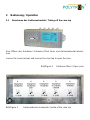
2 Bedienung / Operation
2.1 Abnehmen des Gehäuseoberteils / Taking off the case top
Zum Öffnen des Gehäuses Schraube (Pfeil) lösen und Gehäuseoberteil abneh-
men.
Loosen the screw (arrow) and remove the case top to open the case.
Bild/Figure 1 Gehäuse öffnen / Open case
Bild/Figure 2 Gehäusedeckel-Innenseite / inside of the case top

3 Technische Daten / Technical data
Type PAS 152/551 N/DVB-T
Artikel-Nr / Article no. 1135510
Eingang
Input
Bd4/5 Bd4/5 Bd3 Bd2 Bd1
Frequenzbereich
Frequency range
470 … 862
MHz
470 … 862
MHz
DVB-T
174 … 230
MHz
87,5 … 108
MHz
UKW/FM
47 … 68
MHz
Verstärkung
Amplification
50 dB 44 dB 38 dB 38 dB 38 dB
Pegelsteller
Variable attenuator
0 … 20 dB 0 … 20 dB 0 … 20 dB 0 … 20 dB 0 … 20 dB
Rauschmaß
Noise figure
analog 10 dB
digital 7 dB
6 dB 6 dB 6 dB
Rückflussdämpfung
Return loss
typ. 10 dB
Ausgangspegel 60 dB IMA
3
Output level 60 dB IMA
3
120 dBµV
Spannungsversorgung
Power supply
230 V~ / 7 W
Zulassung
Certification
4 Blockschaltbild / Functional block diagram
Bild/Figure 3 PAS 152/551 N/DVB-T

5 Bauteile des Ter.-Multiband-Verstärkers
Components of the Ter.-Multiband Amplifier
1 Netzteil 6 Bd1-Signaleingang
Power Supply Bd1-Signal input
2 Bd4/5-Signaleingang (UHF1) 7 Signalausgang
Bd4/5-Signal input (UHF1) Signal output
3 Bd4/5-Signaleingang (DVB-T-UHF2) 8 Pegelsteller
Bd4/5-Signal input (DVB-T-UHF2) Variable attenuator
4 Bd3-Signaleingang 9 Netzanschluss
Bd3-Signal input Mains connection
5 Bd2-Signaleingang
Bd2-Signal input
Bild/Figure 4 Bauteile des Ter.-Multiband-Verstärkers
Components of the Ter.-Multiband Amplifier
7
9
1
2
6
3
4
5
8

Polytron-Vertrieb GmbH
Postfach 10 02 33
75313 Bad Wildbad
Zentrale/Bestellannahme
H.Q. Order department + 49 (0) 70 81/1702 - 0
Technische Hotline
Technical hotline + 49 (0) 70 81/1702 - 12
Telefax + 49 (0) 70 81) 1702 - 50
Internet http://www.polytron.de
eMail [email protected]
Technische Änderungen vorbehalten
Subject to change without prior notice
Copyright © Polytron-Vertrieb GmbH
-
 1
1
-
 2
2
-
 3
3
-
 4
4
-
 5
5
-
 6
6
-
 7
7
-
 8
8


POLYTRON PAS 152/551 N Selective range amplifier 40/50dB Bedienungsanleitung
- Typ
- Bedienungsanleitung
- Dieses Handbuch eignet sich auch für
in anderen Sprachen
Verwandte Artikel
-
POLYTRON PAS 28113 N Selective range amplifier 28dB F connector Bedienungsanleitung
-
-
-
-
-
-
-
-
-