
1
Hausanschlussverstärker
Home Distribution Amplifier
HA 20114 N/F A/P
HA 30114 N/F A/P
Bedienungsanleitung/
Operating manual
0900946 V.2

HINWEIS
Der Inhalt dieses Firmenhandbuches ist urheber-
rechtlich geschützt und darf ohne Genehmigung
des Erstellers weder ganz noch teilweise in ir-
gendeiner Form vervielfältigt oder kopiert wer-
den. Änderungen in diesem Firmenhandbuch,
die ohne Zustimmung des Erstellers erfolgen,
können zum Verlust der Gewährleistung bzw.
zur Ablehnung der Produkthaftung seitens des
Herstellers führen. Für Verbesserungsvorschlä-
ge ist der Ersteller dankbar.
Ersteller:
Polytron-Vertrieb GmbH
Postfach 10 02 33
75313 Bad Wildbad
Germany
Unten stehende Hervorhebungen werden in die-
sem Handbuch mit folgenden Bedeutungen ver-
wendet:
HINWEIS gilt für technische Erfordernisse,
die der Benutzer der Geräte be-
sonders beachten muss, um ei-
ne einwandfreie Funktion der
Geräte/Anlage zu gewährleisten.
ACHTUNG bezieht sich auf Anweisungen,
die genau einzuhalten sind, um
eine Beschädigung oder Zerstö-
rung des Gerätes zu vermeiden.
VORSICHT steht für Anweisungen, deren
Nichtbeachtung eine Gefährdung
von Personen nicht ausschließt.
Bei Hinweisen auf ein durch eine Ortszahl ver-
sehenes Bauteil z.B. (Bild 1/3) bezieht sich in
diesem Beispiel der Hinweis auf Bild 1 Ortszahl
3.
NOTE
The contents of this company manual are copy-
righted and must not be duplicated or copied in
any form, either partially or in full, without the
prior consent of the creator. Changes in this
company manual which are carried out without
consent of the creator can lead to the loss of the
guarantee or to the rejection of the product liabil-
ity on the part of the manufacturer. The creator is
grateful for suggestions for improvement.
Creator:
Polytron-Vertrieb GmbH
Postfach 10 02 33
75313 Bad Wildbad
Germany
The following emphases are used in this manual
with the following meanings:
NOTE apply to technical requirements which
the user of the equipment must par-
ticularly take into account to ensure a
faultless function of the equip-
ment/plant.
ATTENTION refers to instructions which have
to be adhered exactly to avoid
damage or destruction of the de-
vice.
CAUTION stand for instructions whose nonob-
servance doesn't exclude the
endangering of persons.
At references to a component e.g. (figure 1/3)
provided by a place number the reference to pic-
ture 1 place number 3 refers in this example.

Sicherheitshinweise
Vor Inbetriebnahme des Gerätes bitte unbedingt
folgende Sicherheitsbestimmungen lesen!
Umgebungstemperatur Die Umgebungstempe-
ratur darf den Bereich von 0 °C bis +50 °C nicht
überschreiten.
Feuchtigkeit Das Gerät darf nicht Tropf- oder
Spritzwasser ausgesetzt werden. Bei Kondens-
wasserbildung unbedingt warten, bis das Gerät
wieder trocken ist.
Netzanschluss und Netzkabel
Bei Geräten mit der Netzteil-Schutzklasse I muss
der gelb/grüne Leiter mit dem Steckeranschluss
"E" oder
verbunden werden. Der blaue Leiter
muss mit dem Anschluss "N" und der braune Lei-
ter mit dem Anschluss "L" verbunden werden.
Geräte die mit einer Fernspeise-
Stromversorgung arbeiten, dürfen auf keinen Fall
an 230 V~ angeschlossen werden, sonst besteht
Lebensgefahr!
Bei Geräten mit der Netzteil-Schutzklasse II
muss das Gehäuse des Gerätes an der in der
Bedienungsanleitung angegebenen Stelle geer-
det werden. Der Schutzleiter ist in diesem Fall
nicht angeschlossen.
Erdung der Anlage
Nach den EN 50 083 / VDE 0855 Bestimmungen
muss die Antennenanlage den Sicherheitsbe-
stimmungen wie z.B. Erdung, Potenzialaus-
gleich, etc. entsprechen.
Bedingungen zur Sicherstellung der
elektromagnetischen Verträglichkeit (EMV)
Alle Abdeckungen und Schrauben müssen fest
montiert und angezogen sein, Kontaktfedern dür-
fen nicht oxidiert oder verbogen sein.
Safety instructions
Before taking the unit into operation please read
the following safety precautions carefully!
Ambient temperature The ambient temperature
should not exceed a range of 0 °C to +50 °C
(32 °F to 122 °F).
Humidity The unit may not be exposed to water
drops or spray. If condensation is present, wait
until the unit is dry before taking it into operation.
Mains connection and mains cable
By units with the power supply safety class I, the
wire which is coloured green/yellow must be
connected to the terminal in the plug marked
with the letter "E" or by the earth symbol . The
blue coloured wire must be connected to the
terminal marked "N" and the brown coloured wire
to the terminal marked "L". Units which operate
with a remote feeding supply may not be con-
nected to 230 VAC. To do so will endanger your
life! At units with the power supply safety class II,
the housing of the unit must be connected to
ground at the place indicated in the operating in-
structions of the unit. The ground terminal of the
plug is in the case not connected.
Grounding of system
According to EN 50 083 / VDE 0855 regulations,
the antenna system must comply with the safety
regulations e.g. grounding, potential equilization
etc.
Precautions to ensure the electro magnetic
compability (EMV)
All covers and screws must tightly be fitted and
should be tightly fastened. Contact feathers
should not be oxidated or deformed.

1 Beschreibung
Die Hausanschlussverstärker
HA 20114... und HA30114... sind
insbesonders für den Einsatz in
Ein- , Zwei- oder kleineren Mehr-
familienhäusern ausgelegt.
Die Varianten mit dem aktivem
Rückkanal unterstützen Mehr-
zweckdienste in Kabelnetzen.
Eine Leuchtdiode zeigt die
Betriebsspannung an und der re-
gelbare Pegelsteller sorgt für den
richtigen Ausgangspegel.
1 Description
The home distribution amplifiers
HA 20114... and HA30114... are
particularly suitable for one, two or
smaller more family houses.
The versions with an active return
channel are prepared for the multi-
purpose services in C.A.T.V. sys-
tems.
A LED shows the operating voltage
and a variable equalizer ensures
the right output level.
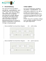
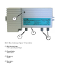
Blockschaltbild/ Functional block diagram
HA ….aktiv/ aktive
Blockschaltbild/ Functional block diagram
HA ….passiv/ passive

Bild 1 Beschreibung / figure 1 Description
(1) Betriebsanzeige
LED operating voltage
(2) Pegelsteller
Attenuator
(3) Eingang
Input
(4) Ausgang
Output
1
2
3
4
4

2 Inbetriebnahme
1. Montage
Gerät an seinen Bestimmungsort
mit den beiliegenden Schrauben
befestigen
2. Pegelsteller
Den Ausgangspegel des Verstär-
kers mit dem Pegelsteller ( Bild1/2)
einstellen.
2 Commissioning
1. Mounting
Attach the amplifier to its destina-
tion with the enclosed screws.
2. Attenuator
Adjust the output level of the ampli-
fier by the attenuator.
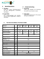
3 Technische Daten/ Technical d
a
ta
Typ/Type
HA 20114 N/
P30
HA 20114 N/
P65
HA 30114 N/
P30
HA 30114 N/
P65
Ausgänge/
Outputs
1
Frequenzbereich/
Frequency range
MHz 47-862 86-862 47-862 86-862
Passiver Rückkanal/
Passive returnpath
MHz 4-30 4-65 4-30 4-65
Verstärkung/Gain dB 20
24-30
( Pre-equalisation 6/ Vorentzerrung 6)
Pegelsteller/
Variable attenuator
dB -10
Ausgang/
Output level dBµV
MHz 862
60 dB IMR3 (DIN 45004B) dBµV
114
60 dB IMR2 (DIN 45004A1) dBµV
104
60 dB CTBA dBµV
98
60 dB CSO dBµV
97
Rauschmaß/
Noise figure
dB <= 5
Spannungsversorgung/
Power Supply
V~ 230
Leistungsaufnahme/
Power consumption
W 4,0 4,5
Maße/ Dimensions mm 140 x 70 x 36
Weight kg 0,72

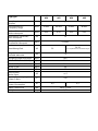
Typ/Type
HA 20114 N/
A30
HA 20114 N/
A65
HA 30114 N/
A30
HA 30114 N/
A65
Ausgänge/
Outputs
1
Frequenzbereich/
Frequency range
MHz 47-862 86-862 47-862 86-862
Aktiver Rückkanal/
Aktive returnpath
MHz 4-30 4-65 4-30 4-65
Verstärkung Rückkanal/
Gain returnpath
dB 10
Ausgangspegel Rückkanal/
Outputlevel returnpath
dBµV
114 max.
Verstärkung/Gain dB 20
24-30
( Pre-equalisation 6/ Vorentzerrung 6)
Pegelsteller/
Variable attenuator
dB -10
Ausgang/Output level dBµV MHz 862
60 dB IMR3 (DIN 45004B) dBµV
114
60 dB IMR2 (DIN 45004A1) dBµV
104
60 dB CTBA dBµV
98
60 dB CSO dBµV
97
Rauschmaß/
Noise figure
dB <= 5
Spannungsversorgung/
Power Supply
V~ 230
Leistungsaufnahme/
Power consumption
W 4,0 4,5
Maße/ Dimensions mm 140 x 70 x 36
Weight kg 0,72

Polytron-Vertrieb GmbH
Postfach 10 02 33
75313 Bad Wildbad
Zentrale/Bestellannahme
H.Q. Order department + 49 (0) 70 81/1702 - 0
Technische Hotline
Technical hotline + 49 (0) 70 81/1702 - 12
Telefax + 49 (0) 70 81) 1702 - 50
Internet http://www.polytron.de
eMail info@polytron.de
Technische Änderungen vorbehalten
Subject to change without prior notice
Copyright © Polytron-Vertrieb GmbH
-
 1
1
-
 2
2
-
 3
3
-
 4
4
-
 5
5
-
 6
6
-
 7
7
-
 8
8


POLYTRON HA 20114 Home distribution amplifier 20 dB Bedienungsanleitung
- Typ
- Bedienungsanleitung
- Dieses Handbuch eignet sich auch für
in anderen Sprachen
Verwandte Artikel
-
POLYTRON HC 20/30115 RS Home distribution amplifier 20/30 dB Bedienungsanleitung
-
-
-
-
-
-
-
-
POLYTRON HV 18 Distribution amplifier 18 dB Bedienungsanleitung
-