
1
BK-Hausanschlussverstärker
CATV-Home Distribution Amplifier
HA 40125 N / AP
Bedienungsanleitung/
Operating manual
0901014 V8

2
HINWEIS
Der Inhalt dieses Firmenhandbuches ist urheber-
rechtlich geschützt und darf ohne Genehmigung
des Erstellers weder ganz noch teilweise in ir-
gendeiner Form vervielfältigt oder kopiert werden.
Änderungen in diesem Firmenhandbuch, die ohne
Zustimmung des Erstellers erfolgen, können zum
Verlust der Gewährleistung bzw. zur Ablehnung
der Produkthaftung seitens des Herstellers führen.
Für Verbesserungsvorschläge ist der Ersteller
dankbar.
Ersteller:
Polytron-Vertrieb GmbH
Postfach 10 02 33
75313 Bad Wildbad
Germany
Unten stehende Hervorhebungen werden in
diesem Handbuch mit folgenden Bedeutungen
verwendet:
HINWEIS gilt für technische Erfordernisse,
die der Benutzer der Geräte be-
sonders beachten muss, um eine
einwandfreie Funktion der Gerä-
te/Anlage zu gewährleisten.
ACHTUNG bezieht sich auf Anweisungen, die
genau einzuhalten sind, um eine
Beschädigung oder Zerstörung
des Gerätes zu vermeiden.
VORSICHT steht für Anweisungen, deren
Nichtbeachtung eine Gefährdung
von Personen nicht ausschließt.
Bei Hinweisen auf ein durch eine Ortszahl verse-
henes Bauteil z.B. (Bild 1/3) bezieht sich in die-
sem Beispiel der Hinweis auf Bild 1 Ortszahl 3.
NOTE
The contents of this company manual are copy-
righted and must not be duplicated or copied in
any form, either partially or in full, without the prior
consent of the creator. Changes in this company
manual which are carried out without consent of
the creator can lead to the loss of the guarantee
or to the rejection of the product liability on the
part of the manufacturer. The creator is grateful
for suggestions for improvement.
Creator:
Polytron-Vertrieb GmbH
Postfach 10 02 33
75313 Bad Wildbad
Germany
The following emphases are used in this manual
with the following meanings:
NOTE applies to technical requirements
which the user of the equipment
must particularly take into account
to ensure a faultless function of
the equipment/plant.
ATTENTION refers to instructions which have to
be adhered exactly to avoid dam-
age or destruction of the device.
CAUTION stands for instructions whose
nonobservance doesn't exclude
the endangering of persons.
At references to a component e.g. (figure 1/3)
provided by a place number the reference to
picture 1 place number 3 refers in this example.

3
Inhaltsverzeichnis / Table of contents
Deutsch
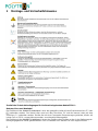
1 Montage- und Sicherheitshinweise / Mounting and safety instructions .. 4/5
2 Beschreibung / Description ......................................................................... 6
2.1 BK-Hausanschlussverstärker / CATV home distribution amplifiers ........... 6
2.2 Rückkanalmodul / Return path module ...................................................... 6
3 Bedienung / Operation ................................................................................ 7
3.1 Abnehmen des Gehäuseoberteils / Remove case to ................................ 7
3.2 Einbau eines Rückkanalmoduls / Installation of a return path module ...... 8
3.3 Pegelreduzierung / level reduction… ......................................................... 9
3.4 Steckbrücken / Set point bridges ............................................................. 10
3.5 Verschließen des Gehäuses / Closing case top ...................................... 10
4 Technische Daten / Technical data .......................................................... 11
4.1 BK-Hausanschlussverstärker / CATV-Home-Distribution-Amplifier ........ 11
4.2 Rückkanalmodul / Return path module .................................................... 12
5 Blockschaltbild / Functional block diagram ............................................... 13
6 Bauteile der BK-Hausanschlussverstärker / Components of the CATV-
Home-Distribution-Amplifier ...................................................................... 14

4
1 Montage- und Sicherheitshinweise
Zusätzliche Sicherheitsbedingungen für Geräte mit eingebautem Netzteil 230 V~
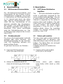
Netzanschluss und Netzkabel
Bei Geräten mit der Netzteil-Schutzklasse I muss der gelb/grüne Leiter mit dem Steckeranschluss "E" oder
verbunden werden. Der blaue Leiter muss mit dem Anschluss "N" und der braune Leiter mit dem
Anschluss "L" verbunden werden. Geräte die mit einer Fernspeise-Stromversorgung arbeiten, dürfen auf
keinen Fall an 230 V~ angeschlossen werden, sonst besteht Lebensgefahr!
Bei Geräten mit der Netzteil-Schutzklasse II muss das Gehäuse des Gerätes an der in der Bedienungsan-
leitung angegebenen Stelle geerdet werden. Der Schutzleiter ist in diesem Fall nicht angeschlossen.

5
1 Mounting and safety instructions
Additional safety precautions for units with a built-in power supply 230 V AC
Mains connection and mains cable
By units with the power supply safety class I, the wire which is coloured green/yellow must be connect-
ed to the terminal in the plug marked with the letter "E" or by the earth symbol . The blue coloured wire
must be connected to the terminal marked "N" and the brown coloured wire to the terminal marked "L".
Units which operate with a remote feeding supply may not be connected to 230 VAC. To do so will endan-
ger your life!
By units with the power supply safety class II, the housing of the unit must be connected to ground at
the place indicated in the operating instructions of the unit. The ground terminal of the plug is in the case
not connected.

6
2 Beschreibung
2.1 BK-Hausanschlussverstärker
Die HA-Hausanschlussverstärker sind
insbesondere für den Einsatz in Mehr-
familienhäusern ausgelegt. Der Einsatz
in Kabelnetzen mit Mehrzweckdiensten
(z. B. Internet) wird durch das aktive
oder passive Rückkanalmodul unter-
stützt. Mit den Steckbrücken ist ein
genaues einstellen des Ausgangspe-
gels möglich. Das großzügig bemesse-
ne Netzteil garantiert eine lange Le-
bensdauer. Eine grüne Leuchtdiode
zeigt die Betriebsspannung an. Das
Gehäusekonzept entspricht der Schutz-
klasse IP65.
2.2 Rückkanalmodul
Die neuen Rückkanalmodule (optional)
verfügen über einen Entzerrer- und
Dämpfungssteckplatz für die Steckbrü-
cken. Die Duplexfilter befinden sich
direkt auf dem Modul.
Es gibt zwei Versionen von Modulen:
1) Passives Rückkanalmodul
RPM 0/30 oder RPM 0/65
2) Aktives Rückkanalmodul RPM
20/65, RPM 30/30 oder RPM 30/65
2 Description
2.1 CATV-Home-Distribution-
Amplifiers
The HA-home-distribution-amplifiers
series is particularly designed for the
use in multiple family dwellings. The use
in cable networks with multimedia (e.g.
Internet) is supported by the active or
passive return path modules. The right
output level can be exactly adjusted by
set point bridges. The power supply
guarantees a long life cycle. A light-
emitting diode shows the operating
voltage. The housing conforms to the
protection class IP65.
2.2 Return path modules
The new return path modules (optional)
are equipped with an equalizer- and
attenuator-plug-in place for the set point
bridges. The diplex filters are arranged
directly on the module.
Following versions of modules are
available:
1) Passive return path module
RPM 0/30 or RPM 0/65
2) Active return path module
RPM 20/65, RPM 30/30 or RPM
30/65

7
3 Bedienung
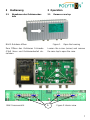
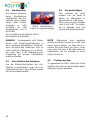
3.1 Abnehmen des Gehäuseober-
teils
Bild 1 Gehäuse öffnen
Zum Öffnen des Gehäuses Schraube
(Pfeil) lösen und Gehäuseoberteil ab-
nehmen.
3 Operation
3.1 Remove case top
Figure 1 Open the housing
Loosen the screw (arrow) and remove
the case top to open the case.
1
Bild 2 Innenansicht
Bild 2 Innenansicht
Figure 2 Interior view

8
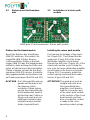
3.2 Einbau eines Rückkanalmo-
duls
Einbau des Rückkanalmoduls
Zuerst die Brücken des Verstärkers
(Bild 2/1) entfernen. Die beiden Füh-
rungsstifte (Bild 2/2) der Hausan-
schlussverstärker-Platine in die Boh-
rungen (Bild 3/1) des Rückkanalmoduls
einfädeln, diese entlang der Stifte nach
unten auf die Hausanschlussverstärker-
Platine schieben und auf die drei Buch-
senreihen (Bild 2/3) stecken. Kontaktfe-
dern gegebenenfalls nachjustieren und
auf Spannung biegen (Bild 2/4 und 3/2).
ACHTUNG Die Führungsstifte müssen
gerade und senkrecht auf
der Hausanschluss-
verstärker-Platine stehen,
um die Anschlussstifte des
Rückkanalmoduls exakt in
die Buchsen der Platine zu
führen und somit auch ein
leitfähiger Kontakt zu den
entsprechenden Kontakt
federn hergestellt wird.
3.2 Installation of a return path
module
Installing the return path module
First remove the bridges of the ampli-
fier (Figure 2/1). Then thread the two
guide pins (Figure 2/2) of the home-
distribution-amplifier circuit board
through the drill holes (Figure 3/1) of the
return path module, push it along the
pins onto the home-distribution-amplifier
circuit board on the three socket rows
(Figure 2/3). If necessary, adjust the
contact springs and keep them under
tension (Figure 2/4 and 3/2).
ATTENTION The guide pins must be
straight and vertical on
the home-distribution-
amplifier circuit board to
lead the connection pins
of the return path module
to the sockets of the circuit
board exactly and thus
also a conductive contact
is made to the corre-
sponding contact springs.
Bild/Figure 3 Rückkanalmodul / Return path module

9
3.3 Pegelreduzierung
HA 40125 N/AP
Bitte folgendes beachten:
Beim Anschließen des Verstärkers
ist der zulässige Ausgangspegel zu
beachten.
Der Verstärker wird mit zugedreh-
tem Dämpfungsregler (-20 dB) aus-
geliefert.
Beim Einstellen des Gerätes auf die
gewünschte Verstärkung, ist die üb-
liche Tabelle (siehe unten) zur Pe-
gelreduzierung in Abhängigkeit der
Anzahl der Kanäle zu berücksichti-
gen.
Bei Nichtbeachtung kann das Gerät
beschädigt werden.
3.3 Level reduction
HA 40125 N/AP
Please note the following:
When connecting the amplifier,
please pay attention to the max.
permissible output level.
The variable attenuator is turned to
max. attenuation (-20 dB) upon
leaving the factory.
When setting the amplifier to the
required amplification, the usual
table (see below) for level reduction
in relation to the number of chan-
nels must be taken into considera-
tion.
Please note that an excessive pow-
er level can damage the amplifier.
Anzahl der belegten Kanäle Pegelreduzierung in dB
No. of occupied channels Level reduction in dB
2 -0
3 -2
4 -3
5 -4
6 -5
7 -5,5
8 -6
10 -7
12 -8
16 -9
24 -11
36 -12,5

10
3.4 Steckbrücken
Die optional verwend-
baren Steckbrücken
ermöglichen die Ein-
stellung eines Dämp-
fungs- oder Entzer-
rerwertes in 1-dB-
Schritten. Es gibt
Steckbrücken von 0
bis 20 dB.
Der Verstärker wird ab Werk mit Po-
tentiometern ausgeliefert.
HINWEIS Vorzugsweise sind Dämp-
fungs- und Entzerrereinstellungen in
den Interstage-Steckplätzen vorzuneh-
men, da diese das Rauschen nicht so
stark erhöhen. Allerdings ist zu beach-
ten, dass max. 6 dB Dämpfung oder
Entzerrung auf diesen Steckplätzen
realisiert werden.
3.5 Verschließen des Gehäuses
Um die Störstrahlsicherheit des Ver-
stärkers zu garantieren, muss der Ver-
stärkerdeckel nach dem Öffnen wieder
fest verschraubt werden!
3.4 Set point bridges
The optional set point
bridges can be used to
adjust an attenuation or
equalization in 1-dB-steps.
There are set point bridges
from 0 to 20 dB. The ampli-
fier is shipped from the
factory with potentiometers.
NOTE Attenuation and equalizer
setting should be carried out in the inter
stage plug-in places, as they don't in-
crease the noise there too much. How-
ever, note that max. 6 dB attenuation or
equalization can be realized on these
plug-in locations.
.
3.5 Closing case top
To guarantee the EMC protection of the
amplifier the lid must be bold tight again
after opening the amplifier.
Bild 4 Steckbrücken
Figure 4 Set point bridges

11
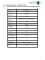
4 Technische Daten / Technical data
4.1 BK-Hausanschlussverstärker / CATV-Home-Distribution-Amplifier
Type
HA 40125 N/AP
Frequenzbereich
Frequency range
4 - 862 MHz
Rückkanalfrequenz
Return path
frequency range
30 / 65 MHz
Verstärkung
Gain
40 dB
Pegelsteller /
Attenuator
Entzerrer / Equalizer
Interstage Steckplatz 2 / Interstage plug-in place 2
Interstage Steckplatz 2 / Interstage plug-in place 2
Rauschmaß
Noise figure
≤ 6 dB
Ausgangspegel
dBµV bei
Output level dBµV at
862 MHz
− 60 dB IMR
3
(DIN 45004B)
125
− 60 dB CTBA
109
− 60 dB CSO
109
Netzteil
Power supply
Spannungsversorgung
Operating voltage
180-255 V~
Leistungsaufnahme
Power consumption
11 W
Stromdurchgang
Current transit
-
Gehäuse (B x H x T)
Housing (W x H x D)
(IP65) 242 x 103 x 60 mm
Artikel-Nr.
Article no.
1451700

12
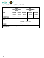
4.2 Rückkanalmodul / Return path module
Rückkanalmodule
passiv
Return path modules
passive
Rückkanalmodule
aktiv
Return path modules
active
Type
RPM 0/30
RPM 0/65
RPM 20/65
RPM 30/30
RPM 30/65
Artikel-Nr.
Article no.
1487900
1488000
1488400
1488310
1488410
Frequenzbereich
Frequency range
4-30 MHz
4-65 MHz
4-65 MHz
4-30 MHz
4-65 MHz
Verstärkung
Gain
-1 dB
20 dB
30 dB
Pegelsteller
Attenuator
1 Steckplatz / 1 Plug-in place
Entzerrer
Equalizer
1 Steckplatz / 1 Plug-in place
Max. Ausgangspegel
Max. output level
-
117 dBµV

13
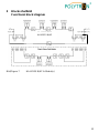
5 Blockschaltbild
Functional block diagram
Bild/Figure 7 HA 40125 N/AP & Modul(e)
HA 40119 F/AP
HA 40125 F/AP
HA 45125 F/AP
HA 40125 N/AP

14
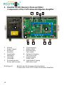
6 Bauteile der BK-Hausanschlussverstärker
Components of the CATV-Home-Distribution-Amplifier
1 Netzteil 6 Signalausgang
Power Supply Signal output
2 Entzerrer 7 Messausgang
Equalizer Test output
3 Pegelsteller 8 Testpunkt Eingang
Attenuator Test point input
4 Interstage 9 Signaleingang
Interstage Signal input
5 Rückkanalmodul 10 Pegelsteller Eingang
Return path module Attenuator input
Bild/Figure 8 Bauteile der BK-Hausanschlussverstärker
Components of the CATV-Home-Distribution-Amplifiers
1
2
3
5
6
7
8
9
10
4
2

15
Notizen/ Notes

16
Polytron-Vertrieb GmbH
Postfach 10 02 33
75313 Bad Wildbad
Zentrale/Bestellannahme
H.Q. Order department + 49 (0) 70 81/1702 - 0
Technische Hotline
Technical hotline + 49 (0) 70 81/1702 - 0
Telefax + 49 (0) 70 81/ 1702 - 50
Internet http://www.polytron.de
Email [email protected]
Technische Änderungen vorbehalten
Subject to change without prior notice
Copyright © Polytron-Vertrieb GmbH
-
 1
1
-
 2
2
-
 3
3
-
 4
4
-
 5
5
-
 6
6
-
 7
7
-
 8
8
-
 9
9
-
 10
10
-
 11
11
-
 12
12
-
 13
13
-
 14
14
-
 15
15
-
 16
16


POLYTRON HA 36121 Home distribution amplifier 36 dB Bedienungsanleitung
- Typ
- Bedienungsanleitung
in anderen Sprachen
Verwandte Artikel
-
POLYTRON HG 40125 CATV amplifier 1GHz 40 dB Bedienungsanleitung
-
-
-
-
-
-
-
-
-