Pride FULL-SIZE 613 Bedienungsanleitung
- Kategorie
- Roller
- Typ
- Bedienungsanleitung
Dieses Handbuch eignet sich auch für

Serial #/série #/serie #/seriell #/serie # /seriale #
Provider:
Détaillant:
Leverancier:
Name:
Rivenditore:
Proveedor:________________________________________________________________________
Address:
Adresse:
Adres:
Adresse:
Indirizzo:
Dirección:________________________________________________________________________
Telephone:
Téléphone:
Telefoon nummer:
Tel. Nummer:
Telefono:
Número de teléfono:________________________________________________________________
Purchase Date:
Date d’achat:
Koop Datum:
Kaufdatum:
Data di acquisto:
Fecha de compra:___________________________________________________________________
Please fi ll out the following information for quick reference:
S.V.P. veuillez compléter les informations ci dessous:
Vul alstublieft de volgende informatie in voor snelle referentie:
Mein autorisierter Fachhändler ist:
Informazioni di riferimento:
Por favor, rellene la siguiente información para tener siempre a mano:

4
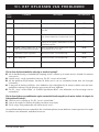
SCOOTER FEATURES TABLE
Copyright © 2017
INFMANU4530/Rev D/September 2017
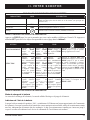
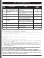
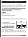
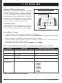
NOTE: Please become familiar with your scooter’s model number. The number can be found on the product
specifi cation sheet in your owner’s package. Throughout this owner’s manual, Scooter attributes are identifi ed by
model number (far left-hand column on Scooter Features Table). Knowing your unit’s model number will aid you
in determining your particular scooter’s unique characteristics.
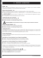
I
NTENDED USE
The intended use of the mobility device is to provide mobility to persons limited to a seated position that have the
capability of operating a scooter.
REGARDING DEVICES FOR PRESCRIPTION USE
CAUTION! Federal law restricts this device to sale by or on the order of a physician or
other certifi ed personnel licensed by the law of the State (US only) or region in which
this personnel practices to use or order the use of this device.
NOTE: This owner’s manual is compiled from the latest specifi cations and product information available at
the time of publication. We reserve the right to make changes as they become necessary. Any changes to our
products may cause slight variations between the illustrations and explanations in this manual and the product
you have purchased. The latest/current version of this manual is available on our website.
NOTE: This product is compliant with WEEE, RoHS, and REACH directives and requirements.
NOTE: This product complies with IPX4 Classifi cation (IEC 60529).
NOTE: The scooter and its components are not made with natural rubber latex. Consult with the manufacturer
regarding any after-market accessories.
*NOTE: Scooter options vary by country. Please contact your Provider to determine which options are available for
your Scooter.

Full-size Scooter Series 3
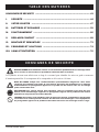
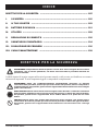
CONTENTS
SAFETY GUIDELINES ............................................................................................... 3
I. SAFETY ............................................................................................................ 4
II. YOUR SCOOTER .............................................................................................. 7
III. BATTERIES AND CHARGING ......................................................................... 19
IV. OPERATION ................................................................................................... 26
V. COMFORT ADJUSTMENTS ............................................................................ 28
VI. DISASSEMBLY AND ASSEMBLY .................................................................... 32
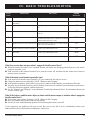
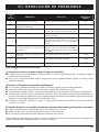
VII. BASIC TROUBLESHOOTING .......................................................................... 34
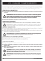
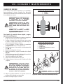
VIII. CARE AND MAINTENANCE ........................................................................... 36
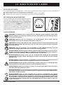
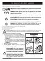
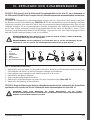
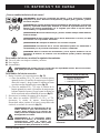
SAFETY GUIDELINES
WARNING! An authorized Provider or qualifi ed technician must perform the initial setup of this
scooter and must perform all of the procedures in this manual.
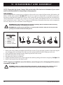
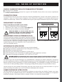
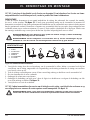
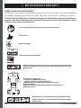
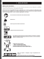
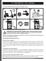
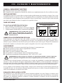
The symbols below are used throughout this owner’s manual and on the scooter to identify warnings and important
information. It is very important for you to read them and understand them completely.
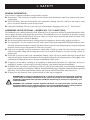
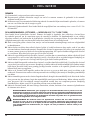
WARNING! Indicates a potentially hazardous condition/situation. Failure to follow designated
procedures can cause either personal injury, component damage, or malfunction. On the
product, this icon is represented as a black symbol on a yellow triangle with a black border.
MANDATORY! These actions should be performed as specifi ed. Failure to perform mandatory
actions can cause personal injury and/or equipment damage. On the product, this icon is
represented as a white symbol on a blue dot with a white border.
PROHIBITED! These actions are prohibited. These actions should not be performed at any
time or in any circumstances. Performing a prohibited action can cause personal injury and/or
equipment damage. On the product, this icon is represented as a black symbol with a red circle
and red slash.

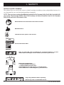
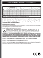
4 Full-size Scooter Series
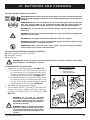
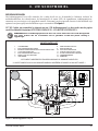
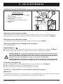
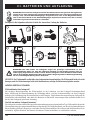
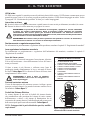
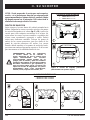
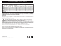
Manufactured in
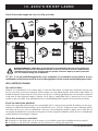
Fully charge batteries before operating.
Remove key from an unattended Scooter.
Battery Set Confi guration:
+ = Positive (Red) Terminal Post
- = Negative (Black) Terminal Post
Connect Red wires to Red Positive (+) Terminal Posts.
Connect Black wire to Black Negative (-) Terminal Posts.
Read and follow the information in the owner’s manual.
I. SAFETY
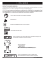
PRODUCT SAFETY SYMBOLS
The symbols below are used on the scooter to identify warnings, mandatory actions, and prohibited actions. It is
very important for you to read and understand them completely.
NOTE: There are more warnings identifi ed and explained in the Consumer Safety Guide that is included with
your scooter. Please become familiar with all the warnings and safety information found in the Consumer
Safety Guide and refer to this resource often.
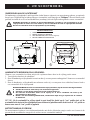
Indicates tie-down points on the Scooter.
Scooter information label
Does not meet ISO 7176-19 standards for occupied transport in a motor
vehicle. When travelling in a motor vehicle, do not sit in your scooter.
MODEL #
60 AMP
CIRCUIT BREAKER
125A/50V
BATTERY
BATTERY
OR

Full-size Scooter Series 5
I. SAFETY
GENERAL
MANDATORY! Do not operate your new scooter for the fi rst time without completely reading and
understanding this owner’s manual and the Consumer Safety Guide.
Your scooter is a state-of-the-art life-enhancement device designed to increase mobility. We provide an extensive
variety of products to best fi t the individual needs of the scooter user. Please be aware that the fi nal selection and
purchasing decision regarding the type of scooter to be used is the responsibility of the scooter user, who is capable
of making such a decision and his/her healthcare professional (i.e., medical doctor, physical therapist, etc.).
The contents of this manual are based on the expectation that a mobility device expert has properly fi tted the
scooter to the user and has assisted the prescribing healthcare professional and/or the authorized Provider in the
instruction process for the use of the product.
There are certain situations, including some medical conditions, where the scooter user will need to practice
operating the scooter in the presence of a trained attendant. A trained attendant can be defi ned as a family member
or care professional specially trained in assisting a scooter user in various daily living activities.
As you begin using your scooter during daily activities, you will probably encounter situations in which you will
need some practice. Simply take your time and you will soon be in full and confi dent control as you maneuver
through doorways, on and off elevators, up and down ramps, and over moderate terrain.
Additional general information can be found on the supplemental information sheets and booklets included in
your Owner’s Package. Please fully read and review the information, and keep it readily available for future
reference.
Below are some precautions, tips, and other safety considerations that will help you become accustomed to
operating the scooter safely.
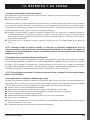
PRE-RIDE SAFETY CHECK
Get to know the feel of your scooter and its capabilities. We recommend that you perform a safety check before
each use to make sure your scooter operates smoothly and safely.
Perform the following inspections prior to using your scooter:
Check the condition of the tires. Make sure they are not damaged or excessively worn.
Check all electrical connections. Make sure they are tight and not corroded.
Check all harness connections. Make sure they are secured properly.
Check the brakes to ensure they operate properly.
Check the battery condition meter to ensure the batteries are fully charged.
Ensure the manual freewheel lever is in drive mode before sitting on the scooter.
If you discover a problem, contact your authorized Provider for assistance. Please refer to the Contact Information
insert in your Owner’s Package.

6 Full-size Scooter Series
I. SAFETY
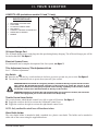
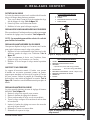
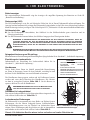
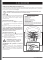
BRAKING INFORMATION
Your scooter is equipped with these powerful brake systems:
Regenerative: Uses electricity to rapidly slow the vehicle when the throttle control lever returns to the center/
stop position.
Disc Park Brake: Activates mechanically after regenerative braking slows the vehicle to near stop or when
power is removed from the system for any reason.
(Optional) Handbrake: This lever provides you with emergency stopping power. See II. “Your Scooter.”
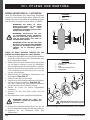
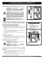
HANDBRAKE LEVER (OPTIONAL — MODELS 613, 713, 714 AND 713ES)
The handbrake lever contains hydraulic fl uid. When the lever is depressed, the fl uid is pushed through the brake
line to engage the brake pads against the brake discs. The handbrake lever is a completely sealed unit, meaning
that the hydraulic fl uid should not leak; however, there are certain safety measures that should be taken if the
handbrake lever becomes cracked or damaged.
Do not touch spilled material unless wearing protective equipment, such as safety goggles and gloves.
For small spills, cover the material with dry earth, sand or other non-combustible absorbent material. Once
absorbed, enclose the material in a plastic bag and contact your local waste disposal agency for proper disposal
measures. Do not expose the material to waterways or sewers.
If the eyes are exposed, check for and remove contact lenses. Flush eyes with cool, clean, low-pressure water
while occasionally lifting and lowering the eyelids. Seek medical attention if excessive tearing, redness or
pain persists.
If the skin is exposed, remove all contaminated clothing. Wipe off excess material and wash exposed skin
with soap and water. Seek medical attention if skin appears damaged or if irritation persists. Thoroughly clean
contaminated clothing before reuse. Discard contaminated leather goods.
If ingested, do not induce vomiting or give anything to drink unless directed to by a physician. Never give
anything by mouth to a person who is not fully conscious. Seek medical attention immediately.
If inhaled, move the affected individual to fresh air. If the affected individual is not breathing, immediately
begin rescue breathing. If breathing is diffi cult, 100% humidifi ed oxygen should be administered by a qualifi ed
individual. Seek medical attention immediately and keep the affected individual warm and at rest.
If ignited, use dry chemical, foam, carbon dioxide or water fog to extinguish.
WARNING! Do not modify the handbrake lever or attempt to replace the hydraulic fl uid. If damage
occurs, follow the safety information in this section and contact your authorized dealer for
handbrake replacement. The hydraulic handbrake should only be serviced or replaced by your
authorized dealer.
WARNING! The handbrake contains hydraulic fl uid that can cause mild skin, eye and nasal/
bronchial irritation. Do not attempt to adjust or service the handbrake without proper protective
equipment such as safety goggles and gloves and wash hands after handling.

Full-size Scooter Series 7
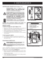
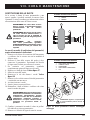
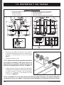
II. YOUR SCOOTER
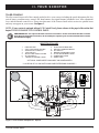
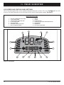
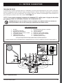
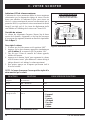
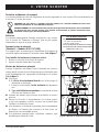
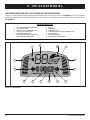
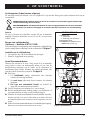
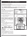
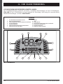
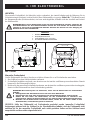
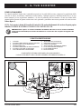
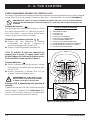
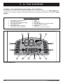
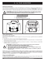
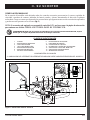
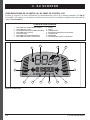
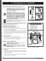
TILLER CONSOLE
The tiller console houses all of the controls needed to drive your scooter, including the speed adjustment dial, key
switch, battery condition meter, status LED, horn buttons, turn signal buttons, handbrake lever, tiller adjustment
lever, and the throttle control lever. Please note that some of the features listed in this section are optional items
and may not appear on your scooter. See fi gure 1.
NOTE: If your scooter is equipped with an LCD Control Panel, please advance to the page in this section that
begins TILLER CONSOLE: LCD CONTROL PANEL.
PROHIBITED! Do not expose the tiller console to moisture. In the event that the tiller console
does become exposed to moisture, do not attempt to operate your scooter until the tiller console
has dried thoroughly.
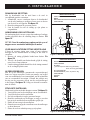
IDENTIFICATION KEY
1. HORN BUTTON
2. *LEFT TURN SIGNAL BUTTON
3. *HAZARD LIGHTS SWITCH
4. LIGHT SWITCH
5. *RIGHT TURN SIGNAL BUTTON
6. *HI-LOW SWITCH
7. THROTTLE CONTROL LEVER
8. SPEED ADJUSTMENT DIAL
9. BATTERY CONDITION METER
10. KEY SWITCH
11. MIRROR AND MIRROR PLUGS
12. *TILLER ADJUSTMENT LEVER
13. *HANDBRAKE LEVER
14. *BRAKE LOCK
11
8 9 10
13
12
11
7
1
2 5
11
6
4
3
14
7
Figure 1. Tiller Console Components - Style A
*OPTIONAL COMPONENTS AVAILABLE ON SOME MODELS
**LOCATION OF HI-LOW SWITCH MAY VARY DEPENDING ON MODEL**

8 Full-size Scooter Series
II. YOUR SCOOTER
Horn Buttons
These buttons activate a warning horn. Your scooter must be powered up for the horn to be operational. Do not
hesitate to use the warning horn when doing so may prevent accident or injury.
Turn Signal Buttons
Use these buttons to turn on the left and right turn signal (amber) lights.
Push the left button to activate the left turn signal light. The turn signal LED located in the battery condition
meter will fl ash.
Push the right button to activate the right turn signal light. The turn signal LED located in the battery condition
meter will fl ash.
The turn signals are timed to shut off automatically.
Lights Switch
This switch controls your scooter’s lighting system.
Toggle the switch forward to turn on the lighting system.
Toggle the switch rearward to turn off the lighting system.
WARNING! Scooter users are required to use their lights when visibility is restricted—day or
night.
Hazard Lights Switch
This switch activates the 4-way fl ashers on your scooter.
Toggle the hazard lights switch forward to turn on the fl ashers.
Toggle the hazard lights switch rearward to turn off the fl ashers.
Hi-Low Switch
This switch toggles the scooter’s speed between Hi and Low. Toggle the switch forward (Hi) to achieve the
maximum preprogrammed speed for the scooter. Toggle the switch rearward (Low) to achieve half the maximum
preprogrammed speed of the scooter.
Throttle Control Lever
This lever allows you to control the forward speed and the reverse speed of your scooter up to the maximum speed
you preset with the speed adjustment dial.
To Move Forward, use either of the following:
Use your left thumb to push the left side of the throttle control lever.
Use your right hand fi ngers to pull back on the right side of the throttle control lever.
To Move Rearward, use either of the following:
Use your right thumb to push the right side of the throttle control lever.
Use your left hand fi ngers to pull back on the left side of the throttle control lever.
Release the throttle control lever and allow your scooter to come to a complete stop before engaging the other side
of the lever. When the throttle control lever is completely released, it automatically returns to the center “stop”
position and engages your scooter’s brakes.
Speed Adjustment Dial
This dial allows you to preselect and limit your scooter’s top speed.
The image of the tortoise represents the slowest speed setting
The image of the hare represents the fastest speed setting.

Full-size Scooter Series 9
II. YOUR SCOOTER
Battery Condition Meter
When the key is fully inserted and turned clockwise to power up your scooter, this meter indicates the approximate
battery voltage strength. For further information on battery charging, see III. “Batteries and Charging.”
Status LED
The status LED alerts you to electrical problems that may occur with the scooter. The LED remains constantly lit
while your scooter is on. If your scooter develops an electrical problem, the status LED will fl ash a code. See VII.
“Basic Troubleshooting” for fl ash codes.
Key Switch
Insert the key into the key switch and turn it clockwise to power up (turn on) your scooter.
Turn the key counterclockwise to power down (turn off) your scooter.
WARNING! When faced with an emergency situation, switch off the key to power off the scooter.
Use caution. Be advised that turning off power to the scooter may cause the scooter to stop
abruptly. To release the emergency stop and restore driving capability to the scooter, release
the throttle control lever and then switch on the key to the scooter.
WARNING! If the key is turned to the “off” position while your scooter is in motion, the electronic
brakes will engage and your scooter will come to an abrupt stop.
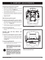
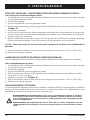
Mirror Positioning and Adjustment
For information on positioning and adjusting your mirror, see V. “Comfort Adjustments.”
Tiller Angle Adjustment
For information on positioning and adjusting your tiller, see V. “Comfort Adjustments.”
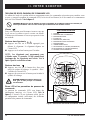
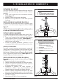
Handbrake Lever
This lever provides you with emergency stopping power. When
in motion, release the throttle control lever and gently squeeze the
handbrake lever to come to a stop.
The handbrake can be locked and used as a parking brake by squeezing the
handbrake lever fully and moving the brake lock to the locked position.
See fi gure 1. To release the brake lock, fully squeeze the handbrake.
WARNING! The handbrake is intended for use as an
emergency brake and/or parking brake only.
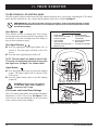
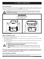
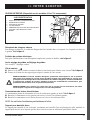
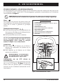
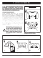
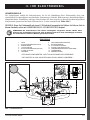
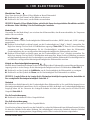
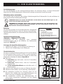
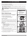
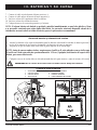
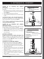
Off-board Charger Port
The off-board charger power cord plugs into this port during battery
charging. The off-board charger port is located on the tiller. See fi gure 2.
Electrical System Fuses
Your scooter is equipped with a series of electrical system fuses, which
help protect the off-board charging system, key switch and lighting system
from receiving an overload of electrical current. These fuses are the same
type used in automobiles and are located in a compartment on the tiller.
See fi gure 2. See VIII. “Care and Maintenance” for fuse replacement.
NOTE: Keep all electrical areas clean and free of moisture and
foreign material.
IDENTIFICATION KEY
1. OFF-BOARD CHARGER PORT
2. OFF-BOARD CHARGER FUSE
3. KEY SWITCH FUSE
4. LOWER HEADLIGHT FUSE
5. REAR TAIL LIGHTS FUSE
6. LEFT TURN SIGNAL FUSE
7. RIGHT TURN SIGNAL FUSE
1
2
4
6
7
5
3
Figure 2. Off-board Charger Port/Tiller
Console Fuses

10 Full-size Scooter Series
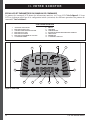
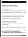
TILLER CONSOLE: LCD CONTROL PANEL
The tiller console and lower tiller house all of the controls needed to drive your scooter, including the LCD control
panel, throttle control levers, key switch, and the throttle control lever switch. See fi gure 3.
PROHIBITED! Do not expose the tiller console to moisture. In the event that the tiller console
does become exposed to moisture, do not attempt to operate your scooter until the tiller console
has dried thoroughly.
Horn Buttons
These buttons activate a warning horn. Your scooter
must be powered up for the horn to be operational. Do
not hesitate to use the warning horn when doing so
may prevent accident or injury.
Turn Signal Buttons
Press the appropriate turn signal button once to
activate it. The turn signal will fl ash on the LCD
screen.
Press the same signal button to turn it off.
NOTE: The turn signals are timed to shut off after
15 seconds. A warning beep will sound as long as the
turn signal is on. See fi gure 5 for volume control.
Lights Button
Press the lights button once to activate the lighting
system. The light symbol will be shown on the
LCD screen.
Press the lights button again to turn the lighting
system off.
WARNING! Scooter users are required
to use their lights when visibility is
restricted—day or night.
LCD Screen and Control Panel Settings
The LCD control panel offers easily intuited feedback
information via the LCD screen. See fi gure 3. The
LCD screen is also used during the set-up (activation)
of the various control panel settings.
II. YOUR SCOOTER
IDENTIFICATION KEY
1. HORN BUTTON
2. TURN SIGNAL BUTTONS
3. LIGHTS BUTTON
4. LCD SCREEN
5. SET BUTTON
6. HAZARD LIGHTS BUTTON
7. MODE BUTTON
8. HI-LOW BUTTON
9. SPEED ADJUSTMENT
(INCREASE)
10. SPEED ADJUSTMENT
(DECREASE)
11. THROTTLE CONTROL
10
9
8
2
3
1
1
2
7
6
5
4
11
Figure 3. LCD Control Panel - Style B

Full-size Scooter Series 11
Hazard Lights Button
This button activates the 4-way yellow fl ashers on your scooter.
Press the button once to turn on the fl ashers.
Press the button again to turn off the fl ashers.
NOTE: The 4-way fl ashers will fl ash and a warning beep will sound as long as the hazard lights are on. See
fi gure 5 for volume control.
Mode Button
Use the mode button to scroll between the odometer, tripometer, temperature, and clock.
High-Low Button
This button toggles the scooter’s speed between HIGH and LOW.
Press the High-Low button once to set the speed adjustment to High. The High-Low indicator will display on
the LCD screen. See fi gure 4. Using this setting in conjunction with the speed adjustment buttons will allow
the scooter to achieve speeds up to the maximum preprogrammed speed for the scooter.
Press the High-Low button again to set the speed adjustment to Low. The High-Low indicator will not display
on the LCD screen. Using this setting in conjunction with the speed adjustment buttons will allow the scooter
to achieve speeds up to the half the maximum preprogrammed speed for the scooter.
Speed Adjustment Buttons
These adjustment buttons enable you to pre-select and limit your scooter’s speed. This is indicated by the maximum
speed indicator on the LCD screen. See fi gure 4.
Press the image of the tortoise to decrease the speed of the scooter.
Press the image of the hare to increase the speed of the scooter.
NOTE: The more bars shown on the maximum speed indicator, the faster your pre-selected maximum speed
will be. See fi gure 4.
Throttle Control Levers
These levers allow you to control the forward speed and the reverse speed of your scooter up to the maximum
speed you preset with the speed adjustment buttons. A throttle control lever is located on the underside of the left
and right side of the tiller handle. See Figure 3.
To Move Forward:
Squeeze the rear part of the throttle control lever.
To Move Rearward:
Squeeze the front part of the throttle control lever.
Release the throttle control lever and allow your scooter to come to a complete stop before engaging the other side
of the lever. When the throttle control lever is completely released, it automatically returns to the center “stop”
position and engages your scooter’s brakes.
II. YOUR SCOOTER

12 Full-size Scooter Series
II. YOUR SCOOTER
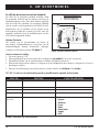
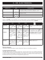
LCD SCREEN AND CONTROL PANEL SETTINGS
The LCD control panel offers easily intuited feedback information via the LCD screen. See fi gure 4. The LCD
screen is also used during the set-up (activation) of the various control panel settings. See chart 1.
IDENTIFICATION KEY
1. BATTERY CONDITION INDICATOR
2. LIGHTS INDICATOR
3. SPEED/ERROR CODE/VOLUME
4. HI-LOW INDICATOR
5. UNIT INDICATOR
6. MAXIMUM SPEED INDICATOR
7. RIGHT TURN INDICATOR
8. AM/PM
9. CLOCK
10. TEMPERATURE
11. DISTANCE/TIME/TEMP/ERROR MESSAGE
12. TRIPOMETER
13. ODOMETER
14. LEFT TURN INDICATOR
13
14
7
1012 11 9 8
6
54
3
2
1
Figure 4. LCD Screen

Full-size Scooter Series 13
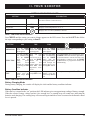
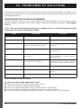
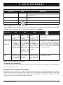
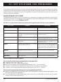
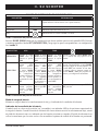
SETTING INFORMATION CHART
SETTING CODE INFORMATION
Odometer
ODO
Measures mph, km/h, and hours of use. Also displays total distance traveled
over life of scooter. (Cannot be reset.)
Tripometer
TRIP
Displays trip distance traveled. Can be reset to “0”.
Temperature
TEMP
Displays current temperature in °F or °C.
Clock Displays time in 12-hour (AM/PM) or 24-hour.
SETTING ODO TRIP TEMP
OPERATION
Press the MODE
button until ODO
option appears.
Press the MODE
button until TRIP
option appears.
Press the MODE
button until TEMP
option appears.
Press and hold MODE button until the clock
symbol appears on screen.
SELECTION
Press and hold SET,
then simultaneously
press the MODE
button until the
setting option
flashes. Scroll
through the options
by pressing the SET
button.
Press and hold
SET, then
simultaneously
press the MODE
button for 2
seconds and
release. Press and
hold SET until
Tripometer resets
to 0.0.
Press and hold SET,
then simultaneously
press the MODE
button until the
setting option fl ashes.
Scroll through the
options (°F or °C) by
pressing SET button.
Press and hold SET, then simultaneously press
the MODE button until the hour digit fl ashes.
Use the SET button to increase the hour to the
correct number. Continue to use the MODE
and SET buttons to program the minutes and
AM/PM setting.
EXIT
When desired option
flashes, press any
button except SET
to exit.
Press any button
except SET to exit.
When your choice is
fl ashing, press any
button except SET to
exit.
Press any button except MODE or SET to exit.
II. YOUR SCOOTER
Chart 1. LCD Control Panel Information
Chart 2. LCD Control Panel Information
Press MODE until the setting you want to change appears on the LED screen. Press and hold SET then follow
the steps corresponding to your setting in chart 2.
Battery Charging Mode
During battery charging, the console will display the clock and the battery condition indicator.
Battery Condition Indicator
When the key is turned to the “on” position, this LED indicator gives an approximate reading of battery strength.
When the scooter’s battery voltage reaches a low enough level, a warning beep will sound once, indicating the
batteries need charging. The warning beep will not sound again until the scooter is restarted or the throttle control
lever is pressed.

14 Full-size Scooter Series
II. YOUR SCOOTER
Maximum Speed Indicator LED
The maximum speed indicator displays the maximum
speed selected with the speed adjustment buttons. The
more bars that are lit, the faster the speed. The maximum
scooter speed will be determined by the HIGH-LOW
setting, which limits the maximum speed to half when
set to LOW. The actual travel speed will be shown in
the speed display on the LCD screen.
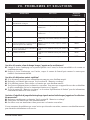
Volume Control
The volume of the hazard lights, horn, low voltage,
turn signals, and error message beeps can be increased,
decreased, or turned off separately. See fi gure 5.
To set the volume:
1. Ensure the key is in the “off” position.
2. Press the appropriate two buttons simultaneously
(see chart 3), and turn the key to the “on” position.
3. Once the volume control screen appears, release the
buttons.
4. Press the hare button to increase the volume and the
tortoise button to decrease the volume of the beep
(0 indicates off and 4 indicates the loudest volume).
5. To exit, press any button except the hare or tortoise.
NOTE: The error message language option is set the
same way as the volume.
IDENTIFICATION KEY
1. VOLUME/LANGUAGE OPTION
2. FUNCTION INDICATOR
1
2
Figure 5. Volume Control Display
Chart 3. Volume Control Information
FUNCTION BUTTONS FUNCTION INDICATOR
Hazard Lights SET + HAZARD LIGHTS SET 1
Horn SET + HORN SET 2
Low Voltage SET + LEFT TURN INDICATOR SET 3
Turn Signals SET + RIGHT TURN INDICATOR SET 4
Error Message
Language
Option
SET + LIGHTS
SET 5
6 - Spanish
5 - Italian
4 - French
3 - German
2 - Dutch
1 - English
0 - Close

Full-size Scooter Series 15
II. YOUR SCOOTER
Off-board Charger Port
The off-board charger power cord plugs into this port during battery charging. The off-board charger port will be
located on the tiller. See fi gure 6.
Electrical System Fuses
For information and a complete description of the fuse system, see fi gure 2.
Tiller Adjustment Lever or Tiller Adjustment Knob
See V. “Comfort Adjustments”.
Key Switch
Insert the key into the key switch and turn it clockwise to power up (turn on) your scooter. See fi gure 6.
Turn the key counterclockwise to power down (turn off) your scooter.
WARNING! When faced with an emergency situation, switch off the key to power off the scooter.
Use caution. Be advised that turning off power to the scooter may cause the scooter to stop
abruptly. To release the emergency stop and restore driving capability to the scooter, release
the throttle control lever and then switch on the key to the scooter.
WARNING! If the key is turned to the “off” position while your scooter is in motion, the electronic
brakes will engage and your scooter will come to an abrupt stop!
Throttle Control Lever Switch
This switch dictates which throttle control lever (left or right) will function. See fi gure 6.
Toggle the switch to the left to activate the left throttle control lever.
Toggle the switch to the right to activate the right throttle control lever.
NOTE: Only one throttle control lever will function at a time.
Water Bottle Holder
The water bottle holder is intended to hold a standard size, plastic water bottle. The holder can be attached to
either side of the scooter using the supplied hardware.
LOWER TILLER (available on models 614 and 714 only)
IDENTIFICATION KEY
1. OFF-BOARD CHARGER PORT
2. FUSE PANEL
3. TILLER ADJUSTMENT KNOB
4. KEY SWITCH
5. THROTTLE CONTROL LEVER SWITCH
6. WATER BOTTLE HOLDER
7. MIRROR
Figure 6. Lower Tiller Components
6
2
1
3 5 4
7

16 Full-size Scooter Series
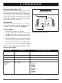
II. YOUR SCOOTER
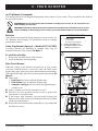
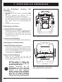
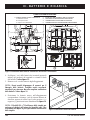
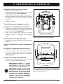
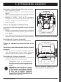
REAR COMPONENTS
The manual freewheel lever, anti-tip wheels (if equipped), motor/transaxle assembly, and optional safety fl ag
brackets are located on your scooter as shown. See fi gure 7. The main circuit breaker (reset button) and batteries
(not shown) are also located on the rear component section of your scooter.
WARNING! Before placing your scooter into or taking it out of freewheel mode, remove the key
from the key switch. Never sit on a scooter when it is in freewheel mode. Never put a scooter in
freewheel mode on any incline.
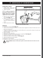
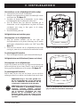
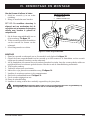
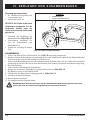
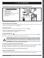
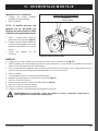
MANUAL FREEWHEEL LEVER
Whenever you need or want to push your scooter for short distances, you can put it in freewheel mode.
1. Remove the key from the key switch.
2. Push forward on the manual freewheel lever to disable the drive system and the brake system. This will enable
you to push the scooter.
3. Pull back on the manual freewheel lever to reengage the drive and the brake systems and take your scooter
out of freewheel mode.
WARNING! When your scooter is in freewheel mode, the braking system is disengaged.
Disengage the drive motors only on a level surface.
Ensure the key is removed from the key switch.
Stand to the side of the scooter to engage or disengage freewheel mode. Never sit on a
scooter to do this.
After you have fi nished pushing your scooter, always return it to the drive mode to lock the
brakes.
NOTE: If the scooter is placed in freewheel mode (manual freewheel lever forward) while the key is in the
“on” position, the scooter will not run until the manual freewheel lever is pushed backward and the key is
turned to the “off” position, then back to the “on” position.
MOTOR/TRANSAXLE ASSEMBLY
The motor/transaxle assembly is an electromechanical unit that converts electrical energy from your scooter’s
batteries into the controlled mechanical energy that drives the scooter’s wheels.
Figure 7. Rear Components
IDENTIFICATION KEY
1. MANUAL FREEWHEEL LEVER
2. MOTOR/TRANSAXLE ASSEMBLY
3. ANTI-TIP WHEELS (if equipped)
4. SAFETY FLAG BRACKETS
3
2
3
2
1
4
1
A B

Full-size Scooter Series 17
II. YOUR SCOOTER
Anti-Tip Wheels (If equipped)
The anti-tip wheels are an integral and important safety feature of your scooter. They are bolted to the frame at
the rear of the scooter.
PROHIBITED! Do not remove the anti-tip wheels or modify your scooter in any way that is not
authorized by your Provider.
WARNING! The anti-tip wheels may cause interference with the smooth transition of your scooter
when ascending or descending a curb. Contact your authorized Provider for more information.
Batteries
The batteries store electrical energy that powers your scooter. See
III. “Batteries and Charging” for information on how to charge
your scooter batteries.
Safety Flag Bracket (Optional — Models 613/713/713ES)
Accessory brackets for installing an optional safety fl ag are
mounted at the rear of the scooter. See fi gure 7.
To install the safety fl ag:
1. Remove the cap from the top of the bracket.
2. Insert the fl ag pole into the opening.
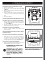
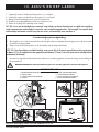
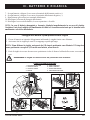
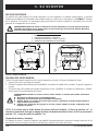
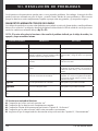
Main Circuit Breaker
When the voltage in the batteries becomes low or your scooter
is heavily strained because of excessive loads, the main circuit
breaker may trip to protect the motor and electronics from damage.
When the breaker trips, the entire electrical system shuts down. See
fi gure 8.
Three types:
1. Reset lever fl ips down when the breaker trips.
2. Reset button pops out when the breaker trips.
3. Automatic reset type will reset itself after approximately
a minute or so.
Allow a minute or so for the electronics to “rest.”
Push the reset lever up until you hear a click, or push in the
reset button to reset the breaker.
If the breaker trips frequently, you may need to charge the
batteries more often or have your authorized Provider perform
a load test on the batteries.
If the main circuit breaker trips repeatedly, see your authorized
Provider for service.
IDENTIFICATION KEY
1. LEVER STYLE
a. reset lever
b. manual shut-off button
2. RESET BUTTON STYLE
3. AUTOMATIC RESET STYLE
(MODELS 614 OR 714)
Figure 8. Main Circuit Breaker
1
a b
2
3

18 Full-size Scooter Series
II. YOUR SCOOTER
NOTE: If the scooter is placed in freewheel mode (manual
freewheel lever forward) while the key is in the “on”
position, the scooter will not run until the manual freewheel
lever is pushed backward and the key is turned to the “off”
position, then back to the “on” position.
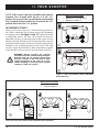
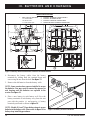
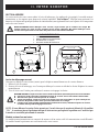
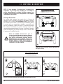
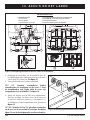
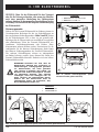
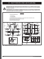
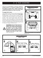
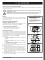
SECUREMENT POINTS
Always secure the scooter in a forward-facing position in
the vehicle. Attach the four tie-down straps to the designated
securement points. See fi gures 9 and 10. Tighten the straps
to suffi ciently remove all slack. Never attach tie-downs to
adjustable, moving, or removable parts of the scooter such as
armrests, shrouds, and wheels. These items should be removed.
Position the anchor points for the rear tie-down straps directly
behind the rear securement points on the scooter. The front
tie-down straps should anchor to fl oor points that are spaced
wider than the scooter to provide increased lateral stability.
WARNING! Ensure scooters are properly
secured to the motor vehicle during transport.
Scooters that are not properly secured can
become a hazard to the user and to other
vehicle passengers in the event of a crash,
sudden stopping, or swerving, as the scooter
could tip or slide out of place.
IDENTIFICATION KEY
1. MODELS 613, 713, AND 713ES
2. MODELS 614 AND 714
1. 3-WHEEL MODELS
2. 4-WHEEL MODELS
Figure 9. Rear Securement Points (Identifi ed
with black dots)
1
2
Figure 10. Front Securement Points (Identifi ed with black dots)
IDENTIFICATION KEY
2
1
2

Full-size Scooter Series 19
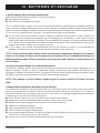
III. BATTERIES AND CHARGING
BATTERIES AND CHARGING
Your scooter requires two long-lasting, 12-volt, deep-cycle batteries that are sealed and maintenance free. They
are recharged by an off-board charging system.
Charge your scooter’s batteries for at least 8 to 14 hours prior to using it for the fi rst time.
Keep the batteries fully charged to keep your scooter running smoothly.
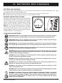
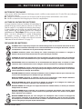
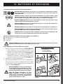
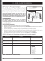
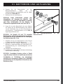
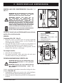
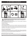
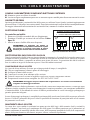
READING YOUR BATTERY VOLTAGE
The battery condition meter on the tiller console indicates
the approximate strength of your batteries using a color
code. From right to left, green indicates fully charged
batteries, yellow indicates a draining charge, and red
indicates that an immediate recharge is necessary. See
fi gure 11. To ensure the highest accuracy, the battery
condition meter should be checked while operating
your scooter at full speed on a dry, level surface. For
models with the LCD screen, please refer to the “Battery
Condition Indicator” section on page 13.
Figure 11. Battery Condition Meter
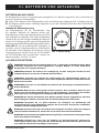
CHARGING YOUR BATTERIES
PROHIBITED! Removal of grounding prong can create electrical hazard. If necessary, properly
install an approved 3-pronged adapter to an electrical outlet having 2-pronged plug access.
PROHIBITED! Never use an extension cord to plug in your battery charger. Plug the charger
directly into a properly wired standard electrical outlet.
PROHIBITED! Do not allow unsupervised children to play near the scooter while the batteries
are charging. We recommend that you do not charge the batteries while the scooter is occupied.
MANDATORY! Read the battery charging instructions in this manual and in the manual supplied
with the battery charger before charging the batteries.
WARNING! Explosive gases may be generated while charging the batteries. Keep the scooter and
battery charger away from sources of ignition such as fl ames or sparks and provide adequate
ventilation when charging the batteries.
WARNING! You must recharge your scooter’s batteries with the supplied off-board charger. Do
not use an automotive-type battery charger.
WARNING! Inspect the battery charger, wiring, and connectors for damage before each use.
Contact your authorized Provider if damage is found.
WARNING! Do not attempt to open the battery charger case. If the battery charger does not
appear to be working correctly, contact your authorized Provider.
WARNING! If the battery charger is equipped with cooling slots, then do not attempt to insert
objects through these slots.
WARNING! Be aware that the battery charger case may become hot during charging. Avoid skin
contact and do no place on surfaces that may be affected by heat.
WARNING! If your battery charger has not been tested and approved for outdoor use, then do
not expose it to adverse or extreme weather conditions. If the battery charger is exposed to
adverse or extreme weather conditions, then it must be allowed to adjust to the difference in
environmental conditions before use indoors. Refer to the manual supplied with the battery
charger for more information.
1b1a

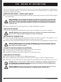
20 Full-size Scooter Series
III. BATTERIES AND CHARGING
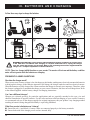
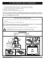
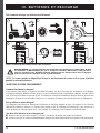
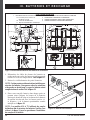
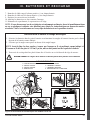
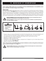
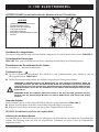
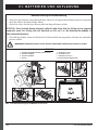
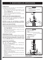
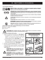
Follow these easy steps to charge the batteries:
1 2
4 5 6
8-14H
3
Figure 12. Battery Charging Procedures Diagram
WARNING! The LED lights on the charger indicate different charger conditions at various times.
If the LED does not indicate that charging is complete within 24 hours, unplug the charger
from the outlet and contact your Provider. Refer to the operating instructions supplied with the
charger for a complete explanation of these indicators.
NOTE: There is a charger inhibit function on your scooter. The scooter will not run and the battery condition
meter will not operate while the batteries are charging.
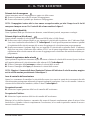
FREQUENTLY ASKED QUESTIONS
How does the charger work?
When your scooter’s battery voltage is low, the charger works harder, sending more electrical current to the batteries
to bring up their charge. As the batteries approach a full charge, the charger sends less and less electrical current.
When the batteries are fully charged, the current sent from the charger is at nearly zero amperage. Therefore, when
the charger is plugged in, it maintains the charge on your scooter’s batteries, but does not overcharge them. Refer
to the manual supplied with the battery charger for charging instructions.
Can I use a different charger?
Chargers are selected precisely for particular applications and are especially matched to the type, size and
chemical formulation of specifi c batteries. For the safest and most effi cient charging of your scooter’s batteries
we recommend only use of the charger supplied as original equipment with your product. Any charging method
resulting in batteries being charged individually is especially prohibited.
What if my scooter’s batteries won’t charge?
Ensure the red (+) and black (-) battery cables are connected properly to the battery terminals.
Ensure both ends of the charger power cord are inserted fully.
Seite wird geladen ...
Seite wird geladen ...
Seite wird geladen ...
Seite wird geladen ...
Seite wird geladen ...
Seite wird geladen ...
Seite wird geladen ...
Seite wird geladen ...
Seite wird geladen ...
Seite wird geladen ...
Seite wird geladen ...
Seite wird geladen ...
Seite wird geladen ...
Seite wird geladen ...
Seite wird geladen ...
Seite wird geladen ...
Seite wird geladen ...
Seite wird geladen ...
Seite wird geladen ...
Seite wird geladen ...
Seite wird geladen ...
Seite wird geladen ...
Seite wird geladen ...
Seite wird geladen ...
Seite wird geladen ...
Seite wird geladen ...
Seite wird geladen ...
Seite wird geladen ...
Seite wird geladen ...
Seite wird geladen ...
Seite wird geladen ...
Seite wird geladen ...
Seite wird geladen ...
Seite wird geladen ...
Seite wird geladen ...
Seite wird geladen ...
Seite wird geladen ...
Seite wird geladen ...
Seite wird geladen ...
Seite wird geladen ...
Seite wird geladen ...
Seite wird geladen ...
Seite wird geladen ...
Seite wird geladen ...
Seite wird geladen ...
Seite wird geladen ...
Seite wird geladen ...
Seite wird geladen ...
Seite wird geladen ...
Seite wird geladen ...
Seite wird geladen ...
Seite wird geladen ...
Seite wird geladen ...
Seite wird geladen ...
Seite wird geladen ...
Seite wird geladen ...
Seite wird geladen ...
Seite wird geladen ...
Seite wird geladen ...
Seite wird geladen ...
Seite wird geladen ...
Seite wird geladen ...
Seite wird geladen ...
Seite wird geladen ...
Seite wird geladen ...
Seite wird geladen ...
Seite wird geladen ...
Seite wird geladen ...
Seite wird geladen ...
Seite wird geladen ...
Seite wird geladen ...
Seite wird geladen ...
Seite wird geladen ...
Seite wird geladen ...
Seite wird geladen ...
Seite wird geladen ...
Seite wird geladen ...
Seite wird geladen ...
Seite wird geladen ...
Seite wird geladen ...
Seite wird geladen ...
Seite wird geladen ...
Seite wird geladen ...
Seite wird geladen ...
Seite wird geladen ...
Seite wird geladen ...
Seite wird geladen ...
Seite wird geladen ...
Seite wird geladen ...
Seite wird geladen ...
Seite wird geladen ...
Seite wird geladen ...
Seite wird geladen ...
Seite wird geladen ...
Seite wird geladen ...
Seite wird geladen ...
Seite wird geladen ...
Seite wird geladen ...
Seite wird geladen ...
Seite wird geladen ...
Seite wird geladen ...
Seite wird geladen ...
Seite wird geladen ...
Seite wird geladen ...
Seite wird geladen ...
Seite wird geladen ...
Seite wird geladen ...
Seite wird geladen ...
Seite wird geladen ...
Seite wird geladen ...
Seite wird geladen ...
Seite wird geladen ...
Seite wird geladen ...
Seite wird geladen ...
Seite wird geladen ...
Seite wird geladen ...
Seite wird geladen ...
Seite wird geladen ...
Seite wird geladen ...
Seite wird geladen ...
Seite wird geladen ...
Seite wird geladen ...
Seite wird geladen ...
Seite wird geladen ...
Seite wird geladen ...
Seite wird geladen ...
Seite wird geladen ...
Seite wird geladen ...
Seite wird geladen ...
Seite wird geladen ...
Seite wird geladen ...
Seite wird geladen ...
Seite wird geladen ...
Seite wird geladen ...
Seite wird geladen ...
Seite wird geladen ...
Seite wird geladen ...
Seite wird geladen ...
Seite wird geladen ...
Seite wird geladen ...
Seite wird geladen ...
Seite wird geladen ...
Seite wird geladen ...
Seite wird geladen ...
Seite wird geladen ...
Seite wird geladen ...
Seite wird geladen ...
Seite wird geladen ...
Seite wird geladen ...
Seite wird geladen ...
Seite wird geladen ...
Seite wird geladen ...
Seite wird geladen ...
Seite wird geladen ...
Seite wird geladen ...
Seite wird geladen ...
Seite wird geladen ...
Seite wird geladen ...
Seite wird geladen ...
Seite wird geladen ...
Seite wird geladen ...
Seite wird geladen ...
Seite wird geladen ...
Seite wird geladen ...
Seite wird geladen ...
Seite wird geladen ...
Seite wird geladen ...
Seite wird geladen ...
Seite wird geladen ...
Seite wird geladen ...
Seite wird geladen ...
Seite wird geladen ...
Seite wird geladen ...
Seite wird geladen ...
Seite wird geladen ...
Seite wird geladen ...
Seite wird geladen ...
Seite wird geladen ...
Seite wird geladen ...
Seite wird geladen ...
Seite wird geladen ...
Seite wird geladen ...
Seite wird geladen ...
Seite wird geladen ...
Seite wird geladen ...
Seite wird geladen ...
Seite wird geladen ...
Seite wird geladen ...
Seite wird geladen ...
Seite wird geladen ...
Seite wird geladen ...
Seite wird geladen ...
Seite wird geladen ...
Seite wird geladen ...
Seite wird geladen ...
Seite wird geladen ...
Seite wird geladen ...
Seite wird geladen ...
Seite wird geladen ...
Seite wird geladen ...
Seite wird geladen ...
Seite wird geladen ...
Seite wird geladen ...
Seite wird geladen ...
Seite wird geladen ...
Seite wird geladen ...
Seite wird geladen ...
Seite wird geladen ...
Seite wird geladen ...
Seite wird geladen ...
Seite wird geladen ...
Seite wird geladen ...
Seite wird geladen ...
Seite wird geladen ...
Seite wird geladen ...
Seite wird geladen ...
Seite wird geladen ...
Seite wird geladen ...
Seite wird geladen ...
Seite wird geladen ...
Seite wird geladen ...
Seite wird geladen ...
Seite wird geladen ...
Seite wird geladen ...
-
 1
1
-
 2
2
-
 3
3
-
 4
4
-
 5
5
-
 6
6
-
 7
7
-
 8
8
-
 9
9
-
 10
10
-
 11
11
-
 12
12
-
 13
13
-
 14
14
-
 15
15
-
 16
16
-
 17
17
-
 18
18
-
 19
19
-
 20
20
-
 21
21
-
 22
22
-
 23
23
-
 24
24
-
 25
25
-
 26
26
-
 27
27
-
 28
28
-
 29
29
-
 30
30
-
 31
31
-
 32
32
-
 33
33
-
 34
34
-
 35
35
-
 36
36
-
 37
37
-
 38
38
-
 39
39
-
 40
40
-
 41
41
-
 42
42
-
 43
43
-
 44
44
-
 45
45
-
 46
46
-
 47
47
-
 48
48
-
 49
49
-
 50
50
-
 51
51
-
 52
52
-
 53
53
-
 54
54
-
 55
55
-
 56
56
-
 57
57
-
 58
58
-
 59
59
-
 60
60
-
 61
61
-
 62
62
-
 63
63
-
 64
64
-
 65
65
-
 66
66
-
 67
67
-
 68
68
-
 69
69
-
 70
70
-
 71
71
-
 72
72
-
 73
73
-
 74
74
-
 75
75
-
 76
76
-
 77
77
-
 78
78
-
 79
79
-
 80
80
-
 81
81
-
 82
82
-
 83
83
-
 84
84
-
 85
85
-
 86
86
-
 87
87
-
 88
88
-
 89
89
-
 90
90
-
 91
91
-
 92
92
-
 93
93
-
 94
94
-
 95
95
-
 96
96
-
 97
97
-
 98
98
-
 99
99
-
 100
100
-
 101
101
-
 102
102
-
 103
103
-
 104
104
-
 105
105
-
 106
106
-
 107
107
-
 108
108
-
 109
109
-
 110
110
-
 111
111
-
 112
112
-
 113
113
-
 114
114
-
 115
115
-
 116
116
-
 117
117
-
 118
118
-
 119
119
-
 120
120
-
 121
121
-
 122
122
-
 123
123
-
 124
124
-
 125
125
-
 126
126
-
 127
127
-
 128
128
-
 129
129
-
 130
130
-
 131
131
-
 132
132
-
 133
133
-
 134
134
-
 135
135
-
 136
136
-
 137
137
-
 138
138
-
 139
139
-
 140
140
-
 141
141
-
 142
142
-
 143
143
-
 144
144
-
 145
145
-
 146
146
-
 147
147
-
 148
148
-
 149
149
-
 150
150
-
 151
151
-
 152
152
-
 153
153
-
 154
154
-
 155
155
-
 156
156
-
 157
157
-
 158
158
-
 159
159
-
 160
160
-
 161
161
-
 162
162
-
 163
163
-
 164
164
-
 165
165
-
 166
166
-
 167
167
-
 168
168
-
 169
169
-
 170
170
-
 171
171
-
 172
172
-
 173
173
-
 174
174
-
 175
175
-
 176
176
-
 177
177
-
 178
178
-
 179
179
-
 180
180
-
 181
181
-
 182
182
-
 183
183
-
 184
184
-
 185
185
-
 186
186
-
 187
187
-
 188
188
-
 189
189
-
 190
190
-
 191
191
-
 192
192
-
 193
193
-
 194
194
-
 195
195
-
 196
196
-
 197
197
-
 198
198
-
 199
199
-
 200
200
-
 201
201
-
 202
202
-
 203
203
-
 204
204
-
 205
205
-
 206
206
-
 207
207
-
 208
208
-
 209
209
-
 210
210
-
 211
211
-
 212
212
-
 213
213
-
 214
214
-
 215
215
-
 216
216
-
 217
217
-
 218
218
-
 219
219
-
 220
220
-
 221
221
-
 222
222
-
 223
223
-
 224
224
-
 225
225
-
 226
226
-
 227
227
-
 228
228
-
 229
229
-
 230
230
-
 231
231
-
 232
232
-
 233
233
-
 234
234
-
 235
235
-
 236
236
-
 237
237
-
 238
238
-
 239
239
-
 240
240
-
 241
241
-
 242
242
-
 243
243
-
 244
244


Pride FULL-SIZE 613 Bedienungsanleitung
- Kategorie
- Roller
- Typ
- Bedienungsanleitung
- Dieses Handbuch eignet sich auch für
in anderen Sprachen
- français: Pride FULL-SIZE 613 Le manuel du propriétaire
- español: Pride FULL-SIZE 613 El manual del propietario
- italiano: Pride FULL-SIZE 613 Manuale del proprietario
- Nederlands: Pride FULL-SIZE 613 de handleiding
Verwandte Artikel

Andere Dokumente
-
 Pride Mobility Mid-Size Scooter Bedienungsanleitung
-
Invacare SCORPIUS Bedienungsanleitung
-
Vermeiren Antares 4 Bedienungsanleitung
-
-
-
-
Vermeiren Eris Benutzerhandbuch
-
 Pride Mobility MV600 Suspension Replacement Instructions Bedienungsanleitung
-
-
APRILIA ATLANTIC 500 - TUNNEL BAG 2002 Bedienungsanleitung

