Sames Volurex outlet valve Benutzerhandbuch
- Typ
- Benutzerhandbuch

DOCUMENTATION - DOKUMENTATION - DOCUMENTACIÓN
VOLUREX
VANNE DE SORTIE / OUTLET VALVE
AUSGANGSVENTIL / VÁLVULA DE SALIDA
AG CR # 107 202
CR AIG # 107 309
Notice / Manual / Betriebsanleitung / Libro : 574.159.110 - 1906
Date / Datum / Fecha : 17/06/19
Annule / Supersede / Ersetzt / Anula : 11/04/12
Modif. / Änderung : Mise à jour / Update / Aktualisierung / Actualización
NOTICE ORIGINALE / TRANSLATION FROM THE ORIGINAL MANUAL
/ ÜBERSETZUNG DER ORIGINAL BETRIEBSANLEITUNG
/ TRADUCCIÓN DEL LIBRO ORIGINAL
IMPORTANT : Lire attentivement tous les documents avant le stockage, l'installation ou la mise en service
du matériel concerné (à usage strictement professionnel).
Before assembly and start-up, please read and clearly understand all the documents relating to this
equipment (professional use only).
WICHTIGER HINWEIS : Vor Lagerung, Installation oder Inbetriebnahme des Geräts bitte sämtliche
Dokumente sorgfältig lesen (Einsatz nur von geschulten Personal).
IMPORTANTE : Lea con atención todos los documentos antes de almacenar, instalar o poner en marcha
el equipo (uso exclusivamente profesional).
PHOTOS ET ILLUSTRATIONS NON CONTRACTUELLES. MATERIELS SUJETS A MODIFICATION(S) SANS PREAVIS.
THE PICTURES AND DRAWINGS ARE NON CONTRACTUAL. WE RESERVE THE RIGHT TO MAKE CHANGES WITHOUT PRIOR
NOTICE. ALLE IN DIESEM DOKUMENT ENTHALTENEN SCHRIFTLICHEN ANGABEN UND ABBILDUNGEN STELLEN DIE NEUESTEN
PRODUKTINFORMATIONEN DAR. WIR BEHALTEN UNS DAS RECHT VOR, JEDERZEIT OHNE VORANKÜNDIGUNG ÄNDERUNGEN
VORZUNEHMEN.
LAS FOTOGRAFÍAS E ILUSTRACIONES NO SON VINCULANTES. LOS MATERIALES ESTÁN SUJETOS A CAMBIOS SIN PREVIO AVISO.
SAMES KREMLIN SAS
l
13, chemin de Malacher
38 240 - MEYLAN - France
: 33 (0)4 76 41 60 60
www.sames-kremlin.com

SAMES KREMLIN 1 Doc. / Dok. : 574.159.110
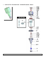
1. VUE ECLATEE - EXPLODED VIEW - SPRENGZEICHNUNG - DIBUJO

SAMES KREMLIN 2 Doc. / Dok. : 574.159.110
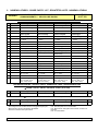
2. NOMENCLATURES - SPARE PARTS' LIST - ERSATZTEILLISTE - NOMENCLATURAS
VOLUREX VANNE DE SORTIE / OUTLET VALVE
AUSGANGSVENTIL / VÁLVULA DE SALIDA
# 107 202
# 107 309
PIECES COMMUNES - COMMON PARTS - GEMEINSAME TEILE - PIEZAS COMUNES
Ind # Désignation Description Bezeichnung Denominación Qté
2 211 552 Porte buse Tip holder Düsehalterung Soporte boquilla 1
* 4 107 287 Chapeau avec siège Cap with seat Oberteil mit Sitz Capucha con asiento 1
*5 155 700 360 Ensemble piston et
porte- aiguille
Needle holder and
piston assembly
Nadelhalterung und
kolben, komplett
Conjunto pistón y
soporte aguja
1
5a NC / NS Porte-aiguille Needle holder Nadelhalterung Soporte aguja 1
5b NC / NS Piston Piston Kolben Pistón 1
6 210 943 Flasque Flange Flansch Brida 1
*7 NC / NS Joint FPM (14x1,78) O ring, FPM (14x1.78) FPM O’Ring (14x1,78) Junta FPM (14x1,78) 2
*8 NC / NS Joint rouge Seal Dichtung Junta 2
*9 NC / NS Joint NBR (44x3) O ring, NBR (44x3) NBR O’Ring (44x3) Junta NBR (44x3) 1
*10 NC / NS Joint NBR (39,64x5,33) Seal, NBR (39.64x5.33) NBR Dichtung
(39,64x5,33)
Junta NBR (39,64x5,33) 1
11 933 151 385 Vis CHc 5x30 Screw, CHc 5x30 Schraube CHc 5x30 Tornillo, CHc 5x30 4
12 210 941 Cylindre Cylinder Zylinder Cilindro 1
13 88 680 Vis 90°, M 5x15 Screw 90°, M 5x15 Schraube 90°, M 5x15 Tornillo 90°, M 5 x 15 1
*14 NC / NS Joint FPM (30x2,5) O ring, FPM FPM O’Ring Junta FPM 2
*15 NC / NS Rondelle Washer Scheibe Arandela 2
*16 NC / NS Circlips Ring Sicherungsring Anillo truarc 2
17 88 139 Vis CHc M6x65 Screw, CHc M6x65 Schraube CHc M6x65 Tornillo, CHc M6x65 4
18 55 260 Raccord coudé
M5 - T 2,5x4
Elbow fitting,
M5 - T 2,5x4
Winkelnippel,
M5 - T 2,5x4
Racor acodado,
M5 - T 2,5x4
2
* 107 203 Pochette de joints
(ind. 7x2, 8x2, 9, 10,
14x2, 15x2, 16x2)
Package of seals
(ind. 7x2, 8x2, 9, 10,
14x2, 15x2, 16x2)
Dichtungssatz
(Pos. 7x2, 8x2, 9, 10,
14x2, 15x2, 16x2)
Bolsa de juntas
(índ. 7x2, 8x2, 9, 10,
14x2, 15x2, 16x2)
1
PIECES SPECIFIQUES - SPECIFIC PARTS - SPEZIFISCHE TEILE - PIEZAS ESPECÍFICAS
VANNE / VALVE / VENTIL / VÁLVULA : AGCR ( # 107 202)
Ind # Désignation Description Bezeichnung Denominación Qté
* 3 203 571 Aiguille Needle Nadel Aguja 1
VANNE / VALVE / VENTIL / VÁLVULA : CR AIG ( # 107 309)
Ind # Désignation Description Bezeichnung Denominación Qté
* 3 211 255 Aiguille monobloc Compact needle Nadel Aguja, tipo monobloque 1
* Pièces de maintenance préconisées.
* Preceding the index number denotes a suggested spare part.
* Bezeichnete Teile sind empfohlene Ersatzteile.
* Piezas de mantenimiento preventivas.
N C : Non commercialisé.
N S : Denotes parts are not serviceable.
N S : Bezeichnete Teile gibt es nicht einzeln, sondern nur
komplett .
N S : no suministrado.

SAMES KREMLIN 3 Doc. / Dok. : 574.159.110
3. DIMENSIONS - ABMESSUNGEN - DIMENSIONES
A
B
CD
E
A B C D E
L (mm) 184 113 Ø 78 Ø 40 M 10x100
L ( " ) 7.24 4.45 3.07 1.57 M 10x100
4. RACCORDEMENTS - FITTINGS - NIPPEL - RACORES
Raccords d'air (Ouverture et fermeture vanne) : Raccord instantané pour tuyau Ø 2,5 x4
Air fittings (Valve opening and closing) : Quick release fitting for hose Ø 2,5 x4
Luftnippel (Öffnungs- und Schließungsventil) : Sofortiger Nippel für Schlauch Ø 2,5 x4
Racores de aire (Apertura y cierre válvula) : Racor instantáneo para tubería Ø 2,5 x4
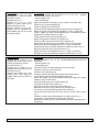
5. MONTAGE - ASSEMBLY - MONTAGE - MONTAJE
MONTAGE DES JOINTS - ASSEMBLY OF THE SEALS - MONTAGE DER DICHTUNGEN - MONTAJE DE LAS JUNTAS
Lors du changement des joints, nous vous recommandons de changer également l'ensemble
piston et porte-aiguille.
When changing the seals, we advice you to change the needle-holder and piston assembly.
Al cambiar las juntas, le aconsejamos cambiar también el conjunto pistón y soporte aguja.

SAMES KREMLIN 4 Doc. / Dok. : 574.159.110
Démontage:
Dévisser les 4 vis (17) pour
désolidariser la vanne de sortie
du doseur Volurex.
Dévisser l'écrou (1).
Dévisser les 4 vis (11) pour
séparer la partie avant de la
partie arrière de la vanne.
Dévisser l'aiguille (3) du porte-
aiguille (5a) en maintenant le
porte-aiguille (5a) par les 2 plats
prévus à cet effet.
Remontage :
Mettre de la graisse sur les joints (7, 8, 9, 15, 16) - (graisse
MAGNALUBE PTFE) et les monter :
- dans le cylindre (12),
- dans le flasque (6),
Mettre de la graisse sur le joint (10) et le monter sur le piston (5b).
Placer la vis (13) dans le flasque (6).
Placer le chapeau sur le flasque (6).
Introduire le porte-aiguille (5a) dans le flasque (6) et le chapeau (4).
Mettre de la colle sur le filetage de l'aiguille (3) - (colle : Loctite 222).
Visser l' aiguille (3) dans le porte-aiguille (5a) en maintenant le porte-
aiguille par les 2 plats prévus à cet effet.
Visser le piston (5b) sur le porte-aiguille (5a).
Mettre de la graisse à l'intérieur du cylindre (12).
Monter la partie avant de la vanne dans le cylindre (12).
Faire tourner le chapeau (4) pour accéder à la vis (13) et la visser.
Mettre de la colle sur le filetage des vis (11) - (colle : Loctite 222)
Fixer la partie avant et la partie arrière de la vanne avec les 4 vis (11).
Monter le porte-buse (2) et serrer avec l'écrou (1).
Mettre de la colle sur le filetage des vis (17) - (colle : Loctite 222).
Remonter la vanne de sortie sur le doseur en vissant les 4 vis (17).
Disassembly :
Unscrew the 4 screws (17) to
separate the outlet valve of the
Volurex proportioning system.
Unscrew the nut (1).
Unscrew the 4 screws (11) to
separate the valve front part from
the valve rear part.
Unscrew the needle (3) of the
needle holder (5a) holding the
needle holder (5a) by means of
the 2 flats.
Assembly :
Grease the seals (7, 8, 9, 15, 16) - (PTFE MAGNALUBE grease) and
install them :
- into the cylinder (12),
- into the flange (6),
Grease the seals (10) and install them on the piston (5b).
Install the screw (13) in the flange (6).
Place the hat on the flange (6).
Insert the needle holder (5a) into the flange (6) and the hat (4).
The needle (3) thread must be glued with Loctite 222.
Screw the needle (3) into the needle holder (5a) holding the needle
holder by means of the 2 flats.
Screw the piston (5b) on the needle holder (5a).
Lubricate the inside of the cylinder (12).
Mount the front part of the valve in the cylinder (12).
Make the hat (4) turn to get to the screw (13) and screw it.
The screws' (11) thread must be glued with Loctite 222.
Fix the front part and the rear part of the valve by means of the 4 screws
(11).
Install the nozzle holder (2) and tighten it by means of the nut (1).
The screws' (17) thread must be glued with Loctite 222.
Reinstall the outlet valve on the proportioning system tightening the 4
screws (17).

SAMES KREMLIN 5 Doc. / Dok. : 574.159.110
Demontage:
Die 4 Schrauben (17)
abschrauben, um das
Ausgangsventil von dem
Dosierungsgerät zu trennen.
Die Mutter (1) abschrauben.
Die 4 Schrauben (11)
abschrauben, um das vorne Teil
des Ventils von dem hinteren Teil
zu trennen.
Die Nadel (3) von der
Nadelhalterung (5a)
abschrauben. Dafür halten Sie
die Nadelhalterung mit den
beiden flachen Zonen.
Montage :
Die Dichtungen (7, 8, 9, 15, 16) fetten - (PTFE-Fett) und dann :
- in das Zylinder (12) montieren,
- in den Flansch (6) montieren.
Die Dichtungen (10) fetten und sie auf den Kolben (5b) montieren.
Die Schraube (13) in den Flansch (6) stellen.
Die Haube auf den Flansch (6) stellen.
Die Nadelhalterung (5a) in den Flansch (6) und in die Haube (4)
einführen.
Klebe auf das Gewinde der Nadel (3) auftragen - (Klebe : Loctite 222).
Die Nadel (3) in die Nadelhalterung (5a) schrauben. Dafür halten Sie die
Nadelhalterung mit den beiden flachen Zonen.
Den Kolben (5b) auf die Nadelhalterung (5a) schrauben.
Die Innenseite des Zylinders (12) fetten.
Das vorne Teil des Ventils in den Zylinder (12) montieren.
Die Haube (4) umdrehen, um die Schraube (13) zu erreichen und sie zu
schrauben.
Klebe auf das Gewinde der Schrauben (11) auftragen - (Klebe : Loctite
222).
Die vorne und Hintere Teile des Ventils mit den 4 Schrauben (11)
befestigen.
Die Düsehalterung (2) montieren und mit der Muttern (1) festschrauben.
Klebe auf das Gewinde der Schrauben (17) auftragen - (Klebe : Loctite
222).
Das Ausgangsventil auf das Dosierungsgerät montieren. Dafür
schrauben Sie die 4 Schrauben (17).
Desmontaje :
Desenroscar los 4 tornillos (17)
para separar la válvula de salida
del dosificador Volurex.
Desenroscar la tuerca (1).
Desenroscar los 4 tornillos (11)
para separar la parte delantera
de la parte trasera de la válvula.
Desenroscar la aguja (3) del
soporte aguja (5a) manteniendo
el soporte aguja (5a) mediante
los 2 planos previstos.
Montaje :
Lubricar las juntas (7, 8, 9, 15, 16) - (Grasa MAGNALUBE PTFE) y
montarlas :
- en el cilindro (12),
- en la brida (6).
Lubricar la junta (10) y montarla en el pistón (5b).
Situar el tornillo (13) en la brida (6).
Posicionar la capucha en la brida (6).
Introducir el soporte aguja (5a) en la brida (6) y la capucha (4).
Aplicar cola en el roscado de la aguja (3) - (cola : Loctite 222).
Roscar la aguja (3) en el soporte aguja (5a) manteniendo el soporte
aguja mediante los 2 planos previstos.
Roscar el pistón (5b) en el soporte aguja (5a).
Lubricar dentro del cilindro (12).
Montar la parte delantera de la válvula en el cilindro (12).
Hacer girar la capucha (4) para acceder al tornillo (13) y roscarlo.
Aplicar cola en el roscado de los tornillos (11) - (cola : Loctite 222).
Fijar la parte delantera y la parte trasera de la válvula con los 4 tornillos
(11).
Montar el soporte boquilla (2) y apretar con la tuerca (1).
Aplicar cola en el roscado de los tornillos (17) -(cola : Loctite 222).
Volver a montar la válvula de salida en el dosificador roscando los 4
tornillos (17).
-
 1
1
-
 2
2
-
 3
3
-
 4
4
-
 5
5
-
 6
6


Sames Volurex outlet valve Benutzerhandbuch
- Typ
- Benutzerhandbuch
in anderen Sprachen
Verwandte Artikel
-
Sames Support assembly for proportioning system Bedienungsanleitung
-
-
-
-
-
-
-
-
-