
Air sampling smoke detection system
AD2-C11 rev.d
Quick Guide for Commissioning
1 Installation
§ Connect power (24VDC)
§ Connect the detector lines
§ Connect reset input (if S3 = ON)
§ Install the detector bases and the smoke detectors
§ Prepare for operation with 1 or 2 pipe systems
§ Connect pipe system or test pipe
2 Set Up
Set DIP switches S2 on pcb E596 according to tables below:
Air flow monitoring
Switch S2 delay time Switch S2 Range
A(1) B(2) C(3) D(4)
OFF
ON
short 30 s
ON
OFF small I
ON
OFF middle 2 min. (standard) OFF
ON
middle II
ON ON
long 15 min.
OFF OFF large III (standard)
OFF OFF very long 1 h
ON ON
very large IV
Fault
Switch S3
OFF Fault not latching (standard)
ON
Fault latching until reset
Atmospheric pressure compensation
R28 MP1 (+) MP2 (-) see correction table for atm.pressure or 2,50 V (standard)
3 Commissioning
Initializing of airflow monitoring
1. press button S1 “Init” several times:
for 1 tube system:
for 2 tube systems:
green LED and yellow LED left flashes
green LED und yellow LEDs left and right flashes
2. Fix cover and tighten screws within the next 2 min.
3. Initialization active ca. 20 min., green and yellow LED flashing
4. Unit ready green LED on
Fire & Security Products
Siemens Building Technologies Group

Siemens Building Technologies AG
Alte Landstrasse 411
CH-8708 Männedorf
Tel. +41 1 - 922 61 11
Fax +41 1 - 922 64 50
www.cerberus.ch
Document no. e4161b Manual -
Edition 07.2001 Section -
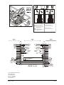
Betrieb mit 1 Rohrsystem
LS1 LS1LS2 LS2
LSx Luftstromsensor Nr. x
Öffnun
g
verschlossen mit
Membrandurchführun
g
stülle
Öffnung unverschlossen
Blindstopfen
Betrieb mit 2 Rohrsystemen
Standardanordnung der
Membrandurchführungstüllen
1 1
2 2
3 3
4 45 5
Operation with 1 pipe system
LSx air flow sensor no. x
opening closed with
membrane leadthrough socket
opening unclosed
blind plug
Operation with 2 pipe systems
standard design of the
membrane leadthrough sockets
1
2
3
4
5
6
7
8
9
10
11
12
13
14
15
16
17
18
1
2
3
4
5
6
7
8
9
10
11
12
13
14
15
16
internalexternal
X1
Störung 1
Fault 1
(normal)
(gestört)
(fault)
X2
+ Reset
- Reset
Rückstellen
Reset
Speisung
Supply
24 VDC
A
D2-C1
1
external
L2-
L2-
L1-
L2+
L1+
L2+
L1+
L1-
Detector+
Detector-
Detector+
Detector-
+ext. Alarm
-ext. Alarm
Störung 2
Fault 2
(normal)
(gestört)
(fault)
Detector-Detector-
B
C
A
B
C
A
0V
+24V
0V
+24V
0V
+24V
-
 1
1
-
 2
2


in anderen Sprachen
- English: Siemens AD2-C11
Andere Dokumente
-
Maico WRG 35 Mounting And Operating Instructions
-
 BlueWalker PowerWalker VI 1500RT LCD/UK Benutzerhandbuch
-
Honeywell 805595 Benutzerhandbuch
-
 Domotec DSG12 Datenblatt
-
Chamberlain TST-2 Bedienungsanleitung
-
 PowerWalker VFI 1500RT Benutzerhandbuch
-
CAB Apollo Benutzerhandbuch
-
-
Cooper MBD100R Benutzerhandbuch


