Rutenbeck Control Plus IP4 Installationsanleitung
- Typ
- Installationsanleitung

Montageanleitung / Installation instructions
Safety Information
Legal Information
These instructions contain information such as important remarks and
warnings that, if not observed, can lead to serious personal injuries or
system damage. Please ensure that you read these instructions carefully
before commissioning the switch actuator/sensor and signalling device
-Control Plus IP 4 (subsequently referred to as IP 4).
The correct transport, storage and installation as well as careful opera-
tion and maintenance of the device are decisive for safe operation of the
device.
Power supply
The IP 4 has been designed for 230 V operation.
Work on the power supply network may only be performed by
authorised electricians.
Risk to life from electric current. Ensure that the power supply
is disconnected before performing any assembly work.
Housing temperature
The overall current to all four outputs may not exceed a total of 40A
during operation within the approved temperature range of up to 40°C.
The permissible overall current is 20 A for two adjacent outputs.
Intended use
The IP 4 may only be used according to the descriptions contained in the
instructions. The device may only be used provided that it is in a flawless
condition and in the stated ambient conditions. Do not use the device for
any other purpose and ensure that it is only used indoors.
All specifications and supplied software versions are subject
to change without notice. Please check www.rutenbeck.de
for the latest documents and software versions of the device.
In accordance with the current data privacy guidelines, ensure
that only authorised personnel is given access to the device or
the connected network.
Only use certified cables. Other cables may cause malfunctions
or lead to the destruction of the devices.
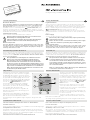
General Information
The device is a universal, IP-based switching
and signalling device. The 230 V connection is
provided via the removable plug terminal (F) with
two labelled terminal contacts. Also the connec-
tion of the potential-free switching outputs via
the terminals (E). The side female connector strip
(C) allows the connection of
-Control Plus
additional devices such as the
-Control
Plus-Extension.
Connection of the analog 0–10 V or 4–20mA
sensor input takes place via the screw plug
terminal (A), also the connection of potential-free
contacts via the terminals (B).
The Connection to the network takes place via
the RJ45 socket with integrated LED display (H)
for network functions.
The device can be restarted or reset to factory
settings or the internal API interface can be ena-
bled via the reset button (G).
All settings and programming take place via the integrated web interface.
License notices/code
Part of this firmware is subject to third-party licences.
License information
This product contains software from third parties with licence conditions.
Availability of the source codes
Upon request, we will send you the entire source code of the GNU Gen-
eral Public License licensed software - including all scripts to control the
compilation and installation of the drivers. Full details of the licenses can
be found in a separate document.
Please go to www.rutenbeck.de for more information.
Sicherheitshinweise
Rechtliche Hinweise
Diese Anleitung enthält u.a. wichtige Anmerkungen und Warnungen,
deren Nichtbeachtung zu ernsthaften Personen- oder Anlageschä-
den führen kann. Bitte lesen Sie die Anleitung vor Inbetriebnahme des
Schaltaktor/-sensors und Meldegerätes
-Control Plus IP 4 (im fol-
genden IP 4) aufmerksam durch. Ordnungsgemäßer Transport, korrekte
Lagerung und Installation sowie sorgfältige Bedienung und Instandhaltung
der Ge räte sind entscheidend für den sicheren Betrieb.
Spannungsversorgung
Der IP 4 wurde für den Betrieb mit 230 V konzipiert.
Arbeiten am Versorgungsnetz dürfen nur von autorisiertem
Elektrofachpersonal ausgeführt werden!
Lebensgefahr durch elektrischen Strom! Bei allen Montage -
arbeiten schalten Sie zunächst die Netzspannung frei.
Gehäusetemperatur
Für einen Betrieb im zugelassenen Temperaturbereich bis 40°C darf
der Gesamtstrom an allen vier Ausgängen in Summe 40 A nicht über-
schreiten. Für zwei nebeneinander liegende Ausgängen beträgt der
zulässige Gesamtstrom 20 A.
Bestimmungsgemäßer Gebrauch
Der IP 4 darf nur wie in der Anleitung beschrieben verwendet werden. Er
darf nur unbeschädigt und unter den angegebenen Umweltbedingungen
eingesetzt werden. Betreiben Sie das Gerät zu keinem anderen Zweck
und nur in Innenräumen.
Alle Spezifikationen und mitgelieferte Software-Versionen
können ohne vorherige Ankündigung geändert werden.
Bitte informieren Sie sich auf www.rutenbeck.de über die
aktuellen Dokumente und Software-Versionen des Gerätes.
Stellen Sie im Sinne der aktuellen Datenschutzrichtlinien sicher,
dass nur autorisiertes Personal Zugang zu dem Gerät bzw. dem
angeschlossenen Netzwerk hat. Verwenden Sie nur zertifizierte
Kabel. Andere Kabel können Fehlfunktionen verursachen oder
zur Zerstörung der Geräte führen.
Allgemeines
Das Gerät ist ein universelles, IP-basiertes Schalt-
und Meldegerät. Der 230 V Anschluss erfolgt über
die abziehbare Steckklemme (F) mit zwei gekenn-
zeichneten Steckkontakten – ebenso der Anschluss
der potentialfreien Schaltausgänge über die Klem-
men (E). Die seitliche Buchsenleiste (C) erlaubt den
Anschluss von
-Control Plus-Zusatzge räten
wie z. B. der
-Control Plus Extension.
Der Anschluss des analogen Sensoreinganges
0–10 V oder 4–20mA erfolgt über die Schraub-
Steckklemme (A), ebenso der Anschluss potential-
freier Kontakte über die Klemmen (B).
Die Anbindung an das Netzwerk erfolgt über die
RJ45-Buchse mit integrierter LED-Anzeige (H) für
Netzwerkfunktionen.
Über den Reset-Knopf (G) läßt sich das Gerät neu
starten oder auf Werkseinstellungen zurücksetzen
bzw. die interne API-Schnittstelle freischalten.
Alle Einstellungen und Programmierungen erfolgen per integriertem Web-
Interface.
Lizenzhinweise/Quellcode
Teile der Firmware unterliegen der Lizenz von Drittanbietern.
Lizenzinformationen
Dieses Produkt enthält Software von Drittanbietern mit Lizenzbedingungen.
Verfügbarkeit des Quellcodes
Auf Anfrage senden wir Ihnen den gesamten Quellcode der lizenzierten
Software zu – einschließlich aller Scripts, um die Kompilierung und Instal-
lation der Treiber zu steuern. Die vollständigen Angaben zu den Lizenzen
finden Sie in separaten Dokumenten.
Informationen hierzu finden Sie auf www.rutenbeck.de
Technical Support
+49 23 5 5 82-111
Commercial Support
+49 2355 82-137
1
F
A
E
B
D
H
G
C
I

LED
Die LEDs (D, H und I) haben folgende Bedeutung:
LED und Farbe Zustand Bedeutung
1–4
(D)
grün
- leuchtet
- leuchtet nicht
Schaltausgang eingeschaltet
Schaltausgang ausgeschaltet
RJ45
(H)
grün
- leuchtet
- blinkt schnell
(ungleichmäßig)
- flackert
(gleichmäßig)
- blinkt abwech-
selnd mit LED R
Keine Netzwerkverbindung
Anzeige Link Aktivität
Neustart des Gerätes
Freigabe der API
R
(I)
orange
- blinkt (Herzschlag)
- flackert
(gleichmäßig)
- blinkt abwech-
selnd mit LED RJ45
Normalfunktion
Laden der Werkseinstellungen
Freigabe der API
Installation
Anschließen der Netzspannung
Lebensgefahr! Schalten Sie die Netz-
spannung vor dem Anschließen frei.
Beachten Sie bei Arbeiten in und an elektri-
schen Anlagen die fünf Sicherheitsregeln nach
DIN VDE 0105:
1 Freischalten
2 Gegen Wiedereinschalten sichern
3 Spannungsfreiheit allpolig feststellen
4 Erden und kurzschließen
5 Benachbarte unter Spannung stehende Teile
abdecken.
Beachten Sie die Anschlussbilder 2 sowie 3 und
schließen Sie die Netzspannung sowie die Schalt-
ausgänge (Leiterquerschnitt maximal 2,5mm
2
)
mittels Klemmblock (F und E) entsprechend an.
Die Klemmen der Sensoreingänge (A und B) sind
für einen Leiterquerschnitt von max. 1,5 mm
2
vorgesehen. Die Länge der Sensorleitung darf
100m nicht überschreiten. Für den vereinfach-
ten Anschluss verwenden Sie die
-Control
Plus Adapter NTC (Temperaturmessung) oder
4–20 mA (2-Leiter Sensoradapter).
Um eine Beeinflussung des Netzwerks durch
Störungen/Veränderungen im Bereich der 230 V
Installation zu vermeiden, trennen Sie stets die
Spannungsversorgung aktiver Komponenten
sowie der Datenendgeräte (PC usw.) von denen
anderer Verbraucher (z. B. Mikrowelle, Staubsauger).
Verwenden Sie eigene Stromkreise, indem Sie z. B. einen Leitungstrenn-
oder -schutzschalter einsetzen und ggf. einen geeigneten Überspan-
nungsschutz (C-Ableiter). Kennzeichnen Sie den Stromkreis sowie die
zugehörigen Steckdosen eindeutig, z. B. mit ‚EDV/DATA‘.
Update Firmware
Werkauslieferung
Bei Auslieferung ab Werk ist das Gerät mit der jeweils aktuellen Firmware
ausgestattet. Durch Lagerung und Handelszyklen bedingt, kann es zwi-
schenzeitlich neuere Versionen der Firmware geben.
Führen Sie ein Update durch, damit Ihr Gerät mit der neusten Firmwa-
re ausgestattet ist. Nur so ist ein ordnungsgemäßer Betrieb gesichert.
Konfiguration
Für individuelle Einstellungen verbinden Sie nun den IP 4 über ein Patch-
kabel mit der LAN-Schnittstelle Ihres PCs und konfigurieren Sie ihn nach
Ihren Wünschen.
Sie erreichen das Gerät unter der
IP-Adresse: http://192.168.0.6
Password: admin
Individualisieren Sie sofort bei der Erstkonfiguration mindestens
das Passwort und den Key.
Eine aktuelle, detaillierte Bedienunsgs anleitung erhalten Sie im Download-
Bereich der Rutenbeck Homepage unter www.rutenbeck.de
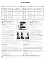
LED
The LEDs (D, H and I) have the following meaning:
LED and colour State Meaning
1–4
(D)
green
- lights on
- off
switching output on
switching output off
RJ45
(H)
green
- lights on
- flashes quickly
(unevenly)
- flicker
(evenly)
- flashes alternately
with LED R
no network connection
shows link activity
restarting the device
unblocking of the API
R
(I)
orange
- flashing (heartbeat)
- flicker
(evenly)
- flashes alternately
with LED RJ45
normal mode
loading the factory settings
unblocking of the API
Installation
Power supply connection
Danger to life! Isolate the power
supply prior to connection.
Follow the five safety rules according to DIN
VDE 0105 when working in and on electrical
plants.
1 Isolate
2 Secure against restart
3 Determine that the equipment is not live on
all poles
4 Earth and short-circuit
5 Cover or cordon off adjacent parts that are live.
Please refer to connection diagrams 2 and 3,
and connect the mains voltage and also the
switched outputs (core cross-section max-
imum 2.5mm
2
) using the terminal blocks (F
and E) appropriately. The terminals for the sen-
sor inputs (A and B) are designed for a core
cross-section of max. 1.5mm
2
. The sensor
cable length may not exceed 100 m.
For simplified connection, use the
-Control
Plus Adapter NTC (temperature measurement) or
4–20mA (2-wire sensor adapter).
In order to prevent network impact caused by
disturbances/changes in the area of the 230 V
installation, always disconnect the power supply
to active components as well as data end devices
(PC, etc.) from those to other consumers (e. g.
microwave, vacuum cleaner).
Always use independent circuits by utilising circuit breakers or circuit
switches and, where necessary, a suitable surge protection device
(C-conductor) for instance. Clearly label the circuit as well as the associat-
ed sockets, e.g. ‘EDP/DATA’.
Firmware update
Works delivery
When delivered from the works the device is provided with the up-to-date
firmware valid at that time. Storage and trade cycles mean that it is possi-
ble that new versions of the firmware are available. You should carry out
a firmware update so that your device has the newest firmware ver-
sion installed. This is the only way to guarantee proper operation.
Configuration
For individual settings, now connect the IP 4 to the LAN interface on your
PC using a patch cable and then configure it to your requirements.
You can access the device using the
IP address: http://192.168.0.6
Password: admin
During the initial configuration you should immediately
individualise at least the password and the key.
You can find an up-to-date, detailed operating manual in the download
area of the Rutenbeck homepage at www.rutenbeck.de
230 V
IP 4
A1
01L N 02 03 04
I1
1R 2 3 4
I2 I3 I4 I5 I6
2
3
F
Sen-
sor
A1 I1
Sen-
sor
A1 I1
A1 I1 I2
Sensor
0 – 10 V
Sensor
4 – 20 mA
Digitale Eingän-
ge / digital inputs

Reset
Um das Gerät neu zu starten, drücken Sie den Reset-Knopf (G) für ca.
acht bis zwölf Sekunden. Während des nachfolgenden Neustarts blinkt
die LAN-LED in der RJ45-Buchse (H). Bei Betriebsbereitschaft blinkt die
orangene LED im Sekundentakt (Herzschlag).
Um das Gerät auf Werkseinstellungen mit zugehöriger Firmware zurück-
zusetzen, drücken Sie den Reset-Knopf für ca. 18 bis 100 Sekunden.
Während des Neustarts flackert die orangene LED (I). Bei Betriebsbereit-
schaft blinkt die orangene LED im Sekundentakt (Herzschlag).
Um die API freizuschalten, drücken Sie den Reset-Knopf zwischen ein
bis fünf Sekunden. Die orangene LED und die LAN-LED (in der RJ45-
Buchse) blinken abwechselnd für 60 Sekunden. Die API-Schnittstelle kann
alternativ einmalig in der Systemsteuerung freigeschaltet werden.
CE-Erklärung
Wir, die Wilhelm Rutenbeck GmbH & Co. KG erklären in unserer
alleinigen Verantwortung, dass sich dieses Gerät in Übereinstim-
mung mit den grundlegenden Anforderungen und relevanten Vor-
schriften der zutreffenden EU-Richtlinien 2014/30/EU, 2014/53/EU,
2011/65/EU) befindet.
Die vollständige CE-Konformitätserklärung finden Sie unter
www.rutenbeck.de im Download-Bereich.
Entsorgung
Das nebenstehende Symbol weist auf die getrennte Sammlung
von Elektro- und Elektronikgeräten hin. Dieses Gerät sowie alle
im Lieferumfang enthaltenen Elektronikteile dürfen gemäß euro-
päischer Richtlinien und deutschem Elektro- und Elektronikgesetz
nicht über den Hausmüll entsorgt werden.
Bringen Sie dieses Gerät nach Ende seiner Nutzung zu einem
zuständigen Sammelsystem für elektrische und elektronische
Altgeräte.
Technische Daten
Reset
To restart the device, press the reset button (G) for about eight to twelve
seconds. During the following restart, the LAN LED in the RJ45 socket (H)
flashes. When ready for operation, the orange LED flashes every second
(heartbeat).
To reset the device to factory settings with the associated firmware, press
the reset button for approx. 18 to 100 seconds. During the restart the
orange LED (I) flickers. When ready for operation, the orange LED flashes
every second (heartbeat).
To unlock the API, press the reset button between one to five seconds.
The orange LED and the LAN LED (in the RJ45 socket) flash alternately
for 60 seconds. The API interface can alternatively be enabled once in the
Control Panel.
CE - Declaration of confirmity
We, Wilhelm Rutenbeck GmbH & Co. KG, declare under our sole
responsibility that this device is in conformity with the essential
requirements and the relevant regulations of the applicable EU-
directives (2014/30/EU, 2014/53/EU, 2011/65/EU).
The complete Declaration of Conformity is available in the Download Sec-
tion at www.rutenbeck.com
Disposal
The adjacent symbol indicates separate waste collection for elec-
trical and electronic devices. In accordance with EU-directives,
all electrical and electronic devices with this symbol must be dis-
posed in the corresponding separate waste collections and not in
the domestic waste.
This device as well as all the electronic parts included in the delivery
may not be disposed in the regular household waste but must be
brought to a competent collection site after end of its use.
Technical Data
-Control Plus IP 4
Schutzart Polyamid / Polyamide (PA 6/6.6), IP20 Protection Class
Betriebstemperatur -5 bis / to +40 °C Operating temperature
Lagertemperatur -40 bis / to +85 °C Storage temperature
Digitaleingänge 5 V DC für potenzialfreie Kontakte Digital inputs
Anschlüsse
Anschluss Spannungsversorgung 1 x 2-polig, schraubenlose Steckklemme /
connection mains supply 1 x 2-pole, screwless plug terminal
Anschluss Relaisausgänge 4 x 2-polig, schraubenlose Steckklemmen /
connection relay outputs 4 x 2-pole, screwless plug terminals
Anschluss A/D Eingänge 1 x 3-polig, Schraub-/Steckklemme /
connection A/D inputs 1 x 3-pole, screw/plug terminal
Anschluss digitale Eingänge 3 x 4-polig, Schraub-/Steckklemmen /
connection digital inputs 3 x 4-pole, screw/plug terminal
1 x RJ45 Buchse / port
Connections
Spannungsversorgung /
Relaisausgänge
Leiterquerschnitt max. 2,5 mm
2
/ Cable diameter max. 2.5 mm
2
Power supply/
relay outputs
Sensoreingänge Leiterquerschnitt max. 1,5 mm
2
/ Cable diameter max. 1.5 mm
2
Sensor input
Ethernet IEEE 802.3U 100Base-TX / 10Base-TX Ethernet
Kontaktbelastung
je / each 230 V / 16 A, cos j = 1,0
je / each 230 V / 15 A, cos j = 0,8
je / each 230 V / 14 A, cos j = 0,6
je / each 230 V / 11 A, cos j = 0,4
je / each 230 V / 6 A, cos j = 0,2
max. 40 A Gesamtstrom bei 40 °C / max. 40 A total current at 40 °C
max. 20 A bei benachbarten Kontakten / max. 20 A joining contacts
Contact load
Spannungsversorgung 230 V 100–240 V / 50–60Hz / 40 mA – 18 mA Power supply 230 V
Leistungsaufnahme max. 4 VA Power consumption
Luftfeuchtigkeit 5–95 % rHd nicht kondensierend / non-condensing Humidity
Abmessungen H x B x T / H x W x D: 90 x 72 x 59 mm (4 TE) Dimensions
Gewicht 310 g Weight

Klagebach 33
D-58579 Schalksmühle
Telefon +49-(0) 23 55-82-0
Telefax +49-(0) 23 55-82-105
www.rutenbeck.de
© Wilhelm Rutenbeck GmbH & Co. KG · Technische Änderungen vorbehalten/Subjected to technical changes · 293 824 · 700 802 615 · Rut083 · Stand/Status 09.20
-
 1
1
-
 2
2
-
 3
3
-
 4
4


Rutenbeck Control Plus IP4 Installationsanleitung
- Typ
- Installationsanleitung
in anderen Sprachen
Verwandte Artikel
-
Rutenbeck 700802615 - R-Control Plus IP 4 Benutzerhandbuch
-
-
-
-
-
-
-
-
-
Andere Dokumente
-
Axis A1001 Benutzerhandbuch
-
Axis Communications Q7424-R Benutzerhandbuch
-
AJA IPR-10G2-SDI Benutzerhandbuch
-
Avigilon ENC-4P-H264 Installationsanleitung
-
AVENTICS Bus Coupler AES/Valve Driver AV CANopen Benutzerhandbuch
-
Axis AXIS P1354 Benutzerhandbuch
-
Mettler Toledo IND780 (11 MB) Installationsanleitung
-
sauter EY6CM30 Benutzerhandbuch
-
-
DAB DCONNECT BOX Bedienungsanleitung