Rutenbeck 700802612 - R-Control Plus Extension 4 Benutzerhandbuch
- Typ
- Benutzerhandbuch

Extension 4
Montageanleitung / Installation instructions
Safety Information
Legal Information
These instructions contain informations such as important remarks and
warnings that, if not observed, can lead to serious personal injuries or
system damage. Please ensure that you read these instructions carefully
before commissioning the -Control Plus Extension 4 (subsequently
referred to as extension). The correct transport, storage and installation as
well as careful operation and maintenance of the device are decisive for
safe operation of the device.
Power supply
The extension has been designed for 230 V operation.
Work on the power supply network may only be performed by
authorised electrician!
Risk to life from electric current! Ensure that the power supply
is disconnected before performing any assembly work.
Housing temperature
The total current at all four switching outputs must not exceed 40A
for operation in the approved temperature range up to 40°C.
The permissible overall current is 20A for two adjacent outputs.
Intended use
The extension may only be used according to the descriptions contained
in the instructions. The device may only be used provided that it is in a
flawless condition and in the stated ambient conditions.
Do not use the device for any other purpose and ensure that it is only
used indoors.
The extension may still only be used in conjunction with the
-Control Plus IP 4 or IP 8. Firmware version 3.0.0.0 or
higher must be installed on these devices. The corresponding
-Control App must be up to date.
All specifications and supplied software versions are subject
to change without notice. Please check www.rutenbeck.de
for the latest documents and software versions of the device.
In accordance with the current data privacy guidelines, ensure
that only authorised personnel is given access to the device or
the connected network.
Only use certified cables. Other cables may cause malfunctions
or lead to the destruction of the devices.
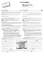
General Information
The Extension is a universal, IP-based device for
functional extension of the -Control Plus IP4
or IP8 switching and signaling devices.
The 230 V connection is provided via the remov-
able plug terminal (B) with two labelled terminal
contacts. The device has four analogue outputs
0–10 V (A) which can be used for dimming func-
tions, for example.
An additional four outputs (C) are designed for up
to 16A, 230V each. These can be operated in
pairs (e.g. AO1 with OA1) or can be used as sep-
arate, potential-free switch extensions.
The extension is connected to a network exclu-
sively via an -Control Plus IP4 or IP8. For
this purpose the extension is connected via the
lateral plug contacts (D).
All settings and programming are carried out exclusively via the integrated
web interface on the connected -Control Plus IP4 or IP8.
Sicherheitshinweise
Rechtliche Hinweise
Diese Anleitung enthält u.a. wichtige Anmerkungen und Warnungen,
deren Nichtbeachtung zu ernsthaften Personen- oder Anlageschäden
führen kann. Bitte lesen Sie die Anleitung vor Inbetriebnahme der
-Control Plus Extension 4 (im folgenden Extension) aufmerksam
durch. Ordnungsgemäßer Transport, korrekte Lagerung und Installation
sowie sorgfältige Bedienung und Instandhaltung der Ge räte sind entschei-
dend für den sicheren Betrieb.
Spannungsversorgung
Die Extension wurde für den Betrieb mit 230 V konzipiert.
Arbeiten am Versorgungsnetz dürfen nur von autorisiertem
Elektrofachpersonal ausgeführt werden!
Lebensgefahr durch elektrischen Strom! Bei allen Montage-
arbeiten schalten Sie zunächst die Netzspannung frei.
Gehäusetemperatur
Für einen Betrieb im zugelassenen Temperaturbereich bis 40°C darf
der Gesamtstrom an allen vier Schaltausgängen in Summe 40A nicht
überschreiten. Für zwei nebeneinander liegende Ausgängen beträgt
der zulässige Gesamtstrom 20A.
Bestimmungsgemäßer Gebrauch
Die Extension darf nur wie in der Anleitung beschrieben verwendet werden.
Es darf nur unbeschädigt und unter den angegebenen Umweltbedingun-
gen eingesetzt werden. Betreiben Sie das Gerät zu keinem anderen
Zweck und nur in Innenräumen.
Die Extension darf weiterhin nur in Verbindung mit dem
-Control Plus IP 4 bzw. IP 8 eingesetzt werden.
Auf diesen Ge räten muss mindestens die Firmware Version
3.0.0.0 auf gespielt sein. Die zugehörige -Control App
muss auf dem neusten Stand sein.
Alle Spezifikationen und mitgelieferte Software-Versionen
können ohne vorherige Ankündigung geändert werden.
Bitte informieren Sie sich auf www.rutenbeck.de über die
aktuellen Dokumente und Software-Versionen des Gerätes.
Stellen Sie im Sinne der aktuellen Datenschutzrichtlinien sicher,
dass nur autorisiertes Personal Zugang zu dem Gerät bzw. dem
angeschlossenen Netzwerk hat. Verwenden Sie nur zertifizierte
Kabel. Andere Kabel können Fehlfunktionen verursachen oder
zur Zerstörung der Geräte führen.
Allgemeines
Die Extension ist ein universelles, IP-basiertes
Gerät zur Funktionserweiterung der Schalt- und
Meldegeräte -Control Plus IP4 bzw. IP8.
Der 230 V Anschluss erfolgt über die abziehbare
Steckklemme (B) mit zwei gekennzeichneten
Steckkontakten. Das Gerät besitzt vier analoge
Ausgänge 0–10V (A), die zum Beispiel für Dimm-
funktionen genutzt werden können.
Weitere vier Ausgänge (C) sind für jeweils bis zu
16A, 230V ausgelegt. Diese können paarweise
gekoppelt (z. B. AO1 mit OA1) betrieben werden
oder als separate, potentialfreie Schalterweite-
rung dienen.
Die Anbindung der Extension an ein Netzwerk
erfolgt ausschließlich über einen -Control
Plus IP4 bzw. IP8. Hierzu wird die Extension
über die seitlichen Steckkontakte (D) angebunden. Alle Einstellungen und
Programmierungen erfolgen ausschließlich per integriertem Web-Interface
des angebundenen -Control Plus IP4 bzw. IP8.
Technical Support
+49 235 5 82-111
Commercial Support
+49 2355 82-137
1
B
A
C
D

Installation
Anschließen der Netzspannung
Lebensgefahr! Schalten Sie die Netzspannung vor dem
Anschließen frei.
Beachten Sie bei Arbeiten in und an elektrischen Anlagen die fünf
Sicherheitsregeln nach DIN VDE 0105:
1 Freischalten
2 Gegen Wiedereinschalten sichern
3 Spannungsfreiheit allpolig feststellen
4 Erden und kurzschließen
5 Benachbarte unter Spannung stehende Teile
abdecken.
Beachten Sie das Anschlussbild 2 (exemplarisch
zusammen mit dem -Control Plus IP 4 darge-
stellt) und schließen Sie die Netzspannung sowie
die Schaltausgänge (Leiterquerschnitt maximal
2,5mm2) entsprechend an.
Achten Sie beim Zusammenstecken der Geräte
auf eine parallele Positionierung der Steckverbin-
derkontakte (D), so dass diese nicht verbogen
werden.
Führen Sie die Anschlussleitungen der analogen
Ausgänge AO1–AO4 so kurz wie möglich aus.
Dies vermeidet gegebenenfalls Fehlfunktionen
der Peripheriegeräte durch Spannungsabfall auf
der Leitung.
Um eine Beeinflussung des Netzwerks durch
Störungen/Veränderungen im Bereich der 230 V
Installation zu vermeiden, trennen Sie stets die
Spannungsversorgung aktiver Komponenten
sowie der Datenendgeräte (PC usw.) von denen
anderer Verbraucher (z. B. Mikrowelle, Staubsauger).
Verwenden Sie eigene Stromkreise, indem Sie
z. B. einen Leitungstrenn- oder -schutzschalter
einsetzen und ggf. einen geeigneten Überspan-
nungsschutz (C-Ableiter). Kennzeichnen Sie den
Stromkreis sowie die zugehörigen Steckdosen
eindeutig, z. B. mit ‚EDV/DATA‘.
Weitere exemplarische Anschlussmöglichkeiten
finden Sie in den Abbildungen 3 und 4.
Konfiguration
Für individuelle Einstellungen folgen Sie, nach-
dem die Extension mit dem -Control Plus
IP 4 bzw. IP 8 verbunden ist, den Anleitungen
zum -Control Plus IP4 bzw. IP8.
Installation
Power supply connection
Danger to life! Isolate the power supply prior to connection.
Follow the five safety rules according to DIN VDE 0105 when working
in and on electrical plants.
1 Isolate
2 Secure against restart
3 Determine that the equipment is not live on all poles
4 Earth and short-circuit
5 Cover or cordon off adjacent parts that are live.
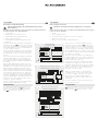
Please refer to connection diagram 2 (shown
exemplarily together with the -Control Plus
IP4) and connect the mains voltage and also the
switched outputs (core cross-section maximum
2.5mm2) using the terminal blocks appropriately.
When plugging the devices together, ensure that
the connector contacts (D) are positioned parallel
so that they are not bent.
Keep the connection cables for the analog out-
puts AO1–AO4 as short as possible. This avoids
possible malfunctions of the peripheral devices
due to voltage drop on the line.
In order to prevent network impact caused by
disturbances/changes in the area of the 230 V
installation, always disconnect the power supply
to active components as well as data end devices
(PC, etc.) from those to other consumers (e.g.
microwave, vacuum cleaner).
Always use independent circuits by utilising
circuit breakers or circuit switches and, where
necessary, a suitable surge protection device
(C-conductor) for instance. Clearly label the
circuit as well as the associated sockets, e.g.
‘EDP/DATA’.
For further example connection options please
refer to Figures 3 and 4.
Configuration
For individual settings follow the instructions for
-Control Plus IP4 or IP8 after the extension
is connected to -Control Plus IP4 or IP8.
230 V
IP 4
A1 A2
01L N 02 03 04
I1
1R 2 3 4
I2 I3 I4 I5 I6
Extension 4
AO1 AO2 AO3 AO4
OA1 OA2 OA3 OA4 L N
+ – + – + – + –
2
230 V
IP 4
A1 A2
01L N 02 03 04
I1
1R 2 3 4
I2 I3 I4 I5 I6
Extension 4
AO1 AO2 AO3 AO4
OA1 OA2 OA3 OA4 L N
+ – + – + – + –
L N
–
0–10 V
+ +
LED
rot
–
LED-Controller
LED
3
230 V
IP 4
A1 A2
01L N 02 03 04
I1
1R 2 3 4
I2 I3 I4 I5 I6
Extension 4
AO1 AO2 AO3 AO4
OA1 OA2 OA3 OA4 L N
+ – + – + – + –
–
0–10 V
+
DALI-Converter
GND
DALI (10 mA)
24 V
GND
24 V
N
PE
L1
L2
N
PE
L1
4
Anschluss/Montage
Connection/assembly
LED-Dimmen mit 0-10 V LED-Controller
LED dimming with 0-10 V LED controller
Ansteuerung eines DALI-Gateways
Actuation of a DALI gateway

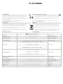
CE-Erklärung
Wir, die Wilhelm Rutenbeck GmbH & Co. KG erklären in unserer
alleinigen Verantwortung, dass sich dieses Gerät in Übereinstim-
mung mit den grundlegenden Anforderungen und relevanten Vor-
schriften der zutreffenden EU-Richtlinien 2014/30/EU, 2014/53/EU,
2011/65/EU) befindet.
Die vollständige CE-Konformitätserklärung finden Sie unter
www.rutenbeck.de im Download-Bereich.
Entsorgung
Das nebenstehende Symbol weist auf die getrennte Sammlung
von Elektro- und Elektronikgeräten hin. Dieses Gerät sowie alle
im Lieferumfang enthaltenen Elektronikteile dürfen gemäß euro-
päischer Richtlinien und deutschem Elektro- und Elektronikgesetz
nicht über den Hausmüll entsorgt werden.
Bringen Sie dieses Gerät nach Ende seiner Nutzung zu einem
zuständigen Sammelsystem für elektrische und elektronische
Altgeräte.
Technische Daten
CE - Declaration of confirmity
We, Wilhelm Rutenbeck GmbH & Co. KG, declare under our sole
responsibility that this device is in conformity with the essential
requirements and the relevant regulations of the applicable EU-
directives (2014/30/EU, 2014/53/EU, 2011/65/EU).
The complete Declaration of Conformity is available in the Download
Section at www.rutenbeck.com
Disposal
The adjacent symbol indicates separate waste collection for elec-
trical and electronic devices. In accordance with EU-directives,
all electrical and electronic devices with this symbol must be dis-
posed in the corresponding separate waste collections and not in
the domestic waste.
This device as well as all the electronic parts included in the delivery
may not be disposed in the regular household waste but must be
brought to a competent collection site after end of its use.
Technical Data
-Control Plus Extension 4
Schutzart Polyamid / Polyamide (PA 6/6.6), IP20 Protection Class
Betriebstemperatur -5 bis / to +40 °C Operating temperature
Lagertemperatur -40 bis / to +85 °C Storage temperature
Analogausgänge 0 / 1 V–10 V DC, parametrierbar / parameterisable (max. 0,4 W / Port) Analogue outputs
Anschlüsse
Spannungsversorgung / connection mains supply
1x 2-polig, schraubenlose Steckklemme / 1x 2-pole, screwless plug terminal
Relaisausgänge / relay outputs
4x 2-polig, schraubenlose Steckklemmen / 4x 2-pole, screwless plug terminals
Analogausgänge / connection analogue outputs
4x 2-polig, schraubenlose Steckklemmen / 4x 2-pole, screwless plug terminals
Connections
Kontaktbelastung
je / each 230 V / 16 A, cos j = 1,0
je / each 230 V / 15 A, cos j = 0,8
je / each 230 V / 14 A, cos j = 0,6
je / each 230 V / 11 A, cos j = 0,4
je / each 230 V / 6 A, cos j = 0,2
max. 40 A Gesamtstrom bei 40 °C / max. 40 A total current at 40 °C
max. 20 A bei benachbarten Kontakten / max. 20 A joining contacts
Contact load
Spannungsversorgung /
Relaisausgänge Leiterquerschnitt max. 2,5 mm2 / Cable diameter max. 2.5 mm2Power supply/
relay outputs
Spannungsversorgung 230 V 100–240 V / 50–60Hz / 100 mA – 42 mA Power supply 230 V
Leistungsaufnahme max. 4,5 VA Power consumption
Luftfeuchtigkeit 5–95 % rHd nicht kondensierend / non-condensing Humidity
Abmessungen H x B x T / H x W x D: 90 x 72 x 59 mm (4 TE) Dimensions
Gewicht 316 g Weight

Klagebach 33
D-58579 Schalksmühle
Telefon +49-(0) 23 55-82-0
Telefax +49-(0) 23 55-82-105
www.rutenbeck.de
© Wilhelm Rutenbeck GmbH & Co. KG · Technische Änderungen vorbehalten/Subjected to technical changes · 293 831 · 700 802 612 · Rut084 · Stand/Status 01.21
-
 1
1
-
 2
2
-
 3
3
-
 4
4


Rutenbeck 700802612 - R-Control Plus Extension 4 Benutzerhandbuch
- Typ
- Benutzerhandbuch
in anderen Sprachen
Verwandte Artikel
-
Rutenbeck 700802611 - R-Control Plus IP 8 Installationsanleitung
-
-
-
-
-
-
-
Andere Dokumente
-
SBC PCD7.LRxx-P5 Room controller - PG5 programmable Datenblatt
-
-
-
-
sauter RDT808, 815, 828 Benutzerhandbuch
-
Mettler Toledo M300 FLOW Bedienungsanleitung