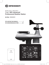
Bresser 7002534 Bedienungsanleitung

Kategorie
Wetterstationen
Typ
Bedienungsanleitung
GB
INSTRUCTION MANUAL
DE
BEDIENUNGSANLEITUNG
WI-FI Colour Weather Station
w. 4-in-1 UV/Light Sensor
W-LAN Farb-Wetterstation
m. 4-in-1 UV-/Licht-Sensor
Art. No. 7002534
2
DE
Besuchen Sie unsere Website über den folgenden QR Code oder Weblink um weitere
Informationen zu diesem Produkt oder die verfügbaren Übersetzungen dieser Anleitung zu
finden.
EN
Visit our website via the following QR Code or web link to find further information on this
product or the available translations of these instructions.
FR
Si vous souhaitez obtenir plus d’informations concernant ce produit ou rechercher ce mode
d’emploi en d’autres langues, rendez-vous sur notre site Internet en utilisant le code QR ou le
lien correspondant.
NL
Bezoek onze internetpagina via de volgende QR-code of weblink, voor meer informatie over dit
product of de beschikbare vertalingen van deze gebruiksaanwijzing.
IT
Desidera ricevere informazioni esaustive su questo prodotto in una lingua specifica? Venga
a visitare il nostro sito Web al seguente link (codice QR Code) per conoscere le versioni
disponibili.
ES
¿Desearía recibir unas instrucciones de uso completas sobre este producto en un idioma
determinado? Entonces visite nuestra página web utilizando el siguiente enlace (código QR)
para ver las versiones disponibles.
CA
Voleu una guia detallada d'aquest producte en un idioma específic? Visiteu el nostre lloc web
a través del següent enllaç (codi QR) per accedir a les versions disponibles.
PT
Deseja um manual detalhado deste produto numa determinada língua? Visite a nossa Website
através da seguinte ligação (QR Code) das versões disponíveis.
www.bresser.de/P7002534
www.bresser.de/warranty_terms
GARANTIE · WARRANTY · GARANTÍA · GARANZIA
3
GB
INSTRUCTION MANUAL ...................4
DE
BEDIENUNGSANLEITUNG ...............27
TABLE OF CONTENTS
INTRODUCTION . . . . . . . . . . . . . . . . . . . . . . . . . . . . . . . . . . . . . . . . . . . . 5
OVERVIEW . . . . . . . . . . . . . . . . . . . . . . . . . . . . . . . . . . . . . . . . . . . . . . . 5
INSTALLATION AND SETUP . . . . . . . . . . . . . . . . . . . . . . . . . . . . . . . . . . . . . 7
CREATE WEATHER SERVER ACCOUNT & SETUP WI-FI CONNECTION . . . . . . . . . . . 10
OTHER SETTING & FUNCTIONS OF THE CONSOLE . . . . . . . . . . . . . . . . . . . . . . 17
MAINTENANCE . . . . . . . . . . . . . . . . . . . . . . . . . . . . . . . . . . . . . . . . . . . 23
PRECAUTIONS . . . . . . . . . . . . . . . . . . . . . . . . . . . . . . . . . . . . . . . . . . . 24
SPECIFICATIONS . . . . . . . . . . . . . . . . . . . . . . . . . . . . . . . . . . . . . . . . . . 24
5
INTRODUCTION
Thank you for selecting this weather station with 4-in-1 professional sensor. This system gathers and
automatically uploads accurate and detailed weather data to Weather Underground and Weathercloud
website - the famous weather service which allows weather observers to upload their local weather data with
automated personal weather stations (PWS) - at which you can access and upload your weather data freely.
This product oers professional weather observers or serious weather enthusiasts robust performance with
a wide range of options and sensors. You will get your own local forecast, current and high/lows for virtually
all weather variables without using a PC.
This Weather Station which transmits outdoor temperature, Humidity, UV and light intensity data, which
can add to a sensor array of maximum 7 units, transmits your temperature & humidity to the console. Both
sensors are fully assembled and calibrated for your easy installation. They send data at a low power radio
frequency to the console from up to 150m/450 feet away (line of sight).
In the console, a high-speed processor is embedded to analyze the received weather data and these real-
time data can be published to Wunderground.com and weathercloud.net through your home Wi- router.
The console can also synchronize with internet time server to keep the time and weather data time stamp
of high precision. The color background LCD display shows informative weather readings with advanced
features, such as high/low alert alarm, dierent weather index, and MAX/MIN records. With calibration and
moon phase feature, this system is truly a remarkably personal yet professional weather station for your own
backyard.
NOTE:
This instruction manual contains useful information on the proper use and care of this product. Please read
this manual through to fully understand and enjoy its features, and keep it handy for future use.
OVERVIEW
CONSOLE
1
2
3
4
6
7
5
8
12
13
10
14
21
20
19
15
16
23
24
17
18
22
11
9
6
1. [ ALARM / SNOOZE ] key
2. LCD display
3. [ HISTORY ] key
4. [ UV ] key
5. [ LIGHT ] key
6. [ MAX / MIN ] key
7. [ INDEX ] key
8. [ BARO ] key
9. Table stand
10. Wall mounting holder
11. [ ALERT ] key
12. [ ALARM ] key
13. [ CLOCK SET ] key
14. [ HI / LO / AUTO ] key
15. [ REFRESH ] key
16. [ WI-FI ] key
17. Battery door
18. USB Power socket
19. [
] key
20. [
] key
21. [ RESET ] key
22. [ CHANNEL ] key
23. [ SENSOR ] key
24. [ °C / °F ] slide switch
LCD DISPLAY
1
2
3
4
5
6
Display section:
1. UV and sunburn time
2. Outdoor temperature & humidity
3. Time, calendar & moon phase
4. Weather forecast
5. Light intensity, baro and weather index
6. Indoor / Channel temperature & humidity
WIRELESS 4-IN-1 PROFESSIONAL SENSOR
1. UV & Light intensity sensor
2. Radiation shield
3. Battery compartment
4. Bottom case
5. Mounting clamps for bottom case
6. LED indicator
7. [ RESET ] key
3
6
4
5
2
7
1
7
INSTALLATION AND SETUP
INSTALL WIRELESS 4-IN-1 WEATHER SENSOR
Your Wireless 4-in-1 sensor measures UV, light intensity, temperature and humidity for you. It’s assembled
and calibrated for your easy installation.
1. Turn the top case anti-clockwise to open.
Step 1
2. Remove the battery door.
3. Insert 3x AA size batteries into the battery
compartment, then close the battery door.
NOTE
Make sure you insert the batteries in right way
according to the polarity information marked on
the battery compartment. Once installed, the LED
indicator ashes and start transmit the signals.
Step 2 Step 3
4. Twist the Top case clockwise.
Step 4
5. Insert the top side of the pole to the botton of the
Mounting clamps
6. Place the nut in the hexagon hole of the clamps,
then insert the screw in other side and then
tighten it by the screw driver.
NOTE:
Ensure the pole indicator align the clamps
screw hole.
Step 5
Step 6
7. Mount the clamps to the 4-in-1 sensor bottom
case with the big screws and nuts
Step 7
8
8. Insert the other side of the pole to the square
hole of the plastic stand
NOTE:
Ensure the pole and stand's indicator align.
Step 8
9. Place the nut in the hexagon hole of the stand,
then insert the screw in other side and then
tighten it by the screw driver.
Step 9
10. Add rubber pads before mount on the pole.
NOTE
Pole not included
Step 10
MOUNTING GUIDELINES
- Secure the clamps (included) to a post or pole.
- Install the sensor at least 1.5m o the ground for better and more accurate measurements.
- Choose an open area within 150 meters from the LCD display console.
NOTE:
- After replacing the batteries of the wireless sensor or the unit fails to receive wireless sensor signal of a
specied channel, you need to press and hold [ SENSOR ] key on the console to pair this sensor again.
- Avoid placing the transmitter in direct sunlight, rain or snow.
- The building material and the position of the receiver and transmitter aect the eective range. So try
various locations to obtain the best result.
- Place the units away from metal objects and electrical appliances to minimize the interference. Position
the receiver and transmitter within the eective transmission range: 150m in usual circumstances.
SETUP THE CONSOLE
INSTALL THE BACKUP BATTERY
1. Remove the battery door of the console.
2. Insert a new CR2032 battery as per the polarity information marked on the battery compartment.
3. Replace the battery door.
NOTE:
The backup battery can backup: Time & Date, Max/Min & Past 24 hours weather records, Alert setting
values, oset value of weather data and Sensor(s) channel history.
The built-in memory can backup: Router setting and Weather server setting
9
POWER UP THE CONSOLE
1. Plug the power adapter USB plug to power
up the main unit.
2. Once the main unit power up, all the
segments of the LCD will be shown.
3. The console will automatically start AP mode.
USB socket
NOTE:
If no display appears on the LCD after you plug the adaptor, press [ RESET ] key by using a pointed object.
TABLE STAND INSTALLATION
The unit is designed for desktop or wall mount for easy viewing. follow the steps below to hook the table
stand on the botton of the console.
Step 1 Step 2
SET LCD DISPLAY VIEWING ANGLE
Press [ ] or [ ] key in normal mode to adjust LCD viewing angle to t table stand or wall mount
situation.
PAIRING WIRELESS 4-IN-1 WEATHER SENSOR & CONSOLE
After insert of batteries, the console will automatically search and connect the Wireless 4-in-1 sensor (the
sensor antenna icon blinking).
Once the connection is successful, antenna icon and readings for outdoor temperature & humidity, UV and
Baro pressure will appear on the LCD.
CHANGING BATTERIES AND MANUAL PAIRING OF SENSOR
Whenever you changed the batteries of the Wireless 4-in-1 sensor, pairing must be done manually.
1. Change all the batteries to new ones in the sensor.
2. Press [ SENSOR ] key on the console.
3. Press [ RESET ] key on the Wireless 4-in-1 sensor.
PAIRING ADDITIONAL WIRELESS SENSOR(S) & CONSOLE (OPTIONAL)
This console can support up to 7 additional wireless sensor(s). You can press [SENSOR ] key to search
the on display channel's sensor manually. Once your sensor paired up, the sensor signal strength indicator
and weather reading will appear on your console display.
NOTE:
- The additional wireless sensor(s) is not included.
- This console can support dierent type of additional wireless sensor, e.g. soil moisture and pool sensor.
Check with your retailer for more detail.
10
CREATE WEATHER SERVER ACCOUNT & SETUP WI-FI CONNECTION
The console can upload weather data to WUnderground and / or Weathercloud through WI-FI router. you
can follow the step below to setup your device.
NOTE:
The Weather Underground and Weathercloud website are subject to change.
CREATE WEATHER UNDERGROUND ACCOUNT
1. In https://www.wunderground.com click the "Join" on the top right corner to open the registration page.
Follow the instructions to create your account.
NOTE:
Use the valid email address to register your account.
2. After you have created your account and completed the Email validation, please go back to the
WUndergound web page to login. Then, click “My Prole” button on the top to open the drop-down
menu and click "My Weather Station".
3. In "My Weather Station" page bottom, please the "Add New Device" button to add your device.
4. Follow their instruction to enter your station information, in the Step "Tell Us More About Your Device",
enter a Name for your weather station, then choose “Other” in “Device Hardware” section. ll in other
the other information and select "I Accept" to accept Weather underground's privacy terms, then click
Next” to create your station ID and key.
11
5. Jot down Your "Station ID" and "Station key" for the further setup step.
12
CREATE WEATHERCLOUD ACCOUNT
1. In https://weathercloud.net enter your information in "Join us today" section, then follow the
instructions to create your account.
NOTE:
Use the valid email address to register your account.
2. Sign in weathercloud and then you will go the "Devices" page, click "+ New" to create new device.
3. Enter all the information in Create new device page, for the Model* selection box select the "W100
Series" under "CCL" section. for the Link type* selection box select the "Pro Weather Link", Once you
have completed, click Create.
13
4. Jot down your ID and key for the further setup step.
SETUP WI-FI CONNECTION
1. When you rst power up the console, or press and hold the [ WI-FI ] key for 6 seconds in normal mode,
the console LCD will show "AP" and " " icon to signify that it has entered AP (access point) mode,
and is ready for WI-FI settings.
2. Use the smart phone, tablet, or computer to connect to the console through WI-FI.
3. In PC choose WiFi network settings or In Android / iOS choose setting WI-FI to select the console’s
SSID: PWS-XXXXXX in the list and it will need several second to connect.
PWS-XXXXXX
PWS-XXXXXX
PC WI-FI network interface Android WI-FI network interface
4. Once connected, enter the following IP address into your internet browser’s address bar, to access the
console’s web interface:
http://192.168.1.1
NOTE :
- Some browsers will treat 192.168.1.1 as a search, so make sure you include http:// header.
- Recommended browsers, such as the latest version of Chrome, Safari, Edge, Firefox or Opera.
14
SETUP THE WEATHER SERVER CONNECTION
Enter the following information into the below web interface "SETUP" page. If you choose not to use
Wunderground.com or Weathercloud.net, leave the check boxes unchecked.
Press to enter setup
settings page
Press to search for router
Cryptic password record (if
password is entered)
Current Station ID & Key
(if existing)
Current Station ID & Key
(if existing)
Select router you want to connect to
Enter SSID manually if not listed
Select router's security type (usually WAP2)
Enter router's password (leave blankif it is not password
protected)
Check to conrm upload to Wunderground
Enter new Station ID & Key
provided by Wunderground
Check to conrm upload to Weathercloud
Enter new Station ID & Key
provided by Weathercloud
Select time server
Press to complete the setup settings
Function firmware version: 1.00
WiFi firmware version: 1.00
nist.time.gov
Server URL:
Time server setup
WiFi Router setup
SETUP ADVANCED
Wunderground
Station ID:
WDw124
******
******
******
IPACIR23Wc
Weather server setup
Station key:
Router:
Add Router
Search
Security type:
Router Password:
WAP2
ROUTER_A
Apply
Language: English
Weathercloud
Station ID:
Station key:
Mac address 00:0E:C6:00:07:10
Setup settings
NOTE:
- When WI-FI setup is complete, your PC or mobile will resume your default WI-FI connection.
- During AP mode, you can press and hold the [ WI-FI ] key for 6 seconds to stop AP mode and the
console will restore your previous setting.
WI-FI CONNECTION STATUS
Below is the WI-FI icon status on the console LCD:
Stable: Console is in
connection with WI-FI router
Flashing: Console is trying to
connect to WI-FI router
Flashing: Console currently in
Access Point (AP) mode
TIME SERVER CONNECTION STATUS
After the console has connected to the internet, it will attempt to connect to the internet time server to
obtain the UTC time. Once the connection succeeds and the console's time has been updated, the “
icon will appear on the LCD.
Time zone: To display the time of your time-zone, change the time zone in CLOCK setting mode from '00'
(default) to your time zone (e.g.08 for Hong Kong).
1. Press and hold [ CLOCK SET ] key for 2s to enter time setting mode.
2. Press [
] or [ ] key to enter your time zone, then press and hold [ CLOCK SET ] key to conrm and
exit. Please refer to CLOCK SETTING session of manual for details of other setting for the console.
The time will automatically synchronize Internet time server at 12:00AM and 12:00PM per day. Also you
can press the [ REFRESH ] key to get the internet time manually within 1 minute.
15
ADVANCE SETTING IN WEB INTERFACE
Press "ADVANCED" key at the top of web interface to enter the advance setting page, this
page allow you to set and view the calibration data of the console, also you can update the
rmware in here (Only available in PC platform).
-560~ 560hpa / -16.54 ~ 16.54inHg / -420 ~ 420mmHg
Setting Range:
SETUP ADVANCED
Language: English
Temperature
o
C
Outdoor
Indoor
CH 1
CH 2
CH 3
CH 4
CH 5
CH 6
CH 7
Humidity %
Relative Pressure Offset:
Absolute Pressure Offset:
hpa
Range: -20 ~ 20
(Default: 0.0)
Current offset: 10Current offset: -9
Current offset: -5Current offset: 2
Current offset: -2Current offset: 3
Current offset: -2Current offset: 1.2
Current offset: -5Current offset: -0.2
Current offset: -3Current offset: -20.1
Current offset: -10Current offset: 11.5
Current offset: -3
Current offset: -3
(Default: 0)
Current offset: 10
(Default: 0)
Current offset: 0.2
Current offset: -5Current offset: 1
Pressure
Range: -20.0 ~ 20.0
o
C
-36.0 ~ 36.0
o
F (Default: 0.0)
**UV gain:
Range: 0.01 ~ 10(Default: 1.00)
Current gain: 1.1
**Light gain:
Range: 0.01 ~ 10(Default: 1.00)
Current gain: 1.0
** Depend on the model
**Wind speed gain:
**Wind direction:
**Rain gain:
Range: 0.5 ~ 1.5(Default: 1.00)
Range: -10 ~ 10(Default: 0
o
)
Range: 0.5 ~ 1.5(Default: 1.00)
Current gain: 0.85
Current offset: 2
o
Current gain: 0.75
Function firmware version: 1.00
WiFi firmware version: 1.00
Select unit
Temperature calibration
Pressure calibration
Wind calibration
Press to enter advanced
settings page
Humidity calibration
Select unit
Advanced settings
CALIBRATION
1. User may enter or change the oset and gain values for dierent measurement parameters while current
oset and gain values are shown next to their corresponding boxes.
2. Once completed, press
Apply
in the SETUP page
The current oset value will show the previous value that you entered, if you want to change, just input the
new value in the blank, the new value will valid once you press
Apply
icon in SETUP page.
NOTE:
Calibration of most parameter is not required, with the exception of Relative Pressure, which must be
calibrated to sea-level to account for altitude eects.
VIEW YOUR WEATHER DATA IN WUNDERGROUND
To view your weather station's temperature, humidity, baro UV and light intensity live data in a web browser
(PC or mobile version), please visit http://www.wunderground.com, and then enter your “Station ID” in the
searching box. Your weather data will show up on the next page. You can also login your account to view
and download the recorded data of your weather station.
16
Another way to view your station is use the web browser URL bar, type below in the URL bar:
https://www.wunderground.com/dashboard/pws/XXXX
Then replace the XXXX by your Weather underground station ID to go to your station live view directly.
You can also use the Apple ipad's "WunderStation" app to login your own weather station to view the live
data.
WunderStation
VIEWING YOUR WEATHER DATA IN WEATHERCLOUD
1. To view your weather station temperature, humidity, baro UV and light intensity live data in a web
browser (PC or mobile version), please visit https://weathercloud.net and sign in your own account.
2. Click the
icon inside the pull down menu of your station.
3. Click "Current", "Evolution" or "Inside" icon to view the live data of your weather station.
FIRMWARE UPDATE
The console supports OTA rmware update capability. Its rmware may be updated over the air anytime
(whenever necessary) through any web-browser on a PC with WI-FI connectivity. Update function,
however, is not available through mobile/smart devices.
Two types of rmware updates are available, namely Function Firmware and System WI-FI Firmware, and
are located at the bottom of ADVANCED page.
17
Current Function
firmware version
Current WI-FI
firmware version
FIRMWARE UPDATE STEP
1. Download the latest version rmware (function or WI-FI) to your PC.
2. Set the Console into AP (access point) mode then connect the PC to the console (ref to "SETUP WI-FI
CONNECTION" section in previous page).
3. To update the Function rmware, click the
Browse
in Function rmware section and browse to the
location of the le you download in step 1. To update the WI-FI rmware, click the
Browse
in WI-FI
rmware section.
4. Click the corresponding
Upload
to start transfer
the rmware le to console (indicated by a transfer
completion %).
Upload
30% ...
BrowseC:\download\PWS_SYS.bin
Upload
Browse
Function firmware version: 1.00
WiFi firmware version: 1.00
3
4
5. Once the console received the rmware le, it
executes the update automatically as indicated by the
update progress on left top side of the display (i.e.
100 is completion).
e.g. 50% update progress
6. The console will restart once the update completed.
NOTE:
- Function and WI-FI rmware cannot be updated at the same time, you need to update one by one.
- Please keep connecting the power during the rmware update process.
- Please make sure your PC's WI-FI connection is stable.
- When the update process start, do not operate the PC and console.
- During rmware update, the console will temporary stop upload data. It will reconnect to your WI-FI router
and upload the data again once the update success. If the console cannot reconnect to your router and/or
upload the weather data, please enter the SETUP page to setup again.
OTHER SETTING & FUNCTIONS OF THE CONSOLE
CLOCK SETTING
This console is designed to obtain the local time by synchronize with the assigned internet time server. If you
want to use it oine, you can set the time and date manually. During the rst time startup, press and hold the
[ WI-FI ] key for 6 seconds and let the console back to normal mode.
18
1. In normal mode, press and hold [ CLOCK SET ] key for 2 seconds to enter setting.
2. The setting sequence: Time Zone DST ON/OFF Hour Minute 12/24 hour format Year
Month Day M-D / D-M format Select N/S hemisphere moon phase Time sync ON/OFF
weekday Language.
3. Press [
] or [ ] key to change the value. Press and hold the key for quick-adjust.
4. Press [ CLOCK SET ] key to save and exit the setting mode, or the unit will automatically exit the setting
mode 60 seconds later without pressing any key.
NOTE:
- In normal mode, press [ CLOCK SET ] key to switch between year and date display.
- During the setting, you can press and hold [ CLOCK SET ] key for 2 seconds to back to normal model.
MOON PHASE
The moon phase is determined by the
time, date and time zone. The following
table explains the moon phase icons of the
Northern and Southern hemispheres. Select
the Northern and Southern hemispheres by
using the " Select N/S hemisphere moon
phase" in [ CLOCK SET ]
Northern
hemisphere
Moon Phase
Southern
hemisphere
New Moon
Waxing Crescent
First quarter
Waxing Gibbous
Full Moon
Waning Gibbous
Third quarter
Waning Crescent
SETTING ALARM TIME
1. In normal time mode, press and hold [ ALARM ] key for 2 seconds until the alarm hour digit ashes to
enter alarm time setting mode.
2. Press [
] or [ ] key to change the value. Press and hold the key for quick-adjust.
3. Press [ ALARM ] key again to step the setting value to Minute with the Minute digit ashing.
4. Press [
] or [ ] key to adjust the value of the ashing digit.
5. Press [ ALARM ] key to save and exit the setting.
NOTE:
- In alarm mode, the “
” icon will display on the LCD.
- The alarm function will turn on automatically once you set the alarm time.
ACTIVATING ALARM AND TEMPERATURE PRE-ALARM FUNCTION
1. In normal mode, press [ ALARM ] key to show the alarm time for 5 seconds.
2. When the alarm time displays, press [ ALARM ] key again to activate the alarm function. Or press
[ALARM ] key twice to activate the alarm with ice pre-alarm function.
Alarm o Alarm on Alarm with ice-alert
NOTE:
Once the ice pre-alert activates, the pre-set alarm will sound and ice-alert icon will ash 30 minutes earlier if
the outdoor temperature is below -3°C.
19
When clock reach the alarm time, alarm sound will start.
Where it can be stopped by following operation:
- Auto-stop after 2 minutes alarming if without any operation and the alarm will activate again in the next
day.
- By pressing [ ALARM / SNOOZE ] key to enter snooze that the alarm will sound again after 5 minutes.
- By pressing and hold [ ALARM / SNOOZE ] key for 2 seconds to stop the alarm and will activate again
in the next day.
- By pressing [ ALARM ] key to stop the alarm and the alarm will activate again in the next day.
NOTE:
- The snooze could be used continuously in 24 hours.
- During the snooze, the alarm icon “
” will keep ashing.
TEMPERATURE / HUMIDITY FUNCTION & TREND
Use the [ °C / °F ] slide switch to select the temperature display unit.
The temperature / humidity trend indicator shows the trends of changes in the forthcoming few minutes.
Arrow indicator
Temperature / Humidity trend
Rising Steady Falling
NOTE:
- When indoor temperature is below -40°C, the LCD will display “Lo”. If temperature is above 70°C, LCD
will display “HI”.
- When outdoor temperature is below -40°C, the LCD will display “Lo”. If temperature is above 80°C, LCD
will display “HI”.
- When humidity is below 1%, LCD will display “Lo”. If humidity is above 99%, LCD will display “HI”.
COMFORT INDICATION
The comfort indication is a pictorial indication based on indoor or channel's air temperature and
humidity in an attempt to determine comfort level.
Too cold Comfortable Too hot
NOTE:
- Comfort indication can vary under the same temperature, depending on the humidity.
- There is no comfort indication when temperature is below 0°C (32°F) or over 60°C (140°F).
WIRELESS SENSOR SIGNAL RECEIVING
1. The console display signal strength for the Wireless 4-in-1 sensor, as per table below:
No signal Weak signal Good signal
2. If the signal has discontinued and does not recover within 15 minutes, the signal icon will disappear.
The temperature and humidity will display “Er” for the corresponding channel.
3. If the signal does not recover within 48 hours, the “Er” display will become permanent. You need to
replace the batteries and then press [ SENSOR ] key to pair up the sensor again.
VIEW THE OUTDOOR CHANNEL (OPTIONAL FEATURE WITH ADD ON EXTRA THERMAL
HYGRO SENSORS)
This console is capable to pair with a Wireless 4-in-1 sensor and up to 7 wireless thermal-hygro sensors,
pool sensor or soil sensor. If you have 2 or more sensors, you can press [ CHANNEL ] key to switch
between dierent wireless channels in normal mode, or press and hold [ CHANNEL ] key for 2 seconds to
toggle auto-cycle mode to display the connected channels at 4 seconds interval.
During auto-cycle mode, press [ CHANNEL ] key to stop auto cycle and display the current channel.
20
UV & SUNBURN TIME
UV & SECTION OVERVIEW
This section can show the UV index and sunburn time, press the [ UV ] key to change the mode.
UV INDEX MODE:
This mode is showing the currect UV index that detect
by the wireless weather sensor. The corresponding
exposure level and suggested protection indicator are
also showing.
Exposure
Level
Recommended
protection indicator
UV index
SUNBURN TIME MODE:
This mode is showing the recommend sunburn time
that according to current UV level.
Sunburn
time
UV INDEX & SUNBURN TIME TABLE
Display
Exposure
level
Low Moderate High
UV index 1 2 3 4 5 6
Sunburn time N/A 45 minutes 30 minutes
Recommended
protection
indicator
N/A
Moderate or high UV level! Suggest to
wear sunglasses, broad brim hat and
long-sleeved clothing.
Display
Exposure level High Very high Extreme
UV index 7 8 9 10 11 12 ~ 16
Sunburn time 30 minutes 15 minutes 10 minutes
Recommended
protection
indicator
Very high or Extreme UV level! Suggest to wear
sunglasses, broad brim hat and long-sleeved clothing,
If you have to stay outdoors, make sure to seek shade.
1 / 1

Bresser 7002534 Bedienungsanleitung

Kategorie
Wetterstationen
Typ
Bedienungsanleitung

in anderen Sprachen