Norwell NW503 Sign Installationsanleitung
- Typ
- Installationsanleitung

SURFACE MOUNT
·
OBERFLÄCHE
INSTALLATION MANUAL • MONTAGEANLEITUNG

INSTALLATION MANUAL · SURFACE MOUNT · OBERFLÄCHE
www.norwell.dk · [email protected] COPYRIGHT © 2017 Norwell A/S
2
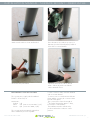
Make sure the surface is clean and leveled. Place the stations according to positions on
drawings (see the following pages). Drill bolt
holes with a concrete hammer.
Mount the M12/M16 bolts. Tighten the bolts (M12 = 90 N/m and
M16 = 120 N/m), and cover with the
surface material chosen.
REQUIREMENTS FOR THE CONCRETE
The concrete must comply with the standard
EN197-1 CEM I 52,5 N.
Mixing ratio:
Cement 1/8
Sand 3/8 (max. stone size 4mm / 0,2”)
Stones 4/8 (stone size 16mm / 0,6”)
The concrete must be premixed or mixed in a
mixer. Hand mixing is not acceptable.
For the concrete to settle, it must be vibrated
with a concrete vibrator.
To ensure correct contact between the base
plate and the concrete, the concrete surface
must be 100% plane.
The concrete has to have the strength of
≥
52,5 MPa (obtained in approx. 7 days,
but longer in cold weather).
The installation must be carried out by
professionals and according to current
practice.

INSTALLATION MANUAL · SURFACE MOUNT · OBERFLÄCHE
www.norwell.dk · [email protected] COPYRIGHT © 2017 Norwell A/S
3
Stellen Sie sicher, dass die Oberfläche sauber
und eben ist.
Platzieren Sie die Stationen entsprechend der
Positionen auf den Bildern (sie nächste Seiten).
Bohren Sie Löcher mit einem Bohrhammer.
Befestigen Sie die Schwerlastdübel
M12/M16.
Spannen Sie die Schwerlastdübel mit einem
Drehmoment bei M12 = 90 N/m und
M16 = 120 N/m an und bedecken Sie sie
mit dem gewünschten Oberflächenmaterial.
BETONVORGABEN
Der Beton muss den Standards EN197-1 CEM I 52,5 N
entsprechen.
Mischangaben:
Zement 1/8
Sand 3/8 (max. Steingröße 4mm / 0,2”)
Steine 4/8 (Steingröße 16mm / 0,6”)
Der Beton muss entweder Fertigbeton sein oder in einem
Betonmischer gemischt werden. Mischen von Hand ist
nicht akzeptabel.
Damit der Beton sich setzten kann, muss er mit einem
Betonrütteler verdichtet werden.
Um einwandfreien Kontakt zwischen der Basisplatte
und dem Beton zu gewährleisten, muss der Betonboden
100% eben sein.
Der Beton muss mindestens eine Druckfestigkeit
von ≥52,5 MPa haben (wird nach ca. 7 Tagen
erreicht, länger bei kaltem Wetter).
Die Installation muss von ausgebildeten Fachpersonal
nach neusten Methoden ausgeführt werden.

INSTALLATION MANUAL · SURFACE MOUNT · OBERFLÄCHE
www.norwell.dk · info@norwell.dk COPYRIGHT © 2017 Norwell A/S
4
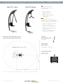
NW101 Chest NW102 Back
POSITION AND TRAINING ZONE:
POSITION UND TRAININGSZONE:
CONCRETE DEPTH:
BETON TIEFE:
0,50m
0,70m
BETONBLOK
See separate page with the
preparatory work for surface
mount installation.
• Install onto surface.
• Assemble and line up.
• Place on surface.
• Mark position of bolt holes.
• Fasten each base plate with
4 x M16 bolts.
PART LIST:
BESTANDTEIL LISTE:
4 x M16
BASE PLATE:
BASISPLATTE:
40 x 40cm / 16” x 16”
Auf der separaten Seite finden Sie
Angaben zu vorbereitenden Maßnahmen
für eine Installation an der Oberfläche.
• Wird an der Oberfläche installiert.
• Bauen Sie zunächst die Teile
zusammen und stellen Sie sie auf.
• Platzieren Sie sie auf dem Beton.
• Markieren Sie die Positionen der
Schraubenlöcher.
• Fixieren Sie jede Basisplatte mit
4 x M16 Schwerlastdübeln.
CONCRETE
BLOCK /
BETONBLOCK
0,50m/ 20”
0,70m/ 27,5”
12 m
2
/ 129 ft
2
Training zone =
2,20m / 86,5”
3,90m / 153,5”
3,70m / 145,5”
1,85m / 73”
0,7m / 27,5”
0,7m / 27,5”

INSTALLATION MANUAL · SURFACE MOUNT · OBERFLÄCHE
www.norwell.dk · info@norwell.dk COPYRIGHT © 2017 Norwell A/S
5
NW103 Sit Up
See separate page with the
preparatory work for surface
mount installation.
• Install onto surface.
• Assemble and line up.
• Place on concrete.
• Mark position of bolt holes.
• Fasten each base plate with
4 x M12 bolts.
POSITION AND TRAINING ZONE:
POSITION UND TRAININGSZONE:
CONCRETE DEPTH:
BETON TIEFE:
0,50m
0,50m
CONCRETE
BLOCK /
BETONBLOCK
0,50m/ 20”
0,50m/ 20”
PART LIST:
BESTANDTEIL LISTE:
8 x M12
BASE PLATE:
BASISPLATTE:
25 x 25cm / 10” x 10”
Auf der separaten Seite finden Sie
Angaben zu vorbereitenden Maßnahmen
für eine Installation an der Oberfläche.
• Wird an der Oberfläche installiert.
• Bauen Sie zunächst die Teile
zusammen und stellen Sie sie auf.
• Platzieren Sie sie auf dem Beton.
• Markieren Sie die Positionen der
Schraubenlöcher.
• Fixieren Sie jede Basisplatte mit
4 x M12 Schwerlastdübeln.
15m
2
/ 161,5 ft
2
Training zone =
0,5m /20”
0,5m /20”
1,5m /59” 2,05m /80,7”
5,05m /199”
1,70m /67”
3,40m /134”

INSTALLATION MANUAL · SURFACE MOUNT · OBERFLÄCHE
www.norwell.dk · info@norwell.dk COPYRIGHT © 2017 Norwell A/S
6
NW104 Pull Up
See separate page with the
preparatory work for surface mount
installation.
• Install onto surface.
• Assemble and line up.
• Place on concrete.
• Mark position of bolt holes.
• Fasten each base plate with
4 x M16 bolts.
POSITION AND TRAINING ZONE:
POSITION UND TRAININGSZONE:
2,35m / 92,5”
1,00m
0,50m
CONCRETE BLOCK /
BETONBLOCK
0,50m/ 20”
1,00m/ 39”
CONCRETE DEPTH:
BETON TIEFE:
PART LIST:
BESTANDTEIL LISTE:
8 x M16
BASE PLATE:
BASISPLATTE:
40 x 40cm / 16” x 16”
Auf der separaten Seite finden Sie
Angaben zu vorbereitenden Maßnahmen
für eine Installation an der Oberfläche.
• Wird an der Oberfläche installiert.
• Bauen Sie zunächst die Teile
zusammen und stellen Sie sie auf.
• Platzieren Sie sie auf dem Beton.
• Markieren Sie die Positionen der
Schraubenlöcher.
• Fixieren Sie jede Basisplatte mit
4 x M16 Schwerlastdübeln.
23m
2
/ 247,5 ft
2
Training zone =
1,0m /39”
0,7m /27,5”
3,20m /126”
5,35m /210,5”
2,10m /82,5”0,98m /38,5”
5,20m /205”

INSTALLATION MANUAL · SURFACE MOUNT · OBERFLÄCHE
www.norwell.dk · info@norwell.dk COPYRIGHT © 2017 Norwell A/S
7
NW105 Bar
See separate page with the
preparatory work for surface mount
installation.
• Install onto surface.
• Assemble and line up.
• Place on concrete.
• Mark position of bolt holes.
• Fasten each base plate with
4 x M12 bolts.
POSITION AND TRAINING ZONE:
POSITION UND TRAININGSZONE:
0,50m
0,50m
Auf der separaten Seite finden Sie
Angaben zu vorbereitenden Maßnahmen
für eine Installation an der Oberfläche.
• Wird an der Oberfläche installiert.
• Bauen Sie zunächst die Teile
zusammen und stellen Sie sie auf.
• Platzieren Sie sie auf dem Beton.
• Markieren Sie die Positionen der
Schraubenlöcher.
• Fixieren Sie jede Basisplatte mit
4 x M12 Schwerlastdübeln.
CONCRETE DEPTH:
BETON TIEFE:
PART LIST:
BESTANDTEIL LISTE:
8 x M12
BASE PLATE:
BASISPLATTE:
25 x 25cm / 10” x 10”
CONCRETE
BLOCK /
BETONBLOCK
0,50m/ 20”
0,50m/ 20”
12,5m
2
/ 134,5 ft
2
Training zone =
0,5m /20”
0,5m /20”
0,5m /20”
3,50m /138”
1,50m /59”
1,50m /59”
4,00m /157,5”

INSTALLATION MANUAL · SURFACE MOUNT · OBERFLÄCHE
www.norwell.dk · info@norwell.dk COPYRIGHT © 2017 Norwell A/S
8
NW106 Leg
POSITION AND TRAINING ZONE:
POSITION UND TRAININGSZONE:
0,50m
0,70m
See separate page with the
preparatory work for surface mount
installation.
• Install onto surface.
• Assemble and line up.
• Place on concrete.
• Mark position of bolt holes.
• Fasten each base plate with
4 x M16 bolts.
CONCRETE DEPTH:
BETON TIEFE:
PART LIST:
BESTANDTEIL LISTE:
4 x M16
BASE PLATE:
BASISPLATTE:
40 x 40cm / 16” x 16”
Auf der separaten Seite finden Sie
Angaben zu vorbereitenden Maßnahmen
für eine Installation an der Oberfläche.
• Wird an der Oberfläche installiert.
• Bauen Sie zunächst die Teile
zusammen und stellen Sie sie auf.
• Platzieren Sie sie auf dem Beton.
• Markieren Sie die Positionen der
Schraubenlöcher.
• Fixieren Sie jede Basisplatte mit
4 x M16 Schwerlastdübeln.
CONCRETE
BLOCK /
BETONBLOCK
0,50m/ 20”
0,70m/ 27,5”
1,0m /39”
0,7m / 27,5”
3,40m /134”
1,7m /67”
12 m
2
/ 129 ft
2
Training zone =
2,07m / 81,5”
3,60m /142”

INSTALLATION MANUAL · SURFACE MOUNT · OBERFLÄCHE
www.norwell.dk · info@norwell.dk COPYRIGHT © 2017 Norwell A/S
9
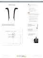
NW107 Dual Pull Up
2,20m / 86,5”
1,93m / 76”
See separate page with the
preparatory work for surface mount
installation.
• Install onto surface.
• Assemble and line up.
• Place on concrete.
• Mark position of bolt holes.
• Fasten each base plate with
4 x M16 bolts.
POSITION AND TRAINING ZONE:
POSITION UND TRAININGSZONE:
1,00m
0,50m
CONCRETE BLOCK /
BETONBLOCK
0,50m/ 20”
1,00m/ 39”
CONCRETE DEPTH:
BETON TIEFE:
PART LIST:
BESTANDTEIL LISTE:
8 x M16
BASE PLATE:
BASISPLATTE:
40 x 40cm / 16” x 16”
Auf der separaten Seite finden Sie
Angaben zu vorbereitenden Maßnahmen
für eine Installation an der Oberfläche.
• Wird an der Oberfläche installiert.
• Bauen Sie zunächst die Teile
zusammen und stellen Sie sie auf.
• Platzieren Sie sie auf dem Beton.
• Markieren Sie die Positionen der
Schraubenlöcher.
• Fixieren Sie jede Basisplatte mit
4 x M16 Schwerlastdübeln.
23m
2
/ 247,5 ft
2
Training zone =
1,3m /51”
0,7m /27,5”
3,0m /118”
5,35m /210,5”
0,98m /38,5”
2,10m /82,5”
5,20m /205”

INSTALLATION MANUAL · SURFACE MOUNT · OBERFLÄCHE
www.norwell.dk · info@norwell.dk COPYRIGHT © 2017 Norwell A/S
10
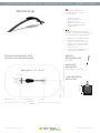
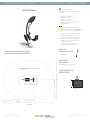
NW201 Air Walker
See separate page with the
preparatory work for surface mount
installation.
• Install onto surface.
• Assemble and line up.
• Place on concrete.
• Mark position of bolt holes.
• Fasten each base plate with
4 x M12 bolts.
POSITION AND TRAINING ZONE:
POSITION UND TRAININGSZONE:
PART LIST:
16 x M12
1 x cross bar
2 x sets of Nut caps, round
2 x M10x110 bolts
2 x Stainless Steel connector
Auf der separaten Seite finden Sie
Angaben zu vorbereitenden Maßnahmen
für eine Installation an der Oberfläche.
• Wird an der Oberfläche installiert.
• Bauen Sie zunächst die Teile
zusammen und stellen Sie sie auf.
• Platzieren Sie sie auf dem Beton.
• Markieren Sie die Positionen der
Schraubenlöcher.
• Fixieren Sie jede Basisplatte mit
4 x M12 Schwerlastdübeln.
CONCRETE DEPTH:
BETON TIEFE:
BASE PLATE:
BASISPLATTE:
25 x 25cm / 10” x 10”
1 x Handgriff
2 x Set Hutmuttern, rund
2 x M10x110 Bolzen
2 x Verbindungselement aus
rostfreiem Stahl
BESTANDTEIL LISTE:
16 x M12
0,50m
0,50m
CONCRETE
BLOCK /
BETONBLOCK
0,50m/ 20”
0,50m/ 20”
ASSEMBLING:
ZUSAMMENBAUEN:
Always secure bolts
with Loctite.
Sicheren Sie die
Bolzen immer durch das
Benetzten mit Loctite.
16,5m
2
/ 177,5 ft
2
Training zone =
0,5m /20”
0,5m /20”
0,85m /33,5”
1,50m /59”
1,50m /59”
5,50m /216,5”
2,44m /96,1”
3,85m /151,5”

INSTALLATION MANUAL · SURFACE MOUNT · OBERFLÄCHE
www.norwell.dk · info@norwell.dk COPYRIGHT © 2017 Norwell A/S
11
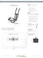
NW202 Cross
POSITION AND TRAINING ZONE:
POSITION UND TRAININGSZONE:
0,50m
0,70m
See separate page with the
preparatory work for surface mount
installation.
• Install onto surface.
• Assemble and line up.
• Place on concrete.
• Mark position of bolt holes.
• Fasten each base plate with
4 x M16 bolts.
CONCRETE DEPTH:
BETON TIEFE:
PART LIST:
BESTANDTEIL LISTE:
4 x M16
BASE PLATE:
BASISPLATTE:
40 x 40cm / 16” x 16”
Auf der separaten Seite finden Sie
Angaben zu vorbereitenden Maßnahmen
für eine Installation an der Oberfläche.
• Wird an der Oberfläche installiert.
• Bauen Sie zunächst die Teile
zusammen und stellen Sie sie auf.
• Platzieren Sie sie auf dem Beton.
• Markieren Sie die Positionen der
Schraubenlöcher.
• Fixieren Sie jede Basisplatte mit
4 x M16 Schwerlastdübeln.
CONCRETE
BLOCK /
BETONBLOCK
0,50m/ 20”
0,70m/ 27,5”
14m
2
/ 150,5 ft
2
Training zone =
5,25m /207”
2,62m /103”
1,80m / 71”
0,7m / 27,5”
3,60m /142”
0,7m / 27,5”

INSTALLATION MANUAL · SURFACE MOUNT · OBERFLÄCHE
www.norwell.dk · info@norwell.dk COPYRIGHT © 2017 Norwell A/S
12
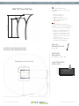
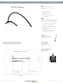
NW203 Stepper
POSITION AND TRAINING ZONE:
POSITION UND TRAININGSZONE:
See separate page with the
preparatory work for surface mount
installation.
• Install onto surface.
• Assemble and line up.
• Place on concrete.
• Mark position of bolt holes.
• Fasten each base plate with
4 x M12 bolts.
0,50m
0,50m
Auf der separaten Seite finden Sie
Angaben zu vorbereitenden Maßnahmen
für eine Installation an der Oberfläche.
• Wird an der Oberfläche installiert.
• Bauen Sie zunächst die Teile
zusammen und stellen Sie sie auf.
• Platzieren Sie sie auf dem Beton.
• Markieren Sie die Positionen der
Schraubenlöcher.
• Fixieren Sie jede Basisplatte mit
4 x M12 Schwerlastdübeln.
CONCRETE DEPTH:
BETON TIEFE:
PART LIST:
BESTANDTEIL LISTE:
16 x M12
BASE PLATE:
BASISPLATTE:
25 x 25cm / 10” x 10”
CONCRETE
BLOCK /
BETONBLOCK
0,50m/ 20”
0,50m/ 20”
15m
2
/ 161,5 ft
2
Training zone =
5,45m / 214,6”
2,45m / 96,5”
1,95m / 77” 1,50m /59”
0,5m /20”
0,45m /17,7”
3,45m /136”
0,9m /35,4”

INSTALLATION MANUAL · SURFACE MOUNT · OBERFLÄCHE
www.norwell.dk · info@norwell.dk COPYRIGHT © 2017 Norwell A/S
13
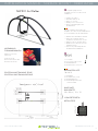
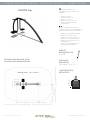
NW204 Hip
POSITION AND TRAINING ZONE:
POSITION UND TRAININGSZONE:
See separate page with the
preparatory work for surface mount
installation.
• Install onto surface.
• Assemble and line up.
• Place on concrete.
• Mark position of bolt holes.
• Fasten each base plate with
4 x M12 bolts.
0,50m
0,50m
Auf der separaten Seite finden Sie
Angaben zu vorbereitenden Maßnahmen
für eine Installation an der Oberfläche.
• Wird an der Oberfläche installiert.
• Bauen Sie zunächst die Teile
zusammen und stellen Sie sie auf.
• Platzieren Sie sie auf dem Beton.
• Markieren Sie die Positionen der
Schraubenlöcher.
• Fixieren Sie jede Basisplatte mit
4 x M12 Schwerlastdübeln.
CONCRETE DEPTH:
BETON TIEFE:
PART LIST:
BESTANDTEIL LISTE:
8 x M12
BASE PLATE:
BASISPLATTE:
25 x 25cm / 10” x 10”
CONCRETE
BLOCK /
BETONBLOCK
0,50m/ 20”
0,50m/ 20”
19m
2
/ 204,5 ft
2
Training zone =
5,45m / 214,6”
2,45m / 96,5” 1,50m / 59”
1,95m / 76,8”
3,90m / 153,5”
0,5m / 20”
0,5m / 20”

INSTALLATION MANUAL · SURFACE MOUNT · OBERFLÄCHE
www.norwell.dk · info@norwell.dk COPYRIGHT © 2017 Norwell A/S
14
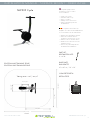
NW205 Cycle
POSITION AND TRAINING ZONE:
POSITION UND TRAININGSZONE:
14m
2
/ 150,5 ft
2
Training zone =
0,7m /27,5”
0,7m /27,5”
2,2m /87”
4,0m /157,5”
3,60m /142”
1,8m /71”
CONCRETE DEPTH:
BETON TIEFE:
BETONBLOK
See separate page with the
preparatory work for surface
mount installation.
• Install onto surface.
• Assemble and line up.
• Place on surface.
• Mark position of bolt holes.
• Fasten each base plate with
4 x M16 bolts.
PART LIST:
BESTANDTEIL LISTE:
4 x M16
BASE PLATE:
BASISPLATTE:
40 x 40 cm / 16” x 16”
Auf der separaten Seite finden Sie
Angaben zu vorbereitenden Maßnahmen
für eine Installation an der Oberfläche.
• Wird an der Oberfläche installiert.
• Bauen Sie zunächst die Teile
zusammen und stellen Sie sie auf.
• Platzieren Sie sie auf dem Beton.
• Markieren Sie die Positionen der
Schraubenlöcher.
• Fixieren Sie jede Basisplatte mit
4 x M16 Schwerlastdübeln.
0,50m
0,50m
CONCRETE
BLOCK /
BETONBLOCK
0,70m/ 27,5”
0,70m/ 27,5”

INSTALLATION MANUAL · SURFACE MOUNT · OBERFLÄCHE
www.norwell.dk · info@norwell.dk COPYRIGHT © 2017 Norwell A/S
15
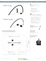
NW301 Twister
NW302 Springer
POSITION AND TRAINING ZONE:
POSITION UND TRAININGSZONE:
See separate page with the
preparatory work for surface mount
installation.
• Install onto surface.
• Assemble and line up.
• Place on concrete.
• Mark position of bolt holes.
• Fasten each base plate with
4 x M12 bolts.
0,50m
0,50m
Auf der separaten Seite finden Sie
Angaben zu vorbereitenden Maßnahmen
für eine Installation an der Oberfläche.
• Wird an der Oberfläche installiert.
• Bauen Sie zunächst die Teile
zusammen und stellen Sie sie auf.
• Platzieren Sie sie auf dem Beton.
• Markieren Sie die Positionen der
Schraubenlöcher.
• Fixieren Sie jede Basisplatte mit
4 x M12 Schwerlastdübeln.
CONCRETE DEPTH:
BETON TIEFE:
PART LIST:
BESTANDTEIL LISTE:
16 x M12
BASE PLATE:
BASISPLATTE:
25 x 25cm / 10” x 10”
CONCRETE
BLOCK /
BETONBLOCK
0,50m/ 20”
0,50m/ 20”
18,5m
2
/ 199 ft
2
Training zone =
1,5m /59”
2,45m / 96,5”
0,75m /29,5”
0,9m /35,5”
5,45m / 214,6”
4,20m /165”
2,10m /82,5”

INSTALLATION MANUAL · SURFACE MOUNT · OBERFLÄCHE
www.norwell.dk · info@norwell.dk COPYRIGHT © 2017 Norwell A/S
16
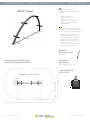
NW401 Stretch
POSITION AND TRAINING ZONE:
POSITION UND TRAININGSZONE:
See separate page with the
preparatory work for surface mount
installation.
• Install onto surface.
• Assemble and line up.
• Place on concrete.
• Mark position of bolt holes.
• Fasten each base plate with
4 x M12 bolts.
0,50m
0,50m
Auf der separaten Seite finden Sie
Angaben zu vorbereitenden Maßnahmen
für eine Installation an der Oberfläche.
• Wird an der Oberfläche installiert.
• Bauen Sie zunächst die Teile
zusammen und stellen Sie sie auf.
• Platzieren Sie sie auf dem Beton.
• Markieren Sie die Positionen der
Schraubenlöcher.
• Fixieren Sie jede Basisplatte mit
4 x M12 Schwerlastdübeln.
CONCRETE DEPTH:
BETON TIEFE:
PART LIST:
BESTANDTEIL LISTE:
8 x M12
BASE PLATE:
BASISPLATTE:
25 x 25cm / 10” x 10”
CONCRETE
BLOCK /
BETONBLOCK
0,50m/ 20”
0,50m/ 20”
14m
2
/ 150,5 ft
2
Training zone =
5,45m / 214,6”
1,50m /59”
2,45m / 96,5”
1,70m /67”
3,40m /134”
0,5m /20”
0,5m /20”

INSTALLATION MANUAL · SURFACE MOUNT · OBERFLÄCHE
www.norwell.dk · info@norwell.dk COPYRIGHT © 2017 Norwell A/S
17
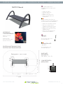
NW501 Bench
POSITION AND TRAINING ZONE:
POSITION UND TRAININGSZONE:
See separate page with the
preparatory work for surface mount
installation.
• Install onto surface.
• Assemble and line up.
• Place on concrete.
• Mark position of bolt holes.
• Fasten each base plate with
4 x M12 bolts.
PART LIST:
16 x M12
4 x sets of Nut caps, round
4 x M10 x110 bolts
Auf der separaten Seite finden Sie
Angaben zu vorbereitenden Maßnahmen
für eine Installation an der Oberfläche.
• Wird an der Oberfläche installiert.
• Bauen Sie zunächst die Teile
zusammen und stellen Sie sie auf.
• Platzieren Sie sie auf dem Beton.
• Markieren Sie die Positionen der
Schraubenlöcher.
• Fixieren Sie jede Basisplatte mit
4 x M12 Schwerlastdübeln.
CONCRETE DEPTH:
BETON TIEFE:
BASE PLATE:
BASISPLATTE:
25 x 25cm / 10” x 10”
4 x Set Hutmuttern, rund
4 x M10 x110 Bolzen
BESTANDTEIL LISTE:
16 x M12
0,50m
0,50m
CONCRETE
BLOCK /
BETONBLOCK
0,50m/ 20”
0,50m/ 20”
ASSEMBLING:
ZUSAMMENBAUEN:
Always secure bolts
with Loctite.
Sicheren Sie die
Bolzen immer durch das
Benetzten mit Loctite.
0,5m /20”
16,5m
2
/ 177,5 ft
2
Training zone =
0,5m /20”
1,5m /59”0,88m /34,6”
1,50m / 59”
4,80m / 189”
3,90m /153,5”
1,80m / 71”

INSTALLATION MANUAL · SURFACE MOUNT · OBERFLÄCHE
www.norwell.dk · info@norwell.dk COPYRIGHT © 2017 Norwell A/S
18
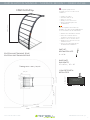
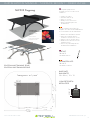
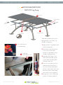
NW502 Pingpong
POSITION AND TRAINING ZONE:
POSITION UND TRAININGSZONE:
See separate page with the
preparatory work for surface mount
installation.
• Install onto surface.
• Assemble and line up.
• Place on concrete.
• Mark position of bolt holes.
• Fasten each base plate with
4 x M12 bolts.
Auf der separaten Seite finden Sie
Angaben zu vorbereitenden Maßnahmen
für eine Installation an der Oberfläche.
• Wird an der Oberfläche installiert.
• Bauen Sie zunächst die Teile
zusammen und stellen Sie sie auf.
• Platzieren Sie sie auf dem Beton.
• Markieren Sie die Positionen der
Schraubenlöcher.
• Fixieren Sie jede Basisplatte mit
4 x M12 Schwerlastdübeln.
CONCRETE DEPTH:
BETON TIEFE:
BASE PLATE:
BASISPLATTE:
25 x 25cm / 10” x 10”
0,50m
0,50m
CONCRETE
BLOCK /
BETONBLOCK
0,50m/ 20”
0,50m/ 20”
ASSEMBLING:
ZUSAMMENBAUEN:
Always secure bolts
with Loctite.
Sicheren Sie die
Bolzen immer durch das
Benetzten mit Loctite.
1,25m /49”
21 m
2
/ 226 ft
2
Training zone =
0,5m /20”
0,5m /20”
2,00m / 78,7”
1,65m /65”
5,50m / 216,5”
1,73m / 68”
4,55m /179”
PART LIST:
16 x M12
10 x M10 x12 bolts
BESTANDTEIL LISTE:
10 x M10 x 12 Bolzen
16 x M12

INSTALLATION MANUAL · SURFACE MOUNT · OBERFLÄCHE
www.norwell.dk · info@norwell.dk COPYRIGHT © 2017 Norwell A/S
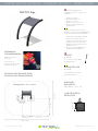
19
INSTRUCTION FOR ASSEMBLING
NW502 Ping Pong
See separate page for position, zone
and concrete area requirements.
1 Bolt the 5 table top supports
to the side frames.
2 Place the net right in the center
vertically and horizontally.
It has the same width as the
table tops.
3 Add the Multi Glue on top of
all supports, both upper frames
and on top of the foot of the
net.
4 Two people hold one table top
over the frame and all the way
up to the net. Make sure to
center the top on all sides,
lower down and press the top
against frame and supports.
5 Repeat with the next table top.
Table top
supports
Foot of
the net
The net
Always secure bolts
with Loctite.
Add the supplied
Multi Glue.
1
2
3
3
1
The side frames
Table top
supports
Foot of
the net
The net

INSTALLATION MANUAL · SURFACE MOUNT · OBERFLÄCHE
www.norwell.dk · info@norwell.dk COPYRIGHT © 2017 Norwell A/S
20
1
2
3
3
1
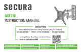
MONTAGEANLEITUNG
NW502 Ping Pong
Siehe die separate Seite für Anfor-
derungen der Position, der Zone
und des Fundamentes.
1 Befestige die 5 Tischplattenstützen
an das Seitengestell.
2 Platziere das Netz Vertikal und
Horizontal im Zentrum des
Gestells. Es hat dieselbe Breite
wie die Tischplattenstützen.
3 Trage den Multi-Klebstoff auf
allen Oberflächen der Stützen,
sowie auf der Oberfläche der
Füße des Netzes auf.
4 Zwei Personen halten eine Tisch-
platte über das Gestell bis hin
zum Netz und zentrieren diese
akkurat zu allen Seiten. Nun wird
die Platte auf das Gestell abge-
senkt und mit Druck angebracht.
5 Der gleiche Prozess wird mit der
zweiten Tischplatte wiederholt.
Tischplattenstütze
Fuß
des Netzes
Das Netz
Das Seitengestell
Die Bolzen stets mit
Loctite befestigen.
Trage den
Multi-Klebstoff auf.
Seite laden ...
-
 1
1
-
 2
2
-
 3
3
-
 4
4
-
 5
5
-
 6
6
-
 7
7
-
 8
8
-
 9
9
-
 10
10
-
 11
11
-
 12
12
-
 13
13
-
 14
14
-
 15
15
-
 16
16
-
 17
17
-
 18
18
-
 19
19
-
 20
20
-
 21
21


Norwell NW503 Sign Installationsanleitung
- Typ
- Installationsanleitung
Sonstige Unterlagen
-
M-Cab 7000403 Datenblatt
-
Amica BK3195.4DFVCAA Installationsanleitung
-
Amica BK3165.4 Installationsanleitung
-
Rotary SPOA3TS-5-EH2-MB Bedienungsanleitung
-
PERLESMITH PSML1 Installationsanleitung
-
-
Hilti MSP-Solarpark Bedienungsanleitung
-
-
-
 Secura QSF210 Installationsanleitung
