
Guide d'exploitation
User's manual
Bedienungsanleitung
Guía de explotación
Merlin Gerin
Telemecanique
Square D
Modicon
Altivar 18
Telemecanique
variateurs de vitesse pour
moteurs asynchrones,
variable speed controllers
for asynchronous motors,
Frequenzumrichter
für Drehstrom-Asynchronmotoren,
variadores de velocidad
para motores asíncronos.

Seite laden ...
Seite laden ...

4
F
R
A
N
Ç
A
I
S
Seite laden ...

6
F
R
A
N
Ç
A
I
S
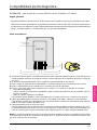
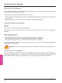
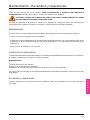
Vérifications préliminaires
Sortir l'Altivar 18 de son emballage, et vérifier qu'il n'a pas été endommagé pendant le transport. S'assurer
que la référence du variateur inscrite sur l'étiquette est conforme au bordereau de livraison correspondant
au bon de commande.
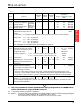
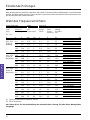
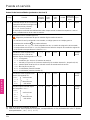
Choix du variateur
Réseau Moteur Altivar 18
Tension Courant Puissance Courant Courant Puis- Référence Masse
d'alimen- de ligne (1) indiquée de sortie transi- sance
tation à U1 à U2 sur plaque perma- toire dissipée
ment maxi (2) à la
U1…U2 charge
nominale
V AAkWHPAAW kg
200…240 4,4 3,9 0,37 0,5 2,1 3,1 23 ATV-18U09M2 1,5
50/60 Hz
monophasé 7,6 6,8 0,75 1 3,6 5,4 39 ATV-18U18M2 1,5
13,9 12,4 1,5 2 6,8 10,2 60 ATV-18U29M2 2,1
19,4 17,4 2,2 3 9,6 14,4 78 ATV-18U41M2 2,8
200…230 16,2 14,9 3 – 12,3 18,5 104 ATV-18U54M2 3,3
50/60 Hz
triphasé 20,4 18,8 4 5 16,4 24,6 141 ATV-18U72M2 3,3
28,7 26,5 5,5 7,5 22 33 200 ATV-18U90M2 7,8
38,4 35,3 7,5 10 28 42 264 ATV-18D12M2 7,8
380…460 2,9 2,7 0,75 1 2,1 3,2 24 ATV-18U18N4 2
50/60 Hz
triphasé 5,1 4,8 1,5 2 3,7 5,6 34 ATV-18U29N4 2,1
6,8 6,3 2,2 3 5,3 8 49 ATV-18U41N4 3,1
9,8 8,4 3 – 7,1 10,7 69 ATV-18U54N4 3,3
12,5 10,9 4 5 9,2 13,8 94 ATV-18U72N4 3,3
16,9 15,3 5,5 7,5 11,8 17,7 135 ATV-18U90N4 8
21,5 19,4 7,5 10 16 24 175 ATV-18D12N4 8
31,8 28,7 11 15 22 33 261 ATV-18D16N4 12
42,9 38,6 15 20 29,3 44 342 ATV-18D23N4 12
(1) Valeur typique sans inductance additionnelle.
(2) Pendant 60 secondes.
L'Altivar 18 a été conçu pour alimenter les moteurs d'une puissance adaptée à chacun de ses
calibres.
Seite laden ...
Seite laden ...

9
F
R
A
N
Ç
A
I
S
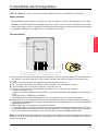
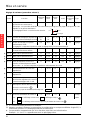
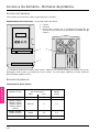
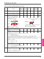
Encombrements - Précautions de montage
Encombrements
ATV18iiii
ATV18 abcGHØ
U09M2, U18M2 112 182 121 100 170 5
U29M2, U18N4, U29N4 149 184 157 137 172 5
U41M2, U54M2, U72M2, U41N4, U54N4, U72N4 185 215 158 171 202 6
U90M2, D12M2, U90N4, D12N4 210 300 170 190 280 7
D16N4, D23N4 245 390 190 225 370 10
Précautions de montage
Installer l'appareil verticalement.
Eviter de le placer à proximité d'éléments chauffants.
Respecter un espace libre suffisant pour assurer la circulation de l'air nécessaire au refroidissement, qui se
fait par ventilation du bas vers le haut.
IP2O : retirer l'obturateur de la partie supérieure du capot (pellicule autocollante).
Débit des ventilateurs
ATV-18U09M2, U18M2, U18N4 : non ventilés.
ATV-18U29M2, U29N4 : 0,25 m
3
/minute.
ATV-18U41M2, U54M2, U72M2, U41N4, U54N4, U72N4 :
0,75 m
3
/minute.
ATV-18U90M2, D12M2, U90N4, D12N4, D16N4, D23N4 :
1,3 m
3
/minute.
c
b
a
G
Ø
==
H==
≥ 50 ≥ 50
≥ 100
≥ 100
Seite laden ...
Seite laden ...

12
F
R
A
N
Ç
A
I
S
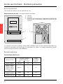
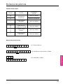
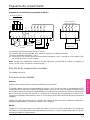
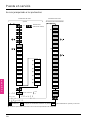
Accès aux borniers - Borniers puissance
Accès aux borniers
Pour accéder aux borniers, ôter le capot fixé par 2 vis.
Emplacement des borniers : à la partie inférieure de l'Altivar.
1 - Contrôle
2 - Puissance
3 - Borne pour raccordement d'un conducteur de protection de
section 10 mm
2
conformément à EN50178 (courant de fuite
à la terre)
Les variateurs sont munis de trappes "passe-câble" métalliques avec des trous équipés d'obturateurs en
caoutchouc perforables pour le passage et la protection des câbles. Ces trappes métalliques peuvent
recevoir des presse-étoupes CEM métalliques.
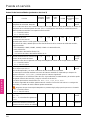
Borniers puissance
Caractéristiques des bornes
Capacité maximale Couple
Altivar ATV-18 de raccordement de serrage
AWG mm
2
en Nm
U09M2, U18M2 AWG14 2,5 1
U29M2, U41M2
U54M2, U72M2
U18N4, U29N4 AWG10 6 1,2
U41N4, U54N4
U72N4
U90M2, D12M2,
U90N4, D12N4
AWG8 10 2,4
D16N4, D23N4 AWG6 16 4
DATA ENT
13
2

13
F
R
A
N
Ç
A
I
S
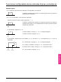
Borniers puissance
Fonction des bornes
Bornes Fonction
Pour Altivar
ATV-18
L1
L2 Alimentation
Tous calibres
L3
Puissance
Triphasés seuls
s
Borne de masse
Tous calibres
de l'Altivar
Ne pas utiliser Tous calibres
PA Sortie vers la
Tous calibres
PB résistance de freinage
U
Sorties vers
V Tous calibres
W
le moteur
s
Borne de masse
Tous calibres
de l'Altivar
Disposition des bornes
ATV-18 monophasés
ATV-18 triphasés sauf D16N4 et D23N4
ATV-18D16N4 et D23N4
L1 L2 L3
PA PB
s PA PB U V
L1 L2 L3 s U V W s
W s
L1 L2 s PA PB U V W s
Seite laden ...
Seite laden ...
Seite laden ...
Seite laden ...
Seite laden ...
Seite laden ...
Seite laden ...
Seite laden ...
Seite laden ...

23
F
R
A
N
Ç
A
I
S
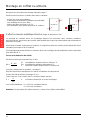
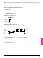
Mise en service
Utilisation du terminal intégré
Exemple 1 : réglage de rampe
Exemple 2 : accès aux paramètres de deuxième niveau
Exemple 3 : configuration de la sortie logique
bFr
ACC “0
ACC
{8 {8
dEC
DATA ENT
DATA
(1 clignotement)
Etc.
(1 clignotement)
Etc.
FLt
L2A no
L2A
YES YES
UFt
DATA ENT
DATA
(1 clignotement)
Etc.
LI4
LO SrA
LO
FtA FtA
AIC
DATA ENT
DATA
accès au 2ème niveau

24
F
R
A
N
Ç
A
I
S
rdYrdY 4{54{5
FrHFrH
LCrLCr
CPUCPU
rFrrFr
ULnULn
ACC
dEC
LSP
HSP
FLG
ItH
JPF
IdC
tdC
UFr
bFr
UFt
tUn
UnS
FrS
tFr
SLP
LI2
tLS
LI3
LI4
Atr
FCS
LO
AIC
CrL
SPr
SFr
StP
brA
FLtFLt
L2A
L2A = YES
L2A
= no
L2A = YES
SP3
SP4
JOG
Fdt
rPG
rIG
FbS
*
*
*
*
*
*
*
*
*
*
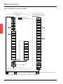
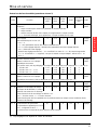
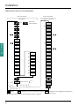
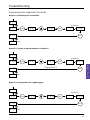
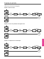
Mise en service
Accès hiérarchisé aux paramètres
Paramètres de niveau 1
Réglages
ou
Etat initial
(affichage normal)
Paramètres de niveau 2
Extensions de fonctionnalités
Accès au niveau 2
YES
no
Affichage
Configuration modifiable seulement à l'arrêt
Réglage modifiable à l'arrêt et en marche
Paramètre présenté seulement si la fonction correspondante est configurée
Seite laden ...
Seite laden ...
Seite laden ...
Seite laden ...
Seite laden ...
Seite laden ...
Seite laden ...
Seite laden ...
Seite laden ...
Seite laden ...

36
E
N
G
L
I
S
H

37
E
N
G
L
I
S
H
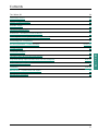
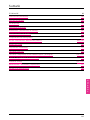
Contents
The "Altivar 18" 34
Preliminary checks 38
Choice of speed controller 38
Available torque 39
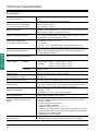
Technical characteristics 40
Dimensions - Mounting recommendations 41
Mounting in a wall-fixing or floor standing enclosure 42
Electromagnetic compatibility 43
Accessing terminals - Power terminals 44 and 45
Control terminals 46
Connection diagram 47
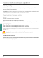
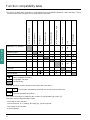
Functions which do not require adjustment 48
Logic and analog input functions which can be configured 49 to 51
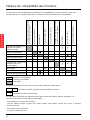
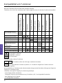
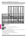
Function compatibility table 52
Installation 53 to 62
Maintenance - Replacement and repairs 63
Maintenance assistance 64

38
E
N
G
L
I
S
H
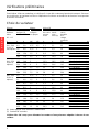
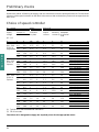
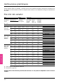
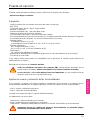
Preliminary checks
Remove the Altivar 18 from its packaging, and check that it has not been damaged in transit. Check that the
reference of the speed controller on the label is the same as that on the delivery note and corresponds to the
order form.
Choice of speed controller
A.C. supply Motor Altivar 18
Power Line Power Permanent Maximum Power Reference Weight
supply current (1) indicated output transient dissipated
voltage at U1 at U2 on plate current current (2) at nominal
load
U1…U2
V AAkWHPAAW kg
200…240 4.4 3.9 0.37 0.5 2.1 3.1 23 ATV-18U09M2 1.5
50/60 Hz
single phase 7.6 6.8 0.75 1 3.6 5.4 39 ATV-18U18M2 1.5
13.9 12.4 1.5 2 6.8 10.2 60 ATV-18U29M2 2.1
19.4 17.4 2.2 3 9.6 14.4 78 ATV-18U41M2 2.8
200…230 16.2 14.9 3 – 12.3 18.5 104 ATV-18U54M2 3.3
50/60 Hz
3-phase 20.4 18.8 4 5 16.4 24.6 141 ATV-18U72M2 3.3
28.7 26.5 5.5 7.5 22 33 200 ATV-18U90M2 7.8
38.4 35.3 7.5 10 28 42 264 ATV-18D12M2 7.8
380…460 2.9 2.7 0.75 1 2.1 3.2 24 ATV-18U18N4 2
50/60 Hz
3-phase 5.1 4.8 1.5 2 3.7 5.6 34 ATV-18U29N4 2.1
6.8 6.3 2.2 3 5.3 8 49 ATV-18U41N4 3.1
9.8 8.4 3 – 7.1 10.7 69 ATV-18U54N4 3.3
12.5 10.9 4 5 9.2 13.8 94 ATV-18U72N4 3.3
16.9 15.3 5.5 7.5 11.8 17.7 135 ATV-18U90N4 8
21.5 19.4 7.5 10 16 24 175 ATV-18D12N4 8
31.8 28.7 11 15 22 33 261 ATV-18D16N4 12
42.9 38.6 15 20 29.3 44 342 ATV-18D23N4 12
(1) Typical value without additional inductance.
(2) For 60 seconds.
The Altivar 18 is designed to supply the required power for the appropriate motor.

39
E
N
G
L
I
S
H
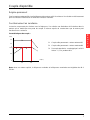
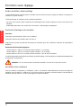
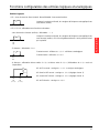
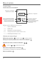
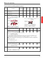
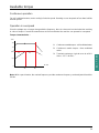
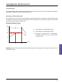
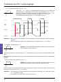
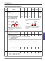
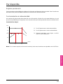
Available torque
Continuous operation
For self-ventilated motors, motor cooling is linked to speed. Derating occurs at speeds of less than half the
nominal speed.
Operation in overspeed
Since the voltage can no longer change with the frequency, there is a decrease in motor induction resulting
in a loss of torque. Consult the manufacturer to find out whether the machine can operate in overspeed.
Torque characteristics :
1 Continuous usable torque : self-ventilated motor
2 Continuous usable torque : force-ventilated
motor
3 Transient overtorque : typical curve at ± 10 %
Value : 1.5 Tn for 60 s
Note : With a special motor, the nominal frequency and the maximum frequency can be adjusted from 40 to
320 Hz.
0
N (Hz)
0,5
25
30
50
60
1
3
21
1
0,95
1,5
T/Tn
1,2
Seite laden ...

41
E
N
G
L
I
S
H
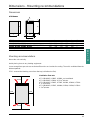
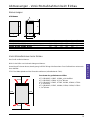
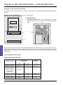
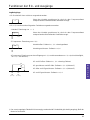
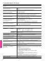
Dimensions - Mounting recommendations
Dimensions
ATV18iiii
ATV18 abcGHØ
U09M2, U18M2 112 182 121 100 170 5
U29M2, U18N4, U29N4 149 184 157 137 172 5
U41M2, U54M2, U72M2, U41N4, U54N4, U72N4 185 215 158 171 202 6
U90M2, D12M2, U90N4, D12N4 210 300 170 190 280 7
D16N4, D23N4 245 390 190 225 370 10
Mounting recommendations
Mount the unit vertically.
Avoid placing close to any heating equipment.
Leave enough free space to ensure that sufficient air can circulate for cooling. The unit is ventilated from the
bottom upwards.
IP2O : remove the blanking cover from the top (self-adhesive film).
Ventilation flow rate
ATV-18U09M2, U18M2, U18N4 : not ventilated.
ATV-18U29M2, U29N4 : 0.25 m
3
/minute.
ATV-18U41M2, U54M2, U72M2, U41N4, U54N4, U72N4 :
0.75 m
3
/minute.
ATV-18U90M2, D12M2, U90N4, D12N4, D16N4, D23N4 :
1.3 m
3
/minute.
c
b
a
G
Ø
==
H==
≥ 50 ≥ 50
≥ 100
≥ 100
Seite laden ...
Seite laden ...

44
E
N
G
L
I
S
H
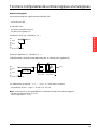
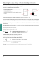
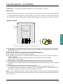
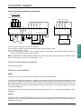
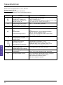
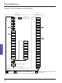
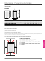
Accessing terminals - Power terminals
Accessing terminal blocks
To access terminal blocks, remove cover fixed by 2 screws.
Terminal blocks : on the lower part of the Altivar.
1 - Control
2 - Power
3 - Terminal for connecting a protection conductor with a 10 mm
2
cross section in accordance with EN50178 (earth leakage
current)
Speed controllers are fitted with metal gland plates equipped with rubber blanking plugs which can be
perforated to enable cables to be passed through them and also to protect the cables.The gland plates can
take EMC metal cable glands.
Power terminals
Terminal characteristics
Maximum connection Tightening
Altivar ATV-18 capacity torque
AWG mm
2
in Nm
U09M2, U18M2 AWG14 2.5 1
U29M2, U41M2
U54M2, U72M2
U18N4, U29N4 AWG10 6 1.2
U41N4, U54N4
U72N4
U90M2, D12M2,
U90N4, D12N4
AWG8 10 2.4
D16N4, D23N4 AWG6 16 4
DATA ENT
13
2

45
E
N
G
L
I
S
H
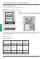
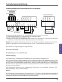
Power terminals
Function of terminals
Terminals Function
For Altivar
ATV-18
L1
L2 Power
All ratings
L3
supply
3-phase only
s
Altivar
All ratings
ground terminal
Do not use All ratings
PA Output to
All ratings
PB brake resistor
U
Output to
V All ratings
W
the motor
s
Altivar
All ratings
ground terminal
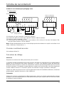
Terminal connections
L1 L2 L3
PA PB
s PA PB U V
L1 L2 L3 s U V W s
W s
L1 L2 s PA PB U V W s
ATV-18 single phase
ATV-18 3-phase except D16N4 and D23N4
ATV-18D16N4 and D23N4
Seite laden ...
Seite laden ...
Seite laden ...
Seite laden ...
Seite laden ...
Seite laden ...
Seite laden ...
Seite laden ...
Seite laden ...

55
E
N
G
L
I
S
H
Installation
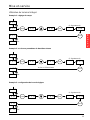
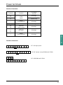
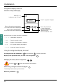
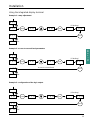
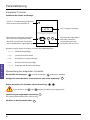
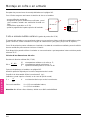
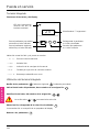
Using the integrated display terminal
Example 1 : ramp adjustment
Example 2 : access to second level parameters
Example 3 : configuration of the logic output
bFr
ACC “0
ACC
{8 {8
dEC
DATA ENT
DATA
(1 flashing)
Etc.
(1 flashing)
Etc.
FLt
L2A no
L2A
YES YES
UFt
DATA ENT
DATA
(1 flashing)
Etc.
LI4
LO SrA
LO
FtA FtA
AIC
DATA ENT
DATA
access to second level
Seite laden ...
Seite laden ...

58
E
N
G
L
I
S
H
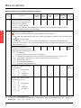
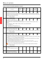
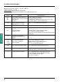
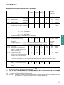
Installation
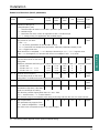
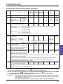
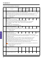
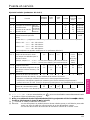
Adjustment of speed controller (level 1 parameters)
Factory
Maximum Minimum
Resolution
Code Function
preset value value
Unit (
minimum
Type
increment)
JPF Cancellation of a critical speed 0 HSP 0 Hz 0.1 Adjust.
which leads to mechanical
resonance : it is possible to prevent prolonged operation in a 2 Hz frequency range, which can be
adjusted anywhere between LSP and HSP.
Factory preset of 0 deactivates the function.
Idc Automatic DC injection braking 0.7 I
N
I
N
0.25
ItH A 0.1 Adjust.
current when stopped (1) (1)
tdc Automatic injection braking time 0.5 25.5 0 s 0.1 Adjust.
when stopped.
Setting of 0 cancels the injection when stopped, setting to 25.5 makes this permanent (2).
UFr Parameter enabling the torque 20 100 0 1 Adjust.
to be optimized at a very low speed
SP3 3rd preset speed S HSP LSP Hz 0.1 Adjust.
SP4 4th preset speed 25 HSP LSP Hz 0.1 Adjust.
JOG Setpoint in "jog" operation 10 10 0 Hz 0.1 Adjust.
Fdt Frequency threshold associated with 0 HSP LSP Hz 0.1 Adjust.
the "frequency threshold reached"
function of output LO. This threshold comprises an anti-repeat hysteresis of 0.2 Hz.
rPG Proportional gain of the PI regulator 1 10ø0 ø01 ø01 Adjust.
function
rIG Integral gain of the PI regulator 1 10ø0 ø01 1/s ø01 Adjust.
function
FbS Multiplication coefficient of feedback of 1 10ø0 ø1 ø1 Adjust.
PI regulator function, associated
with analog input AIC or AI2.
FLt Display of the last fault which occurred, Display
by pressing the
DATA
key.
When no fault has occurred the display reads : nErr .
L2A Access to level 2 parameters. no YES no Configu-
no : no → the next display will be rdY (initial display) if
ration
yes : YES → the next display will be the first parameter of level 2 if
JPF
2 Hz
f
Setpoint
(1) I
N
= speed controller permanent output current.
(2) Warning, the configuration parameters cannot be modified during braking. Set 25.5 s as the last
operation if permanent braking is required.
*
These parameters only appear if the associated functions are selected.
Example : SP3 and SP4 only appear as a factory preset.
*
*
*
*
*
*
*
Seite laden ...
Seite laden ...

61
E
N
G
L
I
S
H
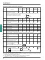
Installation
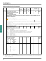
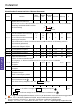
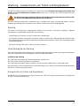
Extension of functions (level 2 parameters)
Factory
Maximum Minimum
Resolution
Code Function
preset value value
Unit (
minimum
Type
increment)
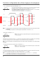
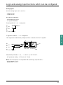
LI3 Reassignment of logic input PS2 " " Configu-
LI3 : same as LI2 ration
LI4 Reassignment of logic input PS4 " " Configu-
LI4 : same as LI2 ration
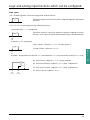
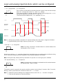
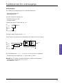
LO Assignment of the logic input SrA SrA FtA Configu-
1) SrA : speed reference reached ration
by the motor, with a threshold of
± 2,5 Hz 2) FtA : frequency threshold crossed (Fdt)
Assigning FtA causes the
Fdt setting to appear in level 1 parameters.
Note : If the reference is less than Set this parameter
0.5 Hz, the output LO is reset to 0.
AIC Assignment of the analog input
AIC/AI2.
If the logic inputs are not assigned SAI PIF SAI Configu-
to the preset speeds (PS2 - PS4) ration
or to jog operation (JOG):
- SAI : Summing with AI1
- PIF : PI regulator feedback.
This configuration automatically assigns input AI1 as the regulator reference and displays the
adjustments in the level 1 parameters : rPG, rIG, FbS.
Note : This configuration is only possible if the user has previously been using the following
configurations, in the order :
1) LI4 = OFF or FSt
2) LI3 = OFF or dCI
3) LI2 = OFF or rrS
If a logic input is assigned SAI SAI SAI Configu-
to the preset speeds ration
(PS2 - PS4) or to jog operation (JOG):
- SAI : Summing with AI1
CrL Configuration of input AIC/AI2 : ø0 ‘0 ø0 mA Configu-
ration
- ø0 : AIC : 0 - 20 mA / AI2 : 0 + 10 V
- ‘0 : AIC : 4 - 20 mA / AI2 : 2 + 10 V
+2,5 Hz
+2,5 Hz
-2,5 Hz
-2,5 Hz
Reference
Speed
Frequency
Hysteresis
0.2 Hz
Threshold Fdt
LO
LO
Seite laden ...
Seite laden ...

64
E
N
G
L
I
S
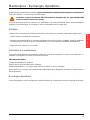
H
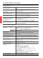
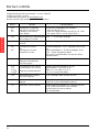
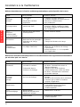
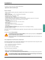
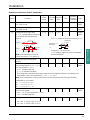
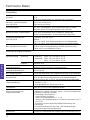
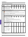
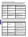
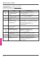
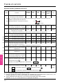
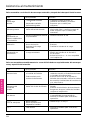
Maintenance assistance
Faults which can be reset with the automatic restart function, after the cause of the fault has been
corrected
Fault Probable cause Remedies
OHF -I
2
t too high - Check the motor load, the speed controller
speed controller or ventilation and the environment.
overload - speed controller temperature Wait for it to cool before restarting.
too high
OLF -I
2
t motor too high - Check the setting of the motor thermal
motor overload protection, and check the motor load.
Wait for it to cool before restarting.
OSF - mains voltage too high - Check the mains voltage.
overvoltage - mains interference
in steady state
or during acceleration
USF - Mains supply voltage too low - Check the voltage and the voltage parameter.
under voltage - Momentary drop in voltage - Reset.
- Weakened load resistance - Change the load resistance.
ObF - Braking too abrupt - Increase the deceleration time.
overvoltage or driving load - Add brake resistor if necessary.
on deceleration - Activate the function brA if it is compatible
with the application.
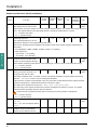
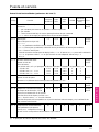
Faults which cannot be automatically reset. The cause of the fault must be corrected before resetting
by switching the controller off and then on again
Fault Probable cause Remedies
OCF - Short-circuit or earthing - Having disconnected the speed controller,
overcurrent at speed controller output check the connection cables, motor isolation
and state of the windings.
- Overcurrent in the brake - Check the resistor selected.
resistor Having disconnected the speed controller,
check the connection cables, insulation of
the resistor and its ohmic value.
dbF - Exceeding the capacity - Check the brake resistor selected.
braking circuit of the braking circuit Check the ohmic resistance value.
overload Ensure that the speed controller rating is
suitable for the application.
InF - Internal fault - Check the environment
internal fault (electromagnetic compatibility).
- Return the speed controller for
servicing/repair.
tnF - Special motor - Use L or P mode.
auto-tune error - Power motor not adapted to
the speed controller
EEF - Internal fault - Return the speed controller for
servicing/repair.
Seite laden ...
Seite laden ...
Seite laden ...
Seite laden ...
Seite laden ...
Seite laden ...
Seite laden ...
Seite laden ...
Seite laden ...
Seite laden ...
Seite laden ...
Seite laden ...
Seite laden ...
Seite laden ...
Seite laden ...
Seite laden ...
Seite laden ...
Seite laden ...
Seite laden ...
Seite laden ...
Seite laden ...
Seite laden ...
Seite laden ...
Seite laden ...
Seite laden ...
Seite laden ...
Seite laden ...
Seite laden ...
Seite laden ...
Seite laden ...
Seite laden ...
Seite laden ...
Seite laden ...
Seite laden ...
Seite laden ...
Seite laden ...
Seite laden ...
Seite laden ...
Seite laden ...
Seite laden ...
Seite laden ...
Seite laden ...
Seite laden ...
Seite laden ...
Seite laden ...
Seite laden ...
Seite laden ...
Seite laden ...
Seite laden ...
Seite laden ...
Seite laden ...
Seite laden ...
Seite laden ...
Seite laden ...
Seite laden ...
Seite laden ...
Seite laden ...
Seite laden ...
Seite laden ...
Seite laden ...
Seite laden ...
Seite laden ...
Seite laden ...
-
 1
1
-
 2
2
-
 3
3
-
 4
4
-
 5
5
-
 6
6
-
 7
7
-
 8
8
-
 9
9
-
 10
10
-
 11
11
-
 12
12
-
 13
13
-
 14
14
-
 15
15
-
 16
16
-
 17
17
-
 18
18
-
 19
19
-
 20
20
-
 21
21
-
 22
22
-
 23
23
-
 24
24
-
 25
25
-
 26
26
-
 27
27
-
 28
28
-
 29
29
-
 30
30
-
 31
31
-
 32
32
-
 33
33
-
 34
34
-
 35
35
-
 36
36
-
 37
37
-
 38
38
-
 39
39
-
 40
40
-
 41
41
-
 42
42
-
 43
43
-
 44
44
-
 45
45
-
 46
46
-
 47
47
-
 48
48
-
 49
49
-
 50
50
-
 51
51
-
 52
52
-
 53
53
-
 54
54
-
 55
55
-
 56
56
-
 57
57
-
 58
58
-
 59
59
-
 60
60
-
 61
61
-
 62
62
-
 63
63
-
 64
64
-
 65
65
-
 66
66
-
 67
67
-
 68
68
-
 69
69
-
 70
70
-
 71
71
-
 72
72
-
 73
73
-
 74
74
-
 75
75
-
 76
76
-
 77
77
-
 78
78
-
 79
79
-
 80
80
-
 81
81
-
 82
82
-
 83
83
-
 84
84
-
 85
85
-
 86
86
-
 87
87
-
 88
88
-
 89
89
-
 90
90
-
 91
91
-
 92
92
-
 93
93
-
 94
94
-
 95
95
-
 96
96
-
 97
97
-
 98
98
-
 99
99
-
 100
100
-
 101
101
-
 102
102
-
 103
103
-
 104
104
-
 105
105
-
 106
106
-
 107
107
-
 108
108
-
 109
109
-
 110
110
-
 111
111
-
 112
112
-
 113
113
-
 114
114
-
 115
115
-
 116
116
-
 117
117
-
 118
118
-
 119
119
-
 120
120
-
 121
121
-
 122
122
-
 123
123
-
 124
124
-
 125
125
-
 126
126
-
 127
127


Schneider Electric ALTIVAR 18 Benutzerhandbuch
- Typ
- Benutzerhandbuch
- Dieses Handbuch ist auch geeignet für
in anderen Sprachen
Verwandte Papiere
Sonstige Unterlagen
-
Eurotherm ATV312 Bedienungsanleitung
-
-
-
-
-
Sammic BE-10/C Benutzerhandbuch
-
ABB ACSM1-04 Series Quick Installation Manual
-
 Speck pumpen SPR-I 030 Bedienungsanleitung
-
ABB ACS880-01 Series Quick Installation Manual
-
