
ABB Drives
Quick Installation Guide
ACSM1-04/04Lx Drive Modules (55 to 160 kW)
English. . . . . . . . . . . . . . . . . . . . . 3
Deutsch . . . . . . . . . . . . . . . . . . . 11
Español . . . . . . . . . . . . . . . . . . . 19
Français. . . . . . . . . . . . . . . . . . . 27
Italiano. . . . . . . . . . . . . . . . . . . . 35
Suomi . . . . . . . . . . . . . . . . . . . . 43
Svenska. . . . . . . . . . . . . . . . . . . 51
中文 . . . . . . . . . . . . . . . . . . . . . . 59
3AFE68971853 REV D
Effective: 20.02.2009
© 2009 ABB Oy. All rights reserved.


Quick installation guide - ACSM1-04/04Lx
3
Quick installation guide -
ACSM1-04/04Lx
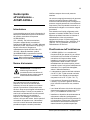
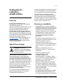
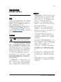
Introduction
This guide contains the very basic information
about the mechanical and electrical installation
of the ACSM1-04/04Lx drive module (55 to
160 kW). For complete documentation, see
either ACSM1-04 Drive Modules (55 to
110 kW) Hardware Manual (code:
3AFE68912130 [English]) or ACSM1-04Lx
Liquid Cooled Drive Modules (55 to 160 kW)
Hardware Manual (code: 3AUA0000022083
[English]) depending on drive type. Both are
available at www.ab
b.com/drives. In this guide,
the manual is referred to as the Hardware
Manual.
Safety instructions
WARNING! All electrical installation
and maintenance work on the drive
should be carried out by qualified
electricians only.
Never work on the drive, the braking chopper
circuit, the motor cable or the motor when input
power is applied to the drive. After
disconnecting input power, always wait for 5
minutes to let the intermediate circuit
capacitors discharge before you start working
on the drive, control cabling, motor or motor
cable. Even when input power is not applied to
the drive, externally supplied control circuits
may carry dangerous voltages. Always ensure
by measuring that no voltage is actually
present.
A rotating permanent magnet motor can
generate a dangerous voltage. Lock the motor
shaft mechanically before connecting a
permanent magnet motor to the drive, and
before doing any work on a drive system
connected to a permanent magnet motor.
With ACSM1-04Lx, beware of hot coolant. Do
not work on the cooling system until the
pressure is lowered down by stopping the
pumps. High-pressure hot coolant (max.
1000 kPa, 55 °C [145 PSI, 131 °F]) is present
in the cooling circuit when it is in operation.
Planning the installation
• The ACSM1-04/04Lx is an IP20 (UL open
type) drive to be used in a heated, indoor
controlled environment. The drive must be
installed in clean air according to enclosure
classification. Cooling air must be clean, free
from corrosive materials and electrically
conductive dust. See the Hardware Manual
for detailed specifications.
• The maximum ambient air temperature is
40 °C (104 °F) at rated current. The current
is derated for 41 to 55 °C (104 to 131 °F).
• The drive is suitable for use in a circuit
capable of delivering not more than 100,000
rms symmetrical amperes, 480 V maximum.
• The cables located within the motor circuit
must be rated for at least 75 °C (167 °F) in
UL-compliant installations.
• Install a hand-operated input disconnecting
device (disconnecting means) between the
AC power source and the drive. The
disconnecting device must be of a type that
can be locked to the open position for
installation and maintenance work on the
drive or the motor.
• The input cable must be protected with fuses
or circuit breakers. Suitable IEC (class gG)
and UL (class T) fuses are listed in the
Technical data section of the Hardware
Manual. For suitable circuit breakers, contact
your local ABB representative.
• For installation in the United States, branch
circuit protection must be provided in
accordance with the National Electrical Code
(NEC) and any applicable local codes. To
fulfill this requirement, use the UL classified
fuses.
• For installation in Canada, branch circuit
protection must be provided in accordance

Quick installation guide - ACSM1-04/04Lx
4
with Canadian Electrical Code and any
applicable provincial codes. To fulfill this
requirement, use the UL classified fuses.
• The drive provides overload protection in
accordance with the National Electrical Code
(NEC). See the appropriate Firmware
Manual for overload protection settings.
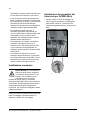
Mechanical installation
WARNING! If the drive is to be
connected to an IT power system
(i.e. ungrounded, or high-resistance-
grounded [over 30 ohms] power
system), the internal EMC filtering of
the drive must be disconnected. This should be
done before the drive is mechanically installed.
Refer to the Hardware Manual for detailed
instructions.
Fasten the drive module to the mounting base
using four screws through the four mounting
holes.
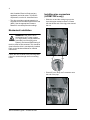
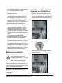
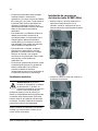
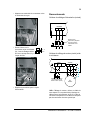
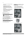
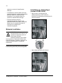
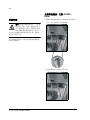
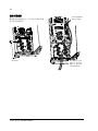
Installing pipe connectors
(ACSM1-04Lx only)
• Slide the nut and the cutting ring onto the
liquid inlet pipe marked coolant in. Ensure
that the thicker end of the ring points toward
the nut.
• Place the union body of the connector onto
the end of the pipe.

Quick installation guide - ACSM1-04/04Lx
5
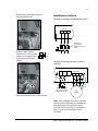
• Tighten the nut to the union
body, leaving 2…3 mm of
thread visible.
Overtightening may cause
leaking.
• Repeat the steps for the outlet pipe.
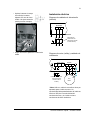
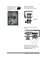
Electrical installation
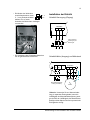
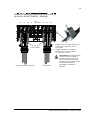
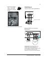
*Note: For motor cabling, use a separate
ground cable if the conductivity of the motor
cable shield is less than 50% of that of a phase
conductor and the cable has no symmetrical
ground conductors.
2…3
mm
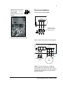
Supply (input) wiring diagram
INPUT
U1
L1 L2 L3
PE
PE
ACSM1-04/04Lx
V1 W1
Supply disconnecting
device (disconnecting
means) with fuses
OUTPUT
U1
V1
W1
3
~
Motor
UDC+
R+
UDC
-
R-
Optional braking
resistor (360° grounding
required)
ACSM1-04/04Lx
U2 V2 W2
PE
Motor (output) and resistor wiring diagram
*

Quick installation guide - ACSM1-04/04Lx
6
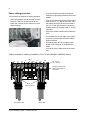
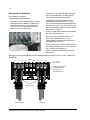
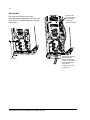
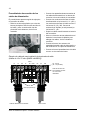
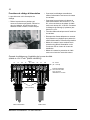
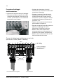
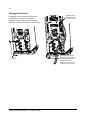
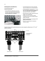
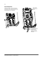
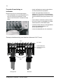
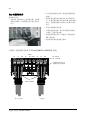
Power cabling procedure
The procedure is followed by cabling examples.
• Remove the plastic shroud covering the main
terminals. Remove the two screws at the
sides, then release the two clips on the front
edge as shown.
• Connect the twisted shields of the power
cables to the grounding terminals of the drive
module.
• Connect the phase conductors of the supply
cable to the U1, V1 and W1 terminals, and
the phase conductors of the motor cable to
the U2, V2 and W2 terminals. Connect the
braking resistor (if present) to the R– and R+
terminals.
• Secure the cables mechanically outside the
drive.
• Cut suitable slots on the edge of the plastic
shroud to accommodate the power cables.
Refit the shroud.
• Ground the other end of the supply cable
shield or PE conductor at the distribution
board.
• Ground the motor cable shield at the motor
end.
U1
V1
W1
U2
V2
W2R-
UDC+
R+
UDC-
Input power cable
Motor cable
Insulate the ends of the
cable lugs with tape or
shrink tube
30…44 N·m
(22…32 lbf·ft)
PE
8 N·m (5.9 lbf·ft)
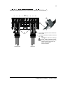
Cabling example for cable lug installation (16 to 70 mm2 [AWG6 to AWG2/0] cables)

Quick installation guide - ACSM1-04/04Lx
7
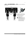
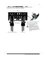
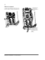
b
U1 V1 W1 U2 V2 W2R-
UDC+
R+ UDC-
Input power cable Motor cable
a. Connect the cable to the terminal. Tighten the
Allen screw to 20…40 N·m (15…30 lbf·ft).
b. Connect the terminal to the drive. Tighten to
30…44 N·m (22…32 lbf·ft).
WARNING! If the wire size is less than
95 mm
2
(3/0 AWG), a crimp lug must
be used. A cable of wire size less than
95 mm
2
(3/0 AWG) connected to this
terminal will loosen and may damage
the drive.
PE
8 N·m (5.9 lbf·ft)
Cabling example for screw terminal installation (95 to 240 mm
2
[AWG3/0 to 500MCM]
cables)
a

Quick installation guide - ACSM1-04/04Lx
8
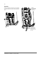
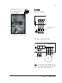
Control cabling
The drive comes with a clamp plate that can be
fastened at the top or the bottom of the JCU
Control Unit.
0.7 N·m
(6.2 lbf·in)
Use shrink tubing
or tape to contain
strands
Remove outer jacket
of cable at clamp to
expose cable shield.
Tighten to 1.5 N·m
(13 lbf·in)

Quick installation guide - ACSM1-04/04Lx
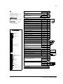
9
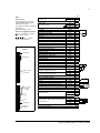
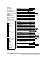
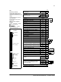
Notes:
[Default setting]
*Total maximum current: 200 mA
**Default assignment with ACSM1
Motion Control Program
The wiring shown is for demonstrative
purposes only.
For jumper settings, see text.
Wire sizes and tightening torques:
X2
: 0.5 … 2.5 mm
2
(24…12 AWG).
Torque: 0.5 N·m (5 lbf·in)
X3
, X4, X5, X6:
0.5 … 1.5 mm
2
(28…14 AWG).
Torque: 0.3 N·m (3 lbf·in)
X1
External power input
24 V DC, 1.6 A
+24VI 1
GND 2
X2
Relay output
250 V AC / 30 V DC
2 A
NO 1
COM 2
NC 3
X3
+24 V DC* +24VD 1
Digital I/O ground DGND 2
Digital input 1 [Stop/Start] DI1 3
Digital input 2 [EXT1/EXT2] DI2 4
+24 V DC* +24VD 5
Digital I/O ground DGND 6
Digital input 3 [Fault reset] DI3 7
Digital input 4 [Positioning start]** DI4 8
+24 V DC* +24VD 9
Digital I/O ground DGND 10
Digital input 5 [Position ref. set 1/2]** DI5 11
Digital input 6 [Homing start]** DI6 12
+24 V DC* +24VD 13
Digital I/O ground DGND 14
Digital input/output 1 [Ready] DIO1 15
Digital input/output 2 [Running] DIO2 16
+24 V DC* +24VD 17
Digital I/O ground DGND 18
Digital input/output 3 [Fault] DIO3 19
X4
Reference voltage (+) +VREF 1
Reference voltage (–) -VREF 2
Ground AGND 3
Analogue input 1 (Current or voltage, selectable
by jumper J1) [Speed reference]
AI1+ 4
AI1- 5
Analogue input 2 (Current or voltage, selectable
by jumper J2) [Torque reference]
AI2+ 6
AI2- 7
AI1 current/voltage selection J1
AI2 current/voltage selection J2
Thermistor input TH 8
Ground AGND 9
Analogue output 1 (current) [Output current] AO1 (I) 10
Analogue output 2 (voltage) [Actual speed] AO2 (U) 11
Ground AGND 12
X5
Drive-to-drive link termination J3
Drive-to-drive link.
B1
A2
BGND 3
X6
Safe Torque Off. Both circuits must be closed for
the drive to start.
OUT1 1
OUT2 2
IN1 3
IN2 4
Control panel connection X7
Memory unit connection X205
X3 (4 × 4-pole,
1 × 3-pole)
X2 (3-pole)
X1 (2-pole)
X4 (1 × 7-pole,
1 × 2-pole,
1 × 3-pole)
X5 (3-pole)
X6 (4-pole,
orange)
J1
J3
J2
Order of terminal headers and
jumpers
T

Quick installation guide - ACSM1-04/04Lx
10
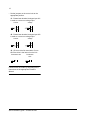
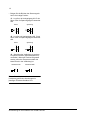
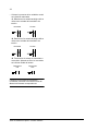
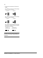
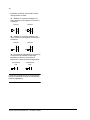
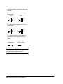
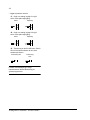
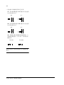
• Set the jumpers on the control unit to the
appropriate position:
J1 – Determines whether Analogue input AI1
is used as a current or voltage input.
J2 – Determines whether Analogue input AI2
is used as a current or voltage input.
J3 – Drive-to-drive link termination. Set to
ON if the drive is the last unit on the link.
Continue with drive start-up according to the
instructions in the appropriate Firmware
Manual.
AI1
AI2
8
7
AI1
AI2
8
7
Current Voltage
AI1
AI2
8
7
AI1
AI2
8
7
Current Voltage
T
Termination ON Termination
OFF
T

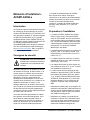
Kurzanleitung für die Installation des ACSM1-04/04Lx
11
Kurzanleitung
für die Installation des
ACSM1-04/04Lx
Einleitung
Diese Anleitung enthält die grundlegenden
Informationen über die mechanische und
elektrische Installation des ACSM1-04/04Lx
Frequenzumrichtermoduls (55 bis 160 kW). Die
vollständige Dokumentation finden Sie im
ACSM1-04 Frequenzumrichtermodule (55 bis
110 kW) Hardwarehandbuch (Code:
3AFE68912130 [Englisch] oder im ACSM1-
04Lx Liquid Cooled Drive Modules (55 to 160
kW) Hardware Manual (Code:
3AUA0000022083 [Englisch]) je nach Typ des
Frequenzumrichters. Beide sind im Internet
verfügbar unter www.abb.com/drives
); in dieser
Anleitung wird das Handbuch als das
Hardware-Handbuch bezeichnet.
Sicherheitshinweise
WARNUNG! Alle elektrischen Instal-
lations- und Wartungsarbeiten an
dem Antrieb dürfen nur von qualifi-
zierten Elektrikern durchgeführt wer-
den.
Arbeiten Sie niemals an dem Umrichter, der
Bremschopper-/widerstandskombination, dem
Motorkabel oder dem Motor bei eingeschalteter
Spannung. Nach dem Abschalten der
Spannungsversorgung warten Sie immer
5 Minuten, damit sich die Zwischenkreiskon-
densatoren entladen, bevor Sie damit
beginnen, an dem Frequenzumrichter, den
Steuerkabeln, dem Motor oder dem Motorkabel
zu arbeiten. Auch wenn der Umrichter nicht an
das speisende Netz angeschlossen ist, können
extern versorgte Steuerkreise gefährliche
Spannungen führen. Stellen Sie durch eine
Messung immer sicher, dass keine Spannung
anliegt.
Ein rotierender Permanentmagnet-Motor kann
gefährliche Spannung erzeugen. Sperren Sie
die Motorwelle mechanisch, bevor Sie einen
Permanentmagnet-Motor an den Antrieb
anschließen und bevor Sie irgendwelche Arbei-
ten an einem Umrichtersystem vornehmen, das
an einen Permanentmagnet-Motor angeschlos-
sen ist.
Achten Sie beim ACSM1-04Lx darauf, dass
durch das heiße Kühlmittel keine Personen ver-
brüht oder verletzt werden. Es dürfen keine
Arbeiten am Kühlsystem ausgeführt werden,
bis der Druck im Kühlsystem durch Stoppen
der Pumpen reduziert worden ist. Während des
Betriebs steht das heiße Kühlmittel im Kühl-
kreislauf unter hohem Druck (max. 1000 kPa,
55 °C [145 PSI, 131 °F]).
Planung der Installation
• Der ACSM1-04 ist ein IP20 (UL Open Type)
Antrieb zur Verwendung in beheizten
Innenräumen. Der Antrieb muss gemäß
Gehäuseklassifizierung in sauberer Luft
installiert werden. Die Kühlluft muss sauber,
frei von korrodierenden Materialien und
elektrisch leitendem Staub sein. Ausführliche
Spezifikationen finden Sie im
Hardwarehandbuch.
• Die maximale Umgebungslufttemperatur
beträgt 40 °C (104 °F) bei Nennstrom.
Der Strom ist für 41 bis 55 °C (104 bis
131 °F) zu reduzieren.
• Der Antrieb eignet sich für die Verwendung
in einem Netz mit einer Leistung von nicht
mehr als 100.000 A eff. Kurzschlussstrom,
maximal 480 V.
• Die Kabel innerhalb des Motorschaltkreises
müssen für mindestens 75 °C (167 °F) in UL-
kompatiblen Installationen klassifiziert sein.
• Installieren Sie ein handbetriebenes Ein-
gangstrennvorrichtung (Trennorgan) zwi-
schen der AC-Einspeisung und dem
Frequenzumrichter. Das Trennorgan muss
zu einem Typ gehören, der in offener Posi-

Kurzanleitung für die Installation des ACSM1-04/04Lx
12
tion verriegelt werden kann, damit Installati-
ons- und Wartungsarbeiten an dem
Frequenzumrichter oder dem Motor durchge-
führt werden können.
• Das Eingangskabel muss durch Sicherungen
oder Leitungsschutzautomaten geschützt
sein. Geeignete IEC- (Klasse gG) und UL-
(Klasse T) Sicherungen sind im Abschnitt
Technische Daten im Hardwarehandbuch
aufgeführt. Informationen zu geeigneten Lei-
stungsschutzautomaten erhalten Sie bei
Ihrer zuständigen ABB-Vertretung.
• Zur Installation in den Vereinigten Staaten
muss der Zweigstromkreisschutz mit dem
National Electrical Code (NEC) und allen
anwendbaren lokalen Richtlinien überein-
stimmen. Um diese Anforderung zu erfüllen,
verwenden Sie die UL-klassifizierten Siche-
rungen.
• Zur Installation in Kanada muss der
Zweigstromkreisschutz mit dem Canadian
Electrical Code und allen anwendbaren
Richtlinien der Provinzen übereinstimmen.
Um diese Anforderung zu erfüllen, verwen-
den Sie die UL-klassifizierten Sicherungen.
• Der Frequenzumrichter bietet einen Über-
lastungsschutz in Übereinstimmung mit dem
National Electrical Code (NEC). Im jeweili-
gen Programmier-Handbuch finden Sie die
Einstellungen zum Überlastungsschutz.
Mechanische Installation
WARNUNG! Wenn der Antrieb an
ein IT-Versorgungssystem ange-
schlossen werden soll (d.h. ein unge-
erdetes oder mit hohem Widerstand
[über 30 Ohm] geerdetes Versor-
gungssystem), muss die interne EMV-Filterung
des Frequenzumrichters abgetrennt werden.
Dies muss erfolgen, bevor der Antrieb mecha-
nisch installiert wird. Ausführliche Anweisungen
finden Sie im Hardware-Handbuch.
Befestigen Sie das Antriebsmodul mit vier
Schrauben durch die vier Montagelöcher am
Grundrahmen.
Installation der Kühlmittelrohr-
Verbinder (nur ACSM1-04Lx)
• Die Mutter und den Quetschring auf das
Kühlmitteleinlassrohr stecken, das mit
„coolant in“ (Kühlmittel Ein) gekennzeichnet
ist. Das dickere Ende des Rings muss zur
Mutter zeigen.
• Das Gegenstück der Verbindung auf das
Rohrende stecken.

Kurzanleitung für die Installation des ACSM1-04/04Lx
13
• Die Mutter des Verbinders
soweit festschrauben, dass
2…3 mm Gewinde sichtbar
bleiben. Ein zu festes
Anziehen der Mutter kann Leckagen
verursachen.
• Die Verbindung der Kühlmittelauslassrohre
auf die gleiche Weise vornehmen.
Installation der Elektrik
*Hinweis: Verwenden Sie zur Motorverkabe-
lung ein separates Erdungskabel, wenn die
Leitfähigkeit der Motorkabelabschirmung weni-
ger als 50% der Leitfähigkeit des Phasenleiters
beträgt und das Kabel nicht über symmetrische
Erdungsleiter verfügt.
2…3
mm
Schaltbild Versorgung (Eingang)
EINGANG
U1
L1 L2 L3
PE
PE
ACSM1-04/04Lx
V1 W1
Trennvorrichtung
(Trennorgan) mit
Sicherungen
AUSGANG
U1
V1
W1
3
~
Motor
UDC+
R+
UDC-
R-
Optionaler
Bremswiderstand (360°
Erdung erforderlich)
ACSM1-04/04Lx
U2 V2 W2
PE
Schaltbild Motor (Ausgang) und Widerstand
*

Kurzanleitung für die Installation des ACSM1-04/04Lx
14
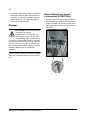
Anschluss der Netzkabel
Das Verfahren wird durch
Verkabelungsbeispiele illustriert.
• Entfernen Sie die Plastikabdeckung, welche
die Hauptklemmen abdeckt. Entfernen Sie
die beiden Schrauben an den Seiten und
lösen Sie dann wie abgebildet die beiden
Klammern an der Vorderkante.
• Verbinden Sie die gedrillten Abschirmungen
der Leistungskabel mit den Erdungsklem-
men des Frequenzumrichtermoduls.
• Verbinden Sie die Phasenleiter des Eins-
peisekabels mit den Klemmen U1, V1 und
W1, und die Phasenleiter des Motorkabels mit
den Klemmen U2, V2 und W2. Schließen Sie
den Bremswiderstand (falls vorhanden) an die
Klemmen R– und R+ an.
• Sichern Sie die Kabel mechanisch außerhalb
des Frequenzumrichters.
• Schneiden Sie passende Schlitze in den
Rand der Plastikabdeckung, um die
Leistungskabel aufzunehmen. Bringen Sie
die Abdeckung wieder an.
• Erden Sie das andere Ende der Abschirmung
des Einspeisekabels oder des PE-Leiters an
der Leistungsverteilungskarte.
• Erden Sie die Motorkabelabschirmung am
Motorende.
U1
V1
W1
U2
V2
W2R-
UDC+
R+
UDC-
Einspeisekabel
Motorkabel
Isolieren Sie die Enden
der Kabelschuhe mit
Isolierband oder
Schrumpfschlauch
30…44 Nm
(22…32 lbf·ft)
PE
8 Nm (5,9 lbf·ft)
Beispiel für den Schraubanschluss mit Kabelschuhen (für Kabel16 bis 70 mm
2
[AWG6 bis
AWG2/0] )

Kurzanleitung für die Installation des ACSM1-04/04Lx
15
b
U1 V1 W1 U2 V2 W2R-
UDC+
R+ UDC-
Einspeisekabel Motorkabel
a. Montieren Sie die Schraubklemmen an den
Kabelleitern. Ziehen Sie die Innensechskant-
schraube auf 20…40 Nm (15…30 lbf·ft) fest.
b. Schließen Sie die Klemmen an den
Frequenzumrichter an. Ziehen Sie mit
30…44 N·m (22…32 lbf·ft) fest.
WARNUNG! Wenn der
Leiterquerschnitt weniger als 95 mm
2
beträgt (3/0 AWG), muss eine Crimp-
Klemme verwendet werden. Ein Kabel
mit einem Leiterquerschnitt von
weniger als 95 mm
2
(3/0 AWG), das an
diese Klemme angeschlossen wird,
würde sich lösen und kann den
Frequenzumrichter beschädigen.
PE
8 Nm (5,9 lbf·ft)
Beispiel für den Kabelanschluss mit Schraubklemmen (Kabel 95 bis 240 mm
2
[AWG3/0 bis
500MCM] Kabel)
a

Kurzanleitung für die Installation des ACSM1-04/04Lx
16
Steuerkabel
Der Frequenzumrichter ist mit einem
Kabelabfangblech ausgestattet, das oben oder
unten an der JCU-Regelungseinheit befestigt
werden kann.
0,7 Nm
(6,2 lbf·in)
Verwenden Sie
Schrumpfschlauch
oder Isolierband,
um die Leiter
zusammenzuhalten
.
Entfernen Sie die äußere
Ummantelung des
Kabels im Bereich der
Schelle, um die Kabelab-
schirmung freizulegen.
Ziehen Sie die
Schrauben mit 1,5 Nm
(13 lbf·in) fest

Kurzanleitung für die Installation des ACSM1-04/04Lx
17
Bemerkungen:
[Standardeinstellungen]
*Maximalstrom, gesamt: 200 mA
**Standardzuweisung mit ACSM1
Motion Control Program
Gezeigte Anschlüsse dienen nur als
Beispiel.
Weitere Informationen zu den
Anschlüssen und Jumpern enthält der
folgende Text.
Kabelquerschnitte und
Anzugsmomente:
X2
: 0.5 … 2,5 mm
2
(24…12 AWG).
Anzugsmoment: 0,5 Nm (5 lbf·in)
X3
, X4, X5, X6:
0.5 … 1,5 mm
2
(28…14 AWG).
Anzugsmoment: 0,3 Nm (3lbf·ft)
X1
Externer Spannungsversorgungsanschluss
24 V DC, 1,6 A
+24VI 1
GND 2
X2
Relaisausgang
250 V AC / 30 V DC
2 A
NO 1
COM 2
NC 3
X3
+24 V DC* +24VD 1
Digitale-E/A-Masse DGND 2
Digitaleingang 1 DI1 3
Digitaleingang 2 DI2 4
+24 V DC* +24VD 5
Digitale-E/A-Masse DGND 6
Digitaleingang 3 DI3 7
Digitaleingang 4 DI4 8
+24 V DC* +24VD 9
Digitale-E/A-Masse DGND 10
Digitaleingang 5 DI5 11
Digitaleingang 6 DI6 12
+24 V DC* +24VD 13
Digitale-E/A-Masse DGND 14
Digitaleingang/-ausgang 1 DIO1 15
Digitaleingang/-ausgang 2 DIO2 16
+24 V DC* +24VD 17
Digitale-E/A-Masse DGND 18
Digitaleingang/-ausgang 3 DIO3 19
X4
Referenzspannung (+) +VREF 1
Referenzspannung (–) -VREF 2
Masse AGND 3
Analogeingang 1 (Strom oder Spannung mit
Jumper J1 einstellbar)
AI1+ 4
AI1- 5
Analogeingang 2 (Strom oder Spannung mit
Jumper J1 einstellbar)
AI2+ 6
AI2- 7
AI1 Auswahl Strom/Spannung J1
AI2 Auswahl Strom/Spannung J2
Thermistor-Eingang TH 8
Masse AGND 9
Analogausgang 1 (Strom) AO1 (I) 10
Analogausgang 2 (Spannung) AO2 (U) 11
Masse AGND 12
X5
Antrieb-Antrieb-Kommunikation, Abschluss J3
Antrieb-Antrieb-Kommunikation (Drive-to-Drive-
Link). Siehe separater Abschnitt unten.
B1
A2
BGND 3
X6
Sicher abgeschaltetes Moment. Beide
Stromkreise müssen zum Start des Antriebs
geschlossen sein. Siehe separater Abschnitt
unten.
OUT1 1
OUT2 2
IN1 3
IN2 4
Steuertafel-Anschluss X7
Memory-Unit-Anschluss X205
X3 (4 × 4-polig,
1 × 3-polig)
X2 (3-polig)
X1 (2-polig)
X4 (1 × 7-polig,
1 × 2-polig,
1 × 3-polig)
X5 (3-polig)
X6 (4-polig,
orange)
J1
J3
J2
Anordnung der Klemmen und
Jumper
T

Kurzanleitung für die Installation des ACSM1-04/04Lx
18
• Bringen Sie die Brücken der Steuerungsein-
heit in die richtige Position:
J1 – Legt fest, ob Analogeingang AI1 für ein
Strom- oder ein Spannungssignal verwendet
wird.
J2 – Legt fest, ob Analogeingang AI2 für ein
Strom- oder ein Spannungssignal verwendet
wird.
J3 – Abschluss der Verbindung zu anderen
Frequenzumrichtern (Antrieb-Antrieb-Kom-
munikation). Muss auf Position ON gestellt
werden, wenn der Frequenzumrichter die
letzte Einheit in der Verbindung ist.
Fahren Sie mit der Inbetriebnahme des
Umrichters gemäß den Anweisungen im
jeweiligen Firmware-Handbuch fort.
AI1
AI2
8
7
AI1
AI2
8
7
Strom Spannung
AI1
AI2
8
7
AI1
AI2
8
7
Strom Spannung
T
Abschluss ON Abschluss OFF
T

Guía de instalación rápida – ACSM1-04/04Lx
19
Guía de instalación rápida –
ACSM1-04/04Lx
Introducción
Esta guía contiene información muy básica
acerca de la instalación mecánica y eléctrica
del módulo de convertidor de frecuencia
ACSM1-04/04Lx (de 55 a 160 kW). Para
obtener una documentación completa, consulte
el Manual de hardware de los módulos de
convertidor de frecuencia ACSM1-04 (de 55 a
110 kW) (código: 3AFE68912130 [inglés]) o el
Manual de hardware de los módulos de
convertidor de potencia de refrigeración líquida
ACSM1-04Lx (de 55 a 160 kW) (código
3AUA0000022083, [inglés]) según el tipo de
convertidor. disponibles en www.abb.com/
drives. En esta guía de instalación rápida el
manual se denomina Manual de hardware.
Instrucciones de seguridad
¡ADVERTENCIA! Todos los trabajos
de instalación eléctrica y manten-
imiento realizados en el convertidor
deben ser realizados únicamente por
electricistas cualificados.
Nunca trabaje en el convertidor, el circuito del
chopper de frenado, el cable a motor o el motor
con la alimentación del convertidor conectada.
Tras desconectar la alimentación de entrada,
espere siempre 5 minutos a que se
descarguen los condensadores del circuito
intermedio antes de trabajar en el convertidor
de frecuencia, los cables de control, el motor o
el cable a motor. Los circuitos de control
alimentados de forma externa pueden conducir
tensión peligrosa incluso con la alimentación
de entrada del convertidor desconectada.
Realice siempre una medición para verificar
que no existe tensión.
Un motor de imanes permanentes en rotación
puede generar una tensión peligrosa. Bloquee
mecánicamente el eje del motor antes de
conectar un motor de imanes permanentes al
convertidor, así como antes de comenzar a
trabajar en un sistema de convertidor de
frecuencia conectado a un motor de imanes
permanentes.
Al trabajar con ACSM1-04Lx debe tener
cuidado con el refrigerante caliente. Detenga
las bombas para bajar la presión antes de
iniciar cualquier trabajo en el sistema de
refrigeración. En el circuito de refrigeración
hay refrigerante caliente a alta presión (máx.
1.000 kPa, 55ºC [145 PSI, 131ºF]) cuando éste
está en funcionamiento.
Planificación de la instalación
• El ACSM1-04/04Lx es un convertidor de
frecuencia con protección IP20 (UL tipo
abierto) que deberá emplearse en interiores
con calefacción que estén controlados. El
convertidor deberá ser instalado en una
atmósfera limpia de conformidad con la
clasificación del armario. El aire de
refrigeración deberá estar limpio, libre de
materiales corrosivos y polvo conductor de
electricidad. Consulte la especificación
detallada en el Manual de hardware.
• La temperatura ambiente máxima es de
40 °C (104 °F) a intensidad nominal. Se
produce derrateo a temperaturas de entre
41 y 55 °C (104 y 131 °F).
• El convertidor es apto para ser usado en
circuitos que no proporcionen más de
100.000 amperios eficaces simétricos, 480 V
como máximo.
• Los cables situados en el circuito del motor
deben tener una especificación mínima de
75 °C (167 °F) en instalaciones realizadas
conforme a la norma UL.
• Instale un dispositivo de desconexión de
entrada accionado manualmente (medio de
desconexión) entre una fuente de
alimentación de CA y el convertidor. El
dispositivo de desconexión debe ser de un
tipo que pueda bloquearse en la posición
abierta para los trabajos de instalación y
mantenimiento realizados en el convertidor o
en el motor.

Guía de instalación rápida – ACSM1-04/04Lx
20
• El cable de entrada debe estar protegido
mediante fusibles o interruptores
automáticos. Se incluye una lista de fusibles
IEC (clase gG) y UL (clase T) adecuados en
la sección Datos técnicos del Manual de
hardware. Póngase en contacto con su
representante de ABB local para informarse
sobre los interruptores automáticos
adecuados.
• Para instalación en los Estados Unidos, se
deberá proporcionar la protección de
circuitos derivados, de conformidad con el
Código Eléctrico Nacional de Estados
Unidos (NEC) y con cualquier normativa
local aplicable. Para cumplir este requisito,
utilice fusibles con clasificación UL.
• Para instalación en Canadá, se deberá
proporcionar la protección de circuitos
derivados, de conformidad con el Código
Eléctrico de Canadá y con cualquier
normativa provincial aplicable. Para cumplir
este requisito, utilice fusibles con
clasificación UL.
• El convertidor proporciona protección contra
la sobrecarga de acuerdo con el National
Electrical Code (NEC) de los EE.UU.
Consulte el Manual de firmware
correspondiente para conocer los ajustes de
la función de protección de sobrecarga.
Instalación mecánica
¡ADVERTENCIA! Si se prevé
conectar el convertidor a un sistema
de alimentación IT (es decir, un
sistema de alimentación sin conexión
a tierra o con una tierra de alta
resistencia [superior a los 30 ohmios]), el
filtrado de compatibilidad electromagnética del
convertidor debe desconectarse. Esto debe
hacerse antes de la instalación mecánica del
convertidor. Consulte el Manual de hardware
para obtener instrucciones detalladas.
Sujete el módulo de convertidor a la base de
montaje con cuatro tornillos a través de los
cuatro orificios de montaje.
Instalación de conectores
de tuberías (sólo ACSM1-04Lx)
• Deslice la tuerca y el anillo cortante en la
tubería de entrada de líquido con el
indicador coolant in. Asegúrese de que el
extremo más ancho del anillo está encarado
hacia la tuerca.
• Coloque el cuerpo de unión del conector en
el extremo de la tubería.
Seite wird geladen ...
Seite wird geladen ...
Seite wird geladen ...
Seite wird geladen ...
Seite wird geladen ...
Seite wird geladen ...
Seite wird geladen ...
Seite wird geladen ...
Seite wird geladen ...
Seite wird geladen ...
Seite wird geladen ...
Seite wird geladen ...
Seite wird geladen ...
Seite wird geladen ...
Seite wird geladen ...
Seite wird geladen ...
Seite wird geladen ...
Seite wird geladen ...
Seite wird geladen ...
Seite wird geladen ...
Seite wird geladen ...
Seite wird geladen ...
Seite wird geladen ...
Seite wird geladen ...
Seite wird geladen ...
Seite wird geladen ...
Seite wird geladen ...
Seite wird geladen ...
Seite wird geladen ...
Seite wird geladen ...
Seite wird geladen ...
Seite wird geladen ...
Seite wird geladen ...
Seite wird geladen ...
Seite wird geladen ...
Seite wird geladen ...
Seite wird geladen ...
Seite wird geladen ...
Seite wird geladen ...
Seite wird geladen ...
Seite wird geladen ...
Seite wird geladen ...
Seite wird geladen ...
Seite wird geladen ...
Seite wird geladen ...
Seite wird geladen ...
-
 1
1
-
 2
2
-
 3
3
-
 4
4
-
 5
5
-
 6
6
-
 7
7
-
 8
8
-
 9
9
-
 10
10
-
 11
11
-
 12
12
-
 13
13
-
 14
14
-
 15
15
-
 16
16
-
 17
17
-
 18
18
-
 19
19
-
 20
20
-
 21
21
-
 22
22
-
 23
23
-
 24
24
-
 25
25
-
 26
26
-
 27
27
-
 28
28
-
 29
29
-
 30
30
-
 31
31
-
 32
32
-
 33
33
-
 34
34
-
 35
35
-
 36
36
-
 37
37
-
 38
38
-
 39
39
-
 40
40
-
 41
41
-
 42
42
-
 43
43
-
 44
44
-
 45
45
-
 46
46
-
 47
47
-
 48
48
-
 49
49
-
 50
50
-
 51
51
-
 52
52
-
 53
53
-
 54
54
-
 55
55
-
 56
56
-
 57
57
-
 58
58
-
 59
59
-
 60
60
-
 61
61
-
 62
62
-
 63
63
-
 64
64
-
 65
65
-
 66
66


ABB ACSM1-04 Series Quick Installation Manual
- Typ
- Quick Installation Manual
- Dieses Handbuch eignet sich auch für
in anderen Sprachen
- English: ABB ACSM1-04 Series
- français: ABB ACSM1-04 Series
- español: ABB ACSM1-04 Series
- italiano: ABB ACSM1-04 Series
- svenska: ABB ACSM1-04 Series
- suomi: ABB ACSM1-04 Series
Verwandte Artikel
-
ABB ACS880-01-115A-2 Quick Installation Manual
-
-
-
-
ABB ACS580-04 Quick Installation Manual
-
-
-
-
ABB ACS850-04 series Quick Installation Manual
-