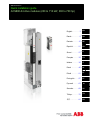
ABB ACS880-04 drive modules Quick Installation Manual
- Typ
- Quick Installation Manual

ABB industrial drives
Quick installation guide
ACS880-04 drive modules (200 to 710 kW, 300 to 700 hp)
English . . . . . . . 3
Dansk . . . . . . . . 9
Deutsch. . . . . . 15
Español. . . . . . 21
Suomi . . . . . . . 27
Français . . . . . 33
Italiano . . . . . . 39
Dutch . . . . . . . 45
Polski . . . . . . . 51
Português . . . . 57
. . . . . 63
Svenska . . . . . 69
Türkçe. . . . . . . 75
中文. . . . . . . . . 81
EN
DA
DE
ES
FI
FR
IT
NL
PL
PT
RU
SV
TR
ZH

List of related manuals
You can find manuals and other product documents in PDF format on the Internet. See section
Document library on the Internet on the inside of the back cover. For manuals not available in the
Document library, contact your local ABB representative.
The QR code below opens an online listing of the manuals applicable to this product.
Videos: http://fqrct.com/t/49004da and http://fqrct.com/t/a2081b9
Drive hardware manuals and guides Code (English)
Drive/Converter/Inverter safety instructions Multilingual code:
3AXD50000037978
ACS880-04 drive modules (200 to 710 kW, 300 to 700 hp)
hardware manual
3AUA0000128301
ACS880-04 drive modules (200 to 710 kW, 300 to 700 hp)
quick installation guide
3AXD50000009366
ACS-AP-x Assistant control panels user’s manual 3AUA0000085685
ACS880-01/04 +C132 marine type-approved drives
supplement
3AXD50000010521
Drive firmware manuals and guides
ACS880 primary control program firmware manual 3AUA0000085967
Quick start-up guide for ACS880 drives with primary
control program
3AUA0000098062
Option manuals and guides
DPMP-01 mounting platform for ACS-AP control panel
installation guide
3AUA0000100140
DPMP-02/03 mounting platform for control panels
installation guide
3AUA0000136205
FSO-12 safety functions module user’s manual 3AXD50000015612
FSO-21 safety functions module user’s manual 3AXD50000015614
ACS880 ATEX-certified Safe disconnection function
application guide
3AUA0000132231
ACS880-01 drives and ACS880-04 drive modules
common DC systems application guide
3AUA0000127818
FOCH du/dt filters hardware manual 3AFE68577519
Sine filters hardware manual 3AXD50000016814
Manuals and quick guides for I/O extension modules,
fieldbus adapters, etc.
ACS880-04 manuals
3AXD50000009366 Rev F
MUL
EFFECTIVE: 2017-02-22
2017 ABB Oy. All Rights Reserved.

EN – Quick installation guide 3
EN
DA
DE
ES
FI
FR
IT
PL
PT
RU
SV
TR
ZH
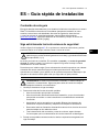
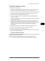
EN – Quick installation guide
Contents of this guide
This guide tells you briefly how to install the drive module into a 600 mm wide Rittal TS 8
cabinet. For installation examples in different cabinets and more detailed instructions,
engineering guide lines, technical data and complete safety instructions, see the hardware
manual (www.abb.com/drives
: Select Document Library and search for document number
3AUA0000128301 [English]).
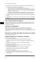
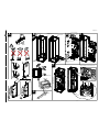
Obey the safety instructions
See figure A on page 87. If you ignore these instructions, injury or death, or damage to the
equipment can occur.
WARNING! Handle the drive module carefully. Open the support legs by pressing
each leg a little down and turning it aside (1, 2).
Do not tilt the drive module. It is heavy and its center of gravity is high. The
module will overturn from a sideways tilt of 5 degrees. Do not leave the module
unattended on a sloping floor.
To prevent the drive module from falling, attach its top lifting lugs with chains to the cabinet
frame before you push the module into the cabinet. Work carefully preferably with help
from another person. Keep a constant pressure with one foot on the base of the module to
prevent the module from falling on its back.
WARNING! If you are not a qualified electrician, do not do installation or
maintenance work. Go through these steps before you begin any installation or
maintenance work.
1. Clearly identify the work location.
2. Disconnect all possible voltage sources.
• Open the main disconnector of the drive.
• Open the disconnector of the supply transformer as the main disconnector of the
drive does not remove the voltage from the input busbars of the drive.
• Make sure that reconnection is not possible. Lock the disconnectors to open
position and attach a warning notice to them.
• Disconnect any external power sources from the control circuits before you do
work on the control cables.
• After you disconnect the drive, always wait for 5 minutes to let the intermediate
circuit capacitors discharge before you continue.
3. Protect any other energized parts in the work location against contact.
4. Take special precautions when close to bare conductors.

4 EN – Quick installation guide
EN
DA
DE
ES
FI
FR
IT
NL
PL
PT
RU
SV
TR
ZH
5. Measure that the installation is de-energized.
• Use a multimeter with an impedance of at least 1 Mohm.
• Make sure that the voltage between the drive module input power terminals
(L1/U1, L2/V1, L3/W1) and the grounding (PE) busbar is close to 0 V.
• Make sure that the voltage between the drive module UDC+ and UDC- terminals
and the grounding (PE) terminal is close to 0 V.
6. Install temporary grounding as required by the local regulations.
7. Ask for a permit to work from the person in control of the electrical installation work.
Select the power cables
Size the power cables according to local regulations to carry the nominal current given on
the type designation label of your drive.
Ensure the cooling
See table G on page 88 for the losses and the cooling air flow through the drive. The
allowed operating temperature range of the drive without derating is -15 to +40 °C.
Protect the drive and input power cables
See table G on page 88.
Install the drive module into a cabinet
See figure B on page 87:
• Install the punched section to the back of the cabinet frame.
• Remove the pedestal guide plate from the bottom of the drive module.
• Install the support rails and pedestal guide plate to the cabinet bottom frame.
• Install the telescopic insertion ramp to the pedestal guide plate.
See figure C on page 87:
• Remove the sheeting from the clear plastic shrouds from both sides.
See figure D on page 87:
• Install the bottom grille to the drive module if there is no bottom plate in the cabinet
and degree of protection of IP20 is needed for the drive module from the bottom side.
• Install the mounting bracket to the drive module.
• Install the top metallic shroud to the drive module.
• Install the back shrouds to the drive module.
See figure E on page 87:
• Attach the drive module to the cabinet frame with chains.
• Push the drive module into the cabinet along the telescopic insertion ramp.
• Remove the ramp.
See figure F on page 87:
• Attach the drive module to the pedestal guide plate.
• Attach the drive module from top to the punched section at the cabinet back. Note:
The mounting bracket grounds the drive module to the cabinet frame.

EN – Quick installation guide 5
EN
DA
DE
ES
FI
FR
IT
PL
PT
RU
SV
TR
ZH
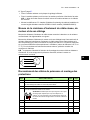
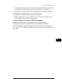
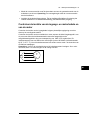
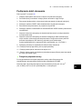
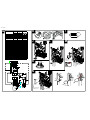
Check the insulation of the input and motor cables and
the motor
Check the insulation of the input cable according to local regulations before you connect it
to the drive.
See figure H on page 88. Ground the motor cable shield at the motor end. For minimal
interference, make a 360-degree grounding at the cable lead-through, or keep the pig tail
short.
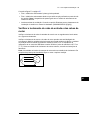
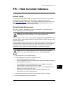
Check the insulation of the motor and motor cable when the motor cable is disconnected
from the drive, see figure I on page 88. Measure the insulation resistance between each
phase conductor and the Protective Earth conductor using a measuring voltage of
1000 V DC. The insulation resistance of an ABB motor must exceed 100 Mohm (reference
value at 25 °C or 77 °F). For the insulation resistance of other motors, consult the
manufacturer’s instructions. Note: Moisture inside the motor casing will reduce the
insulation resistance. If you suspect moisture, dry the motor and repeat the measurement.
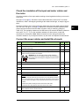
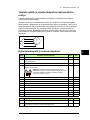
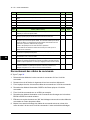
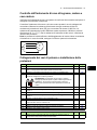
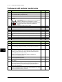
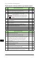
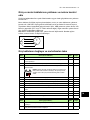
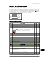
Connect the power cables and install the shrouds
Step Task (motor cables) Figure Page
1 Install the grounding terminal to the drive module base. J88
2 Run the motor cables to the cabinet. Ground the cable shields 360 degrees at
the cabinet lead-through
K88
3 Connect the twisted shields of the motor cables to the grounding terminal. L88
4 Screw in and tighten the insulators to the drive module by hand. Install the
T3/W2 connection terminal to the insulators.
WARNING! Do not use longer screws or bigger tightening
torque than given in the installation drawing. They can damage
the insulator and cause dangerous voltage to be present at the
module frame.
M88
5 Connect the phase T3/W2 conductors to the T3/W2 terminal. N88
6 Install the T2/V2 connection terminal to the insulators. See the warning in step
4.
- -
7 Connect the phase T2/V2 conductors to the T2/V2 connection terminal. - -
8 Install the T1/U2 connection terminal to the insulators. See the warning in step
4.
- -
9 Connect the phase T1/U2 conductors to the T1/U2 terminal. - -
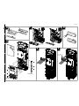
10 If there is no bottom plate in the cabinet and degree of protection of IP20 is
needed:
• Step drill carefully sufficiently big holes to the inner clear plastic shrouds for
the motor cables to the connected. Smooth the hole edges. Cut the shroud
from the holes to the edge to make it possible to put the shroud around the
cables.
• Remove the plastic sheeting from the shrouds from both sides.
O89
• Install the inner clear plastic shrouds around the motor cables. P89
11 Remove the plastic sheeting from the outer clear plastic shroud from both
sides. Install the shroud to the drive module.
Q89
12 Install the lower front cover to the drive module. Q89

6 EN – Quick installation guide
EN
DA
DE
ES
FI
FR
IT
NL
PL
PT
RU
SV
TR
ZH
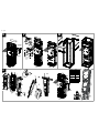
Install the air baffles
See figure W on page 90 and Guidelines for planning the cabinet installation in the
hardware manual.
Connect the control cables
See figure X on page 90.
1. Disconnect the control panel cable from connector X13 on the control unit.
2. Loosen the mounting screws of the control panel holder and take the holder off.
3. Install the control cable grounding clamp plate to the control unit.
4. Connect the power supply, BGDR and fiber optic cables to the control unit.
5. Attach the control unit, for example, to a DIN rail.
6. Connect the power supply and BGDR cables to the drive module BPOW and BGDR
terminals. Drive modules with SOIA terminals:
Connect the fiber optic cables to the
SOIA terminals.
7. Ground the outer shields of all external control cables 360 degrees at the cabinet lead-
through.
8. Ground the pair-cable shields of external control cables to a grounding clamp below
the control unit. Leave the other end of the shields unconnected or ground them
indirectly via a high-frequency capacitor with a few nanofarads, eg, 3.3 nF / 630 V.
9. Connect the conductors to the appropriate terminals of the control unit.
10. Wire the optional modules if included in the delivery.
11. Connect the control panel cable to connector X13.
12. Put the control panel holder on the control unit. Put the control panel to the recess if
removed.
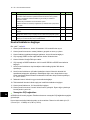
Step Task (input cables) Figure Page
1 Ground the input cable shields (if present) 360 degrees at the cabinet lead-
through.
- -
2 Connect the twisted shields of the input cables and separate ground cable (if
present) to the cabinet grounding busbar.
- -
3 Step drill carefully sufficiently big holes to the lead-through clear plastic shroud
for the cables to the connected. Align the holes in the vertical direction
according to the alignment holes in the shroud. Smooth the hole edges.
Remove the plastic sheeting from both sides of the shroud.
Attach the cables firmly to the cabinet frame to prevent chafing against the
hole edges.
R89
4 Put the conductors of the input cables through the drilled holes in the clear
plastic shroud.
S89
5 Connect the input power cable conductors to the L1/U1, L2/V1 and L3/W1
connection busbars.
T89
6 Move the lead-through clear plastic shroud along input cables to its final
position. Install the front clear plastic shroud and upper front cover. Remove
the cardboard protective covering from the drive module air outlet.
U90
7 Cut the hole for the lead-through clear plastic shroud in the side clear plastic
shroud. Install the side and top clear plastic shrouds to the drive module.
V90

EN – Quick installation guide 7
EN
DA
DE
ES
FI
FR
IT
PL
PT
RU
SV
TR
ZH
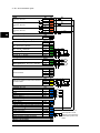
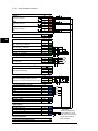
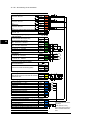
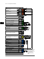
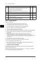
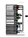
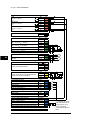
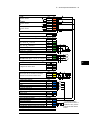
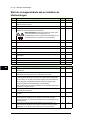
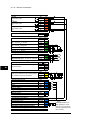
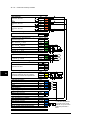
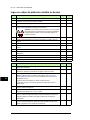
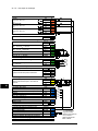
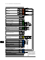
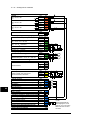
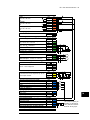
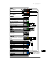
Default I/O connections
The default I/O connections of the Factory macro of the ACS880 primary control program
are shown below.
Wire sizes and tightening torques of the control board terminals: 0.5 … 2.5 mm
2
(24…12 AWG) and 0.5 N·m (5 lbf·in) for both stranded and solid wiring.

8 EN – Quick installation guide
EN
DA
DE
ES
FI
FR
IT
NL
PL
PT
RU
SV
TR
ZH
Relay outputs XRO1…XRO3
Ready
250 V AC / 30 V DC
2 A
NO
13
COM
12
NC
11
Running
250 V AC / 30 V DC
2 A
NO
23
COM
22
NC
21
Faulted(-1)
250 V AC / 30 V DC
2 A
NO
33
COM
32
NC
31
External power input XPOW
24 V DC, 2 A
GND
2
+24VI
1
Reference voltage and analog inputs J1, J2, XAI
AI1/AI2 current/voltage selection
AI1: U AI2: U
AI1: I AI2: I
By default not in use.
0(4)…20 mA, R
in
= 100 ohm
AI2-
7
AI2+
6
Speed reference
0(2)…10 V, R
in
> 200 kohm
AI1-
5
AI1+
4
Ground AGND
3
-10 V DC, R
L
1…10 kohm -VREF 2
10 V DC, R
L
1…10 kohm +VREF 1
Analog outputs XAO
Motor current 0…20 mA, R
L
< 500 ohm
AGND
4
AO2
3
Motor speed rpm 0…20 mA, R
L
< 500 ohm
AGND
2
AO1
1
Drive-to-drive link
J3, XD2D
Drive-to-drive link termination ON OFF
Drive-to-drive link
Shield
4
BGND
3
A
2
B
1
Safe torque off XSTO
Safe torque off. Both circuits must be closed for
the drive to start.
IN2
4
IN1
3
SGND
2
OUT
1
Digital inputs XDI
By default not in use. DI6
6
Constant speed 1 select (1 = on) DI5
5
Acceleration & deceleration select DI4
4
Reset DI3
3
Forward (0) / Reverse (1) DI2
2
Stop (0) / Start (1) DI1
1
Digital input/outputs XDIO
Output: Running DIO2
2
Output: Ready DIO1
1
Ground selection J6
Auxiliary voltage output, digital input interlock XD24
Digital input/output ground DIOGND
5
+24 V DC 200 mA
1)
+24VD 4
Digital input ground DICOM
3
+24 V DC 200 mA
1)
+24VD 2
Run enable
DIIL
1
Safety functions module connection X12
Control panel connection X13
Memory unit connection X205
Fault
1)
Total load capacity of
these outputs is 4.8 W
(200 mA / 24 V) minus the
power taken by DIO1 and
DIO2.

DA – Hurtig installationsvejledning 9
EN
DA
ES
FI
FR
IT
NL
PL
PT
RU
SV
TR
ZH
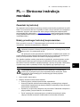
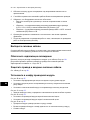
DA – Hurtig
installationsvejledning
Indholdet i denne vejledning
Denne vejledning giver dig en kortfattet vejledning til, hvordan du kan installere
frekvensomformermodulet i et 600 mm bredt Rittal TS 8-kabinet. Hvis du vil se
installationseksempler for andre kabinetter og få mere detaljerede instruktioner, tekniske
retningslinjer, tekniske data og komplette sikkerhedsinstruktioner, kan du se
hardwaremanualen (www.abb.com/drives:
Vælg Document Library, og søg efter
dokumentnummer 3AUA0000128301 [på engelsk]).
Overhold sikkerhedsinstruktionerne
Se figur A på side 87. Hvis disse instruktioner ignoreres, kan det resultere i personskader,
dødsfald eller skade på udstyret.
ADVARSEL! Håndter frekvensomformermodulet forsigtigt. Åbn støttebenene ved
at trykke lidt ned på hvert ben og dreje det til side (1, 2).
Frekvensomformermodulet må ikke vippes. Det er tungt og har et højt
tyngdepunkt. Enheden vil vælte, hvis den udsættes for en sidelæns hældning på 5
grader. Efterlad ikke modulet uovervåget på et gulv, der hælder.
For at forhindre frekvensomformermodulet i at vælte, skal du fastgøre de øverste løfteøjer
med kæder til kabinetrammen, inden du skubber modulet ind i kabinettet. Vær forsigtig,
når du udfører arbejdet, gerne med hjælp fra en anden person. Hold et konstant tryk med
én fod på modulets fod for at forhindre modulet i at falde bagover.
ADVARSEL! Installations- eller vedligeholdelsesarbejde må kun udføres af
uddannede elektrikere. Følg disse trin, inden installations- eller
vedligeholdelsesarbejde påbegyndes.
1. Identificer arbejdsstedet tydeligt.
2. Frakobl alle strømkilder.
• Åbn frekvensomformerens hovedafbryder.
• Hvis afbryderen til forsyningstransformeren åbnes som hovedafbryder til
frekvensomformeren, er der stadig strøm i frekvensomformerens
indgangseffektskinner.
• Sørg for, at gentilkobling ikke er mulig. Lås afbryderne i åben position, og fastgør
en advarsel til dem.
• Frakobl eventuelle eksterne strømkilder fra styrekredsene, inden der udføres
arbejde på styrekablerne.
• Efter at strømmen til frekvensomformeren er afbrudt, skal du altid vente i 5
minutter på, at kondensatorerne i mellemkredsen aflades, inden du fortsætter
3. Beskyt eventuelle andre strømførende dele i arbejdsområdet mod kontakt.
4. Tag særlige forholdsregler, når der arbejdes i nærheden af ikke-isolerede ledere.

10 DA – Hurtig installationsvejledning
EN
DA
DE
ES
FI
FR
IT
NL
PL
PT
RU
SV
TR
ZH
5. Kontroller, at installationen ikke er strømførende.
• Brug et multimeter med en impedans på mindst 1 Mohm.
• Sørg for, at spændingen mellem frekvensomformermodulets indgangs-
effektterminaler (L1/U1, L2/V1, L3/W1) og jordskinnen (PE) er tæt på 0 V.
• Sørg for, at spændingen mellem frekvensomformermodulets terminaler UDC+ og
UDC- og jordskinnen (PE) er tæt på 0 V.
6. Installer midlertidig jordforbindelse som påkrævet i henhold til lokale bestemmelser.
7. Bed om tilladelse til at arbejde fra den person, der er ansvarlig for det elektriske
installationsarbejde.
Vælg effektkabler
Vælg en størrelse til kablerne i henhold til lokale forskrifter til at bære den nominelle strøm,
der er anført på mærket med typebetegnelsen på din frekvensomformer.
Sørg for kølingen
Se tabel G på side 88 for tabene og frekvensomformeren gennemstrømning af kølende
luft. Frekvensomformerens tilladte driftstemperaturområde uden reduktion er -15 til +40
°C.
Beskyt frekvensomformeren og netkabler
Se tabel G på side 88.
Installer frekvensomformermodulet i et kabinet.
Se figur B på side 87:
• Monter den hullede sektion bagerst på kabinetrammen.
• Monter styreskinner og soklens styreplade til kabinettets bundramme.
• Monter den teleskopiske rampe til indsættelse på soklens styreplade.
Se figur C på side 87:
• Fjern beskyttelsen fra de gennemsigtige plastikafdækninger på begge sider.
Se figur D på side 87:
• Monter metaltopafdækning på frekvensomformermodulet.
• Monter bagsideafdækning på frekvensomformermodulet.
Se figur E på side 87:
• Fastgør frekvensomformermodulet til kabinetrammen med kæder.
• Skub frekvensomformermodulet ind i kabinettet langs den teleskopiske rampe.
• Fjern rampen.

DA – Hurtig installationsvejledning 11
EN
DA
ES
FI
FR
IT
NL
PL
PT
RU
SV
TR
ZH
Se figur F på side 87:
• Fastgør frekvensomformermodulet til soklens styreplade.
• Fastgør frekvensomformermodulet fra top til den hullede sektion på kabinetbagsiden.
Bemærk! Monteringsbeslaget fastgør frekvensomformermodulet til kabinettets
ramme.
• Monter luftpladerne. Se kapitlet Guidelines for planning the cabinet installation i
hardwaremanualen (3AUA0000128301 [på engelsk]).
Kontroller isoleringen på input- og motorkabler samt
motoren
Kontrollér isoleringen af indgangskablet i overensstemmelse med de nationale forskrifter,
inden du tilslutter det til frekvensomformeren.
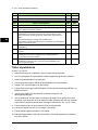
Kontroller isoleringen af motor og motorkabel, når motorkablet er koblet fra
frekvensomformeren. Mål isolationsmodstanden mellem hver faseleder og
beskyttelsesjordens leder med en målespænding på 1000 V DC. Isolationsmodstanden på
en ABB-motor skal være større end 100 Mohm (referenceværdi ved 25 °C eller 77 °F).
Oplysninger om isolationsmodstanden på andre motorer kan findes i producentens
vejledninger.
Bemærk! Fugt inden i motorhuset reducerer isolationsmodstanden. Hvis du har mistanke
om at der findes fugt, skal motoren tørres, og målingen gentages.
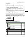
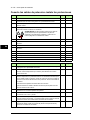
Tilslut netkabler og monter afdækningerne
Trin Opgaver (motorkabler) Figur Side
1 Monter jordterminalen på frekvensomformermodulets fod. H 88
2 Træk motorkablerne til kabinettet Jord kabelskærmen 360 gader ved
kabelindgangen
I 88
3 Forbind de snoede dele af motorkabelskærmene med jordterminalen. J 88
4 Skru og spænd med hånden isolationen på frekvensomformermodulet. Monter
T3/W2-tilslutningsterminalen i isolationen.
ADVARSEL! Undgå at bruge længere skruer eller større
tilspændingsmoment end angivet i monteringstegningen. De
kan ødelægge isolationen og forårsage at der findes farlig
spænding i modulrammen.
K 88
5 Tilslut T3/W2-faselederne til T3/W2-terminalen. L 88
6 Monter T2/V2-tilslutningsterminalen i isolationen. Se advarslen i trin 4. - -
7 Tilslut T2/V2-faselederne til T2/V2-tilslutningsterminalen. - -
8 Monter T1/U2-tilslutningsterminalen i isolationen. Se advarslen i trin 4. - -
9 Tilslut T1/U2-faselederne til T1/U2-terminalen. - -
10 Fjern plastikbeskyttelsen fra de gennemsigtige plastikafdækninger på begge
sider.
M 89
11 Monter afdækningen på frekvensomformermodulet. M 89
ohm
M
3~
U1
V1
W1
PE

12 DA – Hurtig installationsvejledning
EN
DA
DE
ES
FI
FR
IT
NL
PL
PT
RU
SV
TR
ZH
Tilslut styrekablerne
Se figur T på side 90.
1. Afbryd tilslutningen af styrekablerne fra X13-stikket på styreenheden.
2. Løsn monteringsskruerne på holderen til betjeningspanelet og afmonter holderen.
3. Installer styrekabelbøjlen til styreenheden.
4. Forbind strømforsyningen, BGDR og fiberoptikkabler med styreenheden.
5. Fastgør f.eks. styreenheden på en DIN-skinne.
6. Forbind strømforsyningen og BGDR-kabler til frekvensomformermodulets BPOW- og
BGDR-terminaler.
7. Jord de ydre skærme for alle eksterne styrekabler 360 gader ved
kabinetgennemføringen.
8. Jord de skærmede, snoede kabler for eksterne styrekabler til en jordklemme under
styrekortet. Lad den anden ende af skærmene være frakoblet, eller slut dem indirekte
til jord med en højfrekvenskondensator på nogle få nanofarad (f.eks. 3,3 nF / 630V).
9. Forbind kablets ledere til de korrekte klemmer på styreenheden.
10. Forbind de valgfrie moduler, hvis de indgår i leverancen.
11. Forbind betjeningspanelets kabel til X13-stikket.
12. Sæt betjeningspanelets holder på styreenheden. Sæt betjeningspanelet i indhakket,
hvis det er fjernet.
12 Monter nederste frontafdækning på frekvensomformermodulet. M 89
13 Tilslut motorkablet i motorenden. N 89
Trin Opgaver (indgangskabler) Figur Side
1 Jord indgangskabelskærmene (hvis de findes) 360 gader ved kabelindgangen - -
2 Forbind de snoede dele af indgangskablerne og de separate jordingskabler
(hvis de findes) til kabinettets jordskinne.
- -
3 Bor trinvist og forsigtigt huller af passende størrelse gennem den klare
plastikafdækning hvor kablerne skal forbindes. Hullerne justeres i lodret
retning så de passer til justeringshullerne i afdækningen. Udglat hullernes
kanter.
Fjern plastikbeskyttelsen på begge sider af afdækningen.
Fastgør kablerne sikkert til kabinetrammen for at forhindre, at de ødelægges af
gnidning mod hullernes kanter.
O 89
4 Træk lederne for indgangskablerne gennem de borede huller i den klare
plastafdækning.
P 89
5 Forbind netkablernes indgangsledere til forbindelsesskinnerne L1/U1, L2/V1
og L3/W1.
Q 89
6 Monter den klare plastikafdækning til gennemføring. Monter frontens klare
plastikafdækning og øverste frontdæksel. Fjern papbeskyttelsen fra
frekvensomformermodulets luftudtag.
R 90
7 Skær hullet til den klare plastikafdækning til gennemføring i sidens klare
plastikafdækning. Monter sidens og toppens klare plastikafdækning på
frekvensomformermodulet.
S 90
Trin Opgaver (motorkabler) Figur Side

DA – Hurtig installationsvejledning 13
EN
DA
ES
FI
FR
IT
NL
PL
PT
RU
SV
TR
ZH
I/O-standardtilslutninger
I/O-standardtilslutninger til fabriksmakroen for det primære styreprogram for ACS880 er
vist herunder.
Ledningsstørrelser og fastspændingsmomenter for styrekortets terminaler: 0,5 … 2,5 mm
2
(24 … 12 AWG) og 0,5 N·m (5 lbf·in) til både trådledere og massive ledere.

14 DA – Hurtig installationsvejledning
EN
DA
DE
ES
FI
FR
IT
NL
PL
PT
RU
SV
TR
ZH
Relæudgang XRO1-XRO3
Startklar
250 V AC / 30 V DC
2 A
NEJ
13
COM
12
NC
11
Kører
250 V AC / 30 V DC
2 A
NEJ
23
COM
22
NC
21
Fejl(-1)
250 V AC / 30 V DC
2 A
NEJ
33
COM
32
NC
31
Ekstern effektindgang XPOW
24 V DC, 2 A
GND
2
+24VI
1
Referencespænding og analoge indgange J1, J2, XAI
AI1/AI2 til valg af strøm/spænding
AI1: U AI2: U
AI1: I AI2: I
Som standardindstilling ubenyttet.
0(4)…20 mA, R
in
= 100 ohm
AI2-
7
AI2+
6
Hastighedsreference
0(2)…10 V, R
in
> 200 kohm
AI1- 5
AI1+
4
Jord AGND
3
-10 V DC, R
L
1-10 kohm -VREF 2
10 V DC, R
L
1-10 kohm +VREF 1
Analoge udgange XAO
Motorstrøm 0-20 mA, R
L
< 500 ohm
AGND
4
AO2
3
Motorhastighed o/min 0-20 mA,
R
L
< 500 ohm
AGND
2
AO1
1
Drev-til-drev-forbindelse J3, XD2D
Afbryder til drev-til-drev-forbindelse
3)
TIL FRA
Drev-til-drev-forbindelse
Skærm
4
BGND
3
A
2
B
1
Safe torque off XSTO
Safe torque off. Begge kredse skal være
lukkede, for at frekvensomformeren kan starte.
IN2
4
IN1
3
SGND
2
OUT
1
Digitale indgange XDI
Som standardindstilling ubenyttet. DI6
6
Valg af konstant hastighed 1 (1 = til) DI5
5
Acceleration og deceleration vælg DI4
4
Nulstil DI3
3
Forlæns (0) / Baglæns (1) DI2
2
Stop (0) / Start (1) DI1
1
Digitale indgange/udgange XDIO
Udgang: Kører DIO2
2
Udgang: Startklar DIO1
1
Valg af jord J6
Ekstra spændingsudgang, interlock for
digital indgang
XD24
Jording af digital indgang/udgang DIOGND
5
+24 V DC 200 mA
1)
+24VD 4
Jording af digital indgang DICOM
3
+24 V DC 200 mA
1)
+24VD 2
Start frigiv DIIL
1
Modulforbindelse med
sikkerhedsfunktioner
X12
Tilslutning til betjeningspanel X13
Tilslutning til hukommelsesenhed X205
Fejl
1)
Den totale
belastningskapacitet for
disse udgange er 4,8 W
(200 mA / 24 V) minus den
strøm, der benyttes af
DIO1 og DIO2.

DE – Kurzanleitung für die Installation 15
DE
DA
ES
FI
FR
IT
PL
PT
RU
SV
TR
ZH
DE – Kurzanleitung für die
Installation
Inhalt dieser Anleitung
Diese Anleitung beschreibt in Kurzform die Installation und den Einbau des Frequenz-
umrichtermoduls in einen 600 mm breiten Rittal TS 8 Schaltschrank. Installationsbeispiele
für verschiedene Schaltschränke und detailliertere Anweisungen, Hinweise für die Pla-
nung, die technischen Daten und die kompletten Sicherheitsvorschriften enthält das Hard-
ware-Handbuch (www.abb.com/drives
: Wählen Sie Document Library und suchen Sie das
Dokument mit der Nummer 3AUA0000128301 [Englisch]).
Befolgen Sie die Sicherheitsvorschriften
Siehe Abbildung A auf Seite 87. Wenn die Sicherheitsvorschriften nicht befolgt werden,
können Verletzungen, tödliche Unfälle oder Schäden an den Geräten auftreten.
WARNUNG! Behandeln und bewegen Sie das Frequenzumrichtermodul vorsich-
tig. Klappen Sie die Stützwinkel aus, indem Sie sie etwas nach unten drücken und
zur Seite drehen (1, 2).
Das Frequenzumrichtermodul darf nicht gekippt werden. Es ist schwer und hat einen hoch
liegenden Schwerpunkt. Das Modul fällt ab einem Kippwinkel von 5 Grad zur Seite um.
Lassen Sie das Modul auf einem Boden mit Gefälle nicht unbeaufsichtigt stehen.
Um das Frequenzumrichtermodul gegen Umfallen zu sichern, befestigen Sie es an den
oberen Hebeösen mit Ketten am Schaltschrank bevor Sie es in den Schaltschrank schie-
ben. Arbeiten Sie dabei vorsichtig am besten mit Hilfe einer zweiten Person. Drücken Sie
außerdem mit einem Fuß konstant gegen den Sockel des Moduls, um zu verhindern, dass
es nach hinten umfällt.
WARNUNG! Installation und Wartung des Frequenzumrichters dürfen nur von
qualifiziertem Fachpersonal durchgeführt werden. Gehen Sie in folgenden Schrit-
ten vor, bevor Sie mit den Installations- und Wartungsarbeiten beginnen.
1. Eindeutige Bestimmung des Arbeitsortes.
2. Trennen Sie den Frequenzumrichter von allen Spannungsquellen, die möglich sind.
• Öffnen Sie das Hauptschütz des Frequenzumrichters.
• Öffnen Sie den Trennschalter des Einspeisetransformators, da der Haupttrenn-
schalter des Frequenzumrichters die Eingangstromschienen nicht spannungsfrei
schaltet.
• Stellen Sie sicher, dass ein erneutes Herstellen der Spannungsversorgung nicht
möglich ist. Die Trenneinrichtungen in Position geöffnet verriegeln und ein Warn-
schild daran anbringen.
• Trennen Sie alle externen Spannungsquellen von den Steuerungs-Stromkreisen
bevor Sie an den Steuerkabeln arbeiten.

16 DE – Kurzanleitung für die Installation
DE
DA
ES
FI
FR
IT
NL
PL
PT
RU
SV
TR
ZH
• Warten Sie nach dem Trennen des Frequenzumrichters von der Spannungs-
versorgung stets 5 Minuten, bis die Zwischenkreiskondensatoren entladen sind,
bevor Sie die Arbeiten fortsetzen.
3. Sichern Sie alle anderen unter Spannung stehenden Teile am Arbeitsort gegen Berüh-
rung.
4. Besondere Vorsichtsmaßnahmen sind in der Nähe von blanken Leitern erforderlich.
5. Stellen Sie durch Messungen sicher, dass die gesamte Installation spannungsfrei ist.
• Benutzen Sie dazu ein Multimessgerät mit einer Impedanz von mindestens
1 MOhm.
• Stellen Sie sicher, dass die Spannung zwischen den Einspeiseanschlüssen des
Frequenzumrichtermoduls (L1/U1, L2/V1, L3/W1) und der Erdungsschiene (PE)
annähernd 0 V beträgt.
• Stellen Sie sicher, dass die Spannung zwischen den UDC+ und UDC- Klemmen
des Frequenzumrichtermoduls und der Erdungsschiene (PE) annähernd 0 V
beträgt.
6. Installieren Sie für die Dauer der Arbeiten eine Erdung, die nach den örtlichen Vor-
schriften erforderlich ist.
7. Holen Sie die Arbeitsfreigabe von der Person ein, die die Aufsicht über die elektri-
schen Installationsarbeiten führt.
Auswahl der Leistungskabel
Die Leistungskabel müssen nach den örtlichen Vorschriften für den auf dem Typenschild
des Frequenzumrichters angegebenen Nennstrom ausreichend bemessen sein.
Ausreichende Kühlung sicherstellen
Siehe Tabelle G auf Seite 88, die Angaben zu den Verlustleistungen und dem erforderli-
chen Kühlluftstrom durch den Frequenzumrichter enthält. Der zulässige Umgebungs-tem-
peraturbereich für den Betrieb des Frequenzumrichters ohne Leistungsminderung ist
-15 bis +40 °C.
Schutz des Frequenzumrichters und der Einspeisekabel
Siehe Tabelle G auf Seite 88.
Einbau des Frequenzumrichtermoduls in einen Schalt-
schrank
Siehe Abbildung B auf Seite 87:
• Installieren Sie das vorgestanzte Blechprofil an der Rückseite des Schrankrahmens.
• Installieren Sie die Tragschienen und das Sockel-Führungsblech am Bodenrahmen
des Schranks.
• Installieren Sie die Teleskop-Moduleinfahrrampe am Sockel-Führungsblech.
Siehe Abbildung C auf Seite 87:
• Entfernen Sie die Schutzfolie der durchsichtigen Kunststoffabdeckungen auf beiden
Seiten.

DE – Kurzanleitung für die Installation 17
DE
DA
ES
FI
FR
IT
PL
PT
RU
SV
TR
ZH
Siehe Abbildung D auf Seite 87:
• Installieren Sie die obere Metallabdeckung am Frequenzumrichtermodul.
• Installieren Sie die hinteren Abdeckungen am Frequenzumrichtermodul.
Siehe Abbildung E auf Seite 87:
• Befestigen Sie das Frequenzumrichtermodul mit Ketten am Schaltschrankgehäuse.
• Schieben Sie das Frequenzumrichtermodul über die Teleskop-Einfahrrampe in den
Schaltschrank.
• Demontieren Sie die Rampe.
Siehe Abbildung F auf Seite 87:
• Befestigen Sie das Frequenzumrichtermodul am Sockel-Führungsblech.
• Befestigen Sie das Frequenzumrichtermodul von oben am vorgestanzten Blechprofil
an der Schrankrückseite. Hinweis: Mit dem Befestigungswinkel wird das Frequenz-
umrichtermodul über den Schrankrahmen geerdet.
• Montieren Sie die Luftleitbleche. Siehe Kapitel Guidelines for planning the cabinet
installation im Hardware-Handbuch (3AUA0000128301 [English]).
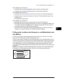
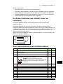
Prüfung der Isolation der Einspeise- und Motorkabel und
des Motors
Prüfen Sie die Isolation des Einspeisekabels auf Einhaltung der örtlichen Vorschriften
bevor es an den Frequenzumrichter angeschlossen wird.
Prüfen Sie die Isolation des Motors und des Motorkabels, wenn das Motorkabel vom Fre-
quenzumrichter getrennt ist. Messen Sie die Isolationswiderstände zwischen jeder Phase
und der Schutzerde mit einer Messspannung von 1000 V DC. Der Isolationswiderstand
eines ABB-Motors muss mehr als 100 MOhm betragen (Referenzwert bei 25 °C bzw.
77 °F). Die Isolationswiderstände anderer Motoren entnehmen Sie bitte der Anleitung des
Herstellers.
Hinweis: Feuchtigkeit innerhalb des Motorgehäuses reduziert den Isolationswiderstand.
Bei Verdacht auf Feuchtigkeit den Motor trocknen und die Messung wiederholen.
Ohm
M
3~
U1
V1
W1
PE

18 DE – Kurzanleitung für die Installation
DE
DA
ES
FI
FR
IT
NL
PL
PT
RU
SV
TR
ZH
Anschluss der Leistungskabel und Montage der Abdec-
kungen
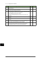
Schritt Aufgabe (Motorkabel) Bild Seite
1 Die Erdungsanschlüsse unten am Frequenzumrichtermodul installieren. H 88
2 Die Motorkabel in den Schrank führen. Die Kabelschirme mit einer 360-Grad-
Erdung an den Schrank-Kabeldurchführungen erden.
I 88
3 Die verdrillten Schirme der Motorkabel an den Erdungsanschluss anschließen. J 88
4 Die Isolatoren mit der Hand an das Frequenzumrichtermodul schrauben und
festziehen. Auf den Isolatoren die Anschlussklemmen T3/W2 installieren.
WARNUNG! Längere Schrauben oder ein höheres
Anzugsmoment als in der Zeichnung angegeben sind nicht
zulässig. Sie können den Isolator beschädigen und eine
gefährliche Spannung am Modulgehäuse verursachen.
K 88
5 Die Phasenleiter T3/W2 an die Klemme T3/W2 anschließen. L 88
6 Auf den Isolatoren die Anschlussklemmen T2/V2 installieren. Siehe Warnung
in Schritt 4.
- -
7 Die Phasenleiter T2/V2 an die Klemme T2/V2 anschließen. - -
8 Auf den Isolatoren die Anschlussklemmen T1/U2 installieren. Siehe Warnung
in Schritt 4.
- -
9 Die Phasenleiter T1/U2 an die Klemme T1/U2 anschließen. - -
10 Die Schutzfolie von der Kunststoffabdeckung der Ausgangsanschlüsse auf
beiden Seiten entfernen.
M 89
11 Die Abdeckung am Frequenzumrichtermodul installieren. M 89
12 Die untere Frontabdeckung des Frequenzumrichtermoduls installieren. M 89
13 Die Motorkabel an den Motor anschließen. N 89
Schritt Aufgabe (Einspesekabel) Bild Seite
1 Die Einspeisekabelschirme (falls vorhanden) mit einer 360-Grad-Erdung an
der Schrank-Kabeldurchführung erden.
- -
2 Die verdrillten Schirme der Einspeisekabel und separate Erdungskabel (falls
vorhanden) an die Schrank-Erdungsschiene anschließen.
- -
3 Bohren Sie vorsichtig ausreichend große Löcher für die anzuschließenden
Kabel in die durchsichtige Kunststoffabdeckung. Die Bohrlöcher müssen
genau senkrecht entprechend den Führungsbohrungen in der Abdeckung
ausgerichtet werden. Entgraten Sie die Bohrlöcher.
Die Schutzfolie der Abdeckung auf beiden Seiten entfernen.
Die Kabel so am Schrankrahmen abfangen, dass Sie nicht an den
Bohrlöchern scheuern.
O 89
4 Die Leiter des Einspeisekabels durch die gebohrten Löcher in der
durchsichtigen Knststoffabdeckung stecken.
P 89
5 Die Leiter des Einspeisekabels an die Stromschienenanschlüsse L1/U1, L2/V1
und L3/W1 anschließen.
Q 89
6 Die durchsichtige Kunststoff-Durchführungsabdeckung installieren. Die
durchsichtige vordere Kunststoffabdeckung und die obere Frontabdeckung
installieren. Die Schutzabdeckung aus Karton vom Luftauslass des
Frequenzumrichtermoduls entfernen.
R 90
7 Die Öffnung für die durchsichtige Kunststoff-Durchführungsabdeckung in die
seitliche durchsichtige Kunststoffabdeckung schneiden. Die seitliche und die
obere durchsichtige Kunststoffabdeckung am Frequenzumrichtermodul
installieren.
S 90

DE – Kurzanleitung für die Installation 19
DE
DA
ES
FI
FR
IT
PL
PT
RU
SV
TR
ZH
Anschluss der Steuerkabel
Siehe Abbildung T auf Seite 90.
1. Trennen Sie das Kabel des Bedienpanels von Anschluss X13 der Regelungseinheit.
2. Lösen Sie die Montageschrauben des Bedienpanelhalters und nehmen Sie den Halter
ab.
3. Installieren Sie das Steuerkabel-Erdungsklemmenblech an der Regelungseinheit.
4. Schließen Sie die Spannungsversorgung, BGDR- und LWL-Kabel an die Regelungs-
einheit an.
5. Montieren Sie die Regelungseinheit zum Beispiel auf einer DIN-Schiene.
6. Schließen Sie die Spannungsversorgungs- und BGDR-Kabel an die Klemmen BPOW
und BGDR des Frequenzumrichtermoduls an.
7. Erden Sie die äußeren Schirme aller externen Steuerkabel 360 Grad an den Schrank-
durchführungen.
8. Die Schirme von Adernpaaren externer Steuerkabel an eine Erdungsklemme unter
der Regelungseinheit anschließen. Das andere Ende der Schirme nicht anschließen
oder indirekt über einen Hochfrequenz-Kondensator mit wenigen Nanofarad
(z.B. 3,3 nF / 630 V) erden.
9. Die Kabel an die entsprechenden Klemmen der Regelungseinheit anschließen.
10. Verdrahten Sie die optionalen Module, falls diese zum Lieferumfang gehören.
11. Schließen Sie das Bedienpanelkabel wieder an den Anschluss X13 an.
12. Setzen Sie den Bedienpanelhalter auf die Regelungseinheit. Stecken Sie das
Bedienpanel wieder in den Halter, falls es herausgenommen worden war.
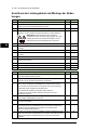
Standard E/A-Anschlüsse
Der folgende Anschlussplan zeigt die Standard-E/A-Anschlüsse des Makros Werkseinstel-
lung des ACS880 Haupt-Regelungsprogramms.
Leitergrößen und Anzugsmomente der Klemmen der Regelungskarte: 0,5 ... 2,5 mm
2
(24 - 12 AWG) und 0,5 Nm (5 lbf·in) für Litzen und massive Leiter.

20 DE – Kurzanleitung für die Installation
DE
DA
ES
FI
FR
IT
NL
PL
PT
RU
SV
TR
ZH
Relaisausgänge XRO1…XRO3
Startbereit
250 V AC / 30 V DC
2 A
NO
13
COM
12
NC
11
Läuft
250 V AC / 30 V DC
2 A
NO
23
COM
22
NC
21
Störung(-1)
250 V AC / 30 V DC
2 A
NO
33
COM
32
NC
31
Eingang für externe Spannungsversorgung XPOW
24 V DC, 2 A
GND
2
+24VI
1
Referenzspannungsausgang und
Analogeingänge
J1, J2, XAI
AI1/AI2 Auswahl Strom/Spannung
AI1: U AI2: U
AI1: I AI2: I
Standardmäßig nicht benutzt.
0(4)…20 mA, R
in
= 100 Ohm
AI2-
7
AI2+
6
Drehzahlsollwert
0(2)…10 V, R
in
> 200 kOhm
AI1- 5
AI1+
4
Masse AGND
3
-10 V DC, R
L
1…10 kOhm -VREF 2
10 V DC, R
L
1…10 kOhm +VREF 1
Analogausgänge XAO
Motorstrom
0…20 mA, R
L
< 500 Ohm
AGND
4
AO2
3
Motordrehzahl U/min
0…20 mA, R
L
< 500Ohm
AGND
2
AO1
1
Umrichter-Umricher-Verbindung J3, XD2D
Umrichter-Umrichter-Kommunikation
Abschlusswiderstand
3)
ON OFF
Umrichter-Umrichter-Verbindung (D2D)
Shield
4
BGND
3
A
2
B
1
Sicher abgeschaltetes Drehmoment (STO) XSTO
Sicher abgeschaltetes Drehmoment (STO).
Beide Kreise müssen für den Start des Antriebs
geschlossen sein.
IN2
4
IN1
3
SGND
2
OUT
1
Digitaleingänge XDI
Standardmäßig nicht benutzt. DI6
6
Konstantdrehzahl 1 (1 = Ein) DI5
5
Auswahl Beschl./Verzög.-Rampen DI4
4
Quittierung DI3
3
Vorwärts (0) /Rückwärts (1) DI2
2
Stopp (0) / Start (1) DI1
1
Digitaleingänge/-ausgänge XDIO
Ausgang: Läuft DIO2
2
Ausgang: Startbereit DIO1
1
Schalter Masse-Auswahl J6
Hilfsspannungsausgang, Digitaleingang-Sperre XD24
Digitaleingang/-ausgang Masse DIOGND
5
+24 V DC 200 mA
1)
+24VD 4
Digitaleingang Masse DICOM
3
+24 V DC 200 mA
1)
+24VD 2
Startfreigabe DIIL
1
Anschluss für das Sicherheitsfunktionsmodul
X12
Anschluss für das Bedienpanel X13
Anschluss für die Memory Unit X205
Störung
1)
Gesamtbelastbarkeit dieser
Ausgänge:
4,8 W (200 mA / 24 V)
minus der Leistung, die von
DIO1 und DIO2 verbraucht
wird.
Seite wird geladen ...
Seite wird geladen ...
Seite wird geladen ...
Seite wird geladen ...
Seite wird geladen ...
Seite wird geladen ...
Seite wird geladen ...
Seite wird geladen ...
Seite wird geladen ...
Seite wird geladen ...
Seite wird geladen ...
Seite wird geladen ...
Seite wird geladen ...
Seite wird geladen ...
Seite wird geladen ...
Seite wird geladen ...
Seite wird geladen ...
Seite wird geladen ...
Seite wird geladen ...
Seite wird geladen ...
Seite wird geladen ...
Seite wird geladen ...
Seite wird geladen ...
Seite wird geladen ...
Seite wird geladen ...
Seite wird geladen ...
Seite wird geladen ...
Seite wird geladen ...
Seite wird geladen ...
Seite wird geladen ...
Seite wird geladen ...
Seite wird geladen ...
Seite wird geladen ...
Seite wird geladen ...
Seite wird geladen ...
Seite wird geladen ...
Seite wird geladen ...
Seite wird geladen ...
Seite wird geladen ...
Seite wird geladen ...
Seite wird geladen ...
Seite wird geladen ...
Seite wird geladen ...
Seite wird geladen ...
Seite wird geladen ...
Seite wird geladen ...
Seite wird geladen ...
Seite wird geladen ...
Seite wird geladen ...
Seite wird geladen ...
Seite wird geladen ...
Seite wird geladen ...
Seite wird geladen ...
Seite wird geladen ...
Seite wird geladen ...
Seite wird geladen ...
Seite wird geladen ...
Seite wird geladen ...
Seite wird geladen ...
Seite wird geladen ...
Seite wird geladen ...
Seite wird geladen ...
Seite wird geladen ...
Seite wird geladen ...
Seite wird geladen ...
Seite wird geladen ...
Seite wird geladen ...
Seite wird geladen ...
Seite wird geladen ...
Seite wird geladen ...
Seite wird geladen ...
Seite wird geladen ...
-
 1
1
-
 2
2
-
 3
3
-
 4
4
-
 5
5
-
 6
6
-
 7
7
-
 8
8
-
 9
9
-
 10
10
-
 11
11
-
 12
12
-
 13
13
-
 14
14
-
 15
15
-
 16
16
-
 17
17
-
 18
18
-
 19
19
-
 20
20
-
 21
21
-
 22
22
-
 23
23
-
 24
24
-
 25
25
-
 26
26
-
 27
27
-
 28
28
-
 29
29
-
 30
30
-
 31
31
-
 32
32
-
 33
33
-
 34
34
-
 35
35
-
 36
36
-
 37
37
-
 38
38
-
 39
39
-
 40
40
-
 41
41
-
 42
42
-
 43
43
-
 44
44
-
 45
45
-
 46
46
-
 47
47
-
 48
48
-
 49
49
-
 50
50
-
 51
51
-
 52
52
-
 53
53
-
 54
54
-
 55
55
-
 56
56
-
 57
57
-
 58
58
-
 59
59
-
 60
60
-
 61
61
-
 62
62
-
 63
63
-
 64
64
-
 65
65
-
 66
66
-
 67
67
-
 68
68
-
 69
69
-
 70
70
-
 71
71
-
 72
72
-
 73
73
-
 74
74
-
 75
75
-
 76
76
-
 77
77
-
 78
78
-
 79
79
-
 80
80
-
 81
81
-
 82
82
-
 83
83
-
 84
84
-
 85
85
-
 86
86
-
 87
87
-
 88
88
-
 89
89
-
 90
90
-
 91
91
-
 92
92


ABB ACS880-04 drive modules Quick Installation Manual
- Typ
- Quick Installation Manual
in anderen Sprachen
- English: ABB ACS880-04 drive modules
- français: ABB ACS880-04 drive modules
- español: ABB ACS880-04 drive modules
- italiano: ABB ACS880-04 drive modules
- русский: ABB ACS880-04 drive modules
- Nederlands: ABB ACS880-04 drive modules
- português: ABB ACS880-04 drive modules
- dansk: ABB ACS880-04 drive modules
- polski: ABB ACS880-04 drive modules
- svenska: ABB ACS880-04 drive modules
- Türkçe: ABB ACS880-04 drive modules
- suomi: ABB ACS880-04 drive modules
Verwandte Artikel
-
ABB ACS580-04 Quick Installation Manual
-
ABB ACS880-01-115A-2 Quick Installation Manual
-
-
-
-
-
ABB ACS850-04 series Quick Installation Manual
-
-
-
ABB ACS880 Series Quick Start Up Manual