

Contents
1. Introduction 2
2. Specifications 4
3. Operation of the 1044 6
4. Operation of the 4-20mA System 10
5. Battery Replacement 12
6. Recalibration 13
7. Fault Diagnosis 15
8. Guarantee & Servicing 17
French Technical Manual 18
German Technical Manual 36
All Time Electronics' instruments are subject to
continuous development and improvement and in
consequence may incorporate minor detail changes
from the information contained herein.
1

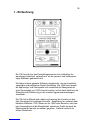
1 - Introduction
The 1044 has been designed to offer solutions in many applications from
the R&D lab to the service engineer, in fact anywhere an accurate and
low cost calibrator is needed.
We have used our experience in designing instrumentation to bring you
the most versatile and practical calibrator yet. The 1044 can source and
measure voltage and current in one compact unit and the 0.05% accu-
racy is ideal for simulation and calibration in most engineering applica-
tions.
Being virtually foolproof in operation, the 1044 combines the advantages
of digital accuracy with analog controls. Progressing from the familiar
functions of our popular 1030 calibrator, the 1044 offers more ranges,
better accuracy and the ability to measure as well as source, making it
even more of an asset.
2

3
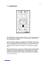
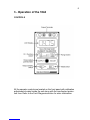
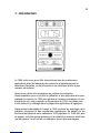
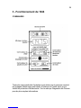
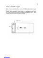
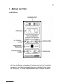
The large, easy to read LCD display shows the actual output, even
when the connected load exceeds the specifications. This impor-
tant feature eliminates the risk of large errors when connecting to
unknown loads. The display even shows if the battery becomes
low.
In the source mode, voltage up to 20v and current up to 20mA
may be generated in three ranges, whilst in current source mode,
the 1044 has a high 24V compliance voltage which is ideal power-
ing process control loops.
In the measurement mode, the range and function can be easily
selected and will operate as a multimeter. The measured input is
accurately shown on the LCD display.
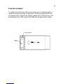
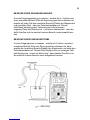
The 1044 is housed in a pocket sized, rugged ABS case and
comes with a leatherette carry case containing a compartment for
storing test leads. Connections are by standard 4mm plugs or by
simply clamping the wires under the terminals.
A single 9V battery powers the unit or an optional external 12V DC
power supply from a mains transformer, Time Electronics order
code 7643, or a cigar lighter socket in a car may be used.

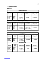
2 - Specifications
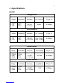
RANGES
Voltage Source
Range
Resolution
Accuracy
O/P Current
T/C per °C
0 - 200mV
0 - 2V
0 - 20V
100uV
1mV
10mV
± 0.05%
+ ± 2 Count
20mA
± 150ppm
Voltage Measure
Range
Resolution
Accuracy
O/P Voltage
T/C per °C
0 - 200mV
0 - 2V
0 - 20V
100uV
1mV
10mV
± 0.05%
+ ± 2 Count
± 150ppm
<2V = 1MΩ
<20V = 10MΩ
Current Source
Range
Resolution
Accuracy
O/P Voltage
T/C per °C
0 - 200uA
0 - 2mA
0 - 20mA
100nA
1uA
10uA
± 0.05%
+ ± 3 Count
24V Max
± 200ppm
Current Measure
Range
Resolution
Accuracy
Impedance
T/C per °C
0 - 200uA
0 - 2mA
0 - 20mA
100nA
1uA
10uA
± 0.05%
+ ± 3 Count
10Ω
± 200ppm
4

5
OUTPUT NOISE
<30ppm of f.s. on voltage, <50ppm of f.s. on current
CONNECTIONS
Connections are made by 4mm banana type connectors or may be
clamped using the wire compression feature.
BATTERIES
1 off PP3, 6AM6, MN1604 or 6LR61 type battery.
Battery life is approximately 30 Hours depending on the current sourced.
Alternatively an optional 12V power supply can be plugged into the
2.5mm socket located on the end of the unit, the tip of the plug should be
positive.
PROTECTION
The 1044 can withstand open circuits, short circuits and reverse polarity
up to 25V. Additional protection is by an internal fuse.
CONSTRUCTION
Construction is in a durable plastic case with sliding cover for battery
storage. Internally the circuit is built on a single compact PCB with plug
in display module. A carry case is also supplied for moderate protection.
DIMENSIONS AND WEIGHT
Length 142mm (5.6”) x Width 75mm (2.9”) x Height 50mm (2.0”)
Weight 280g (0.6 lbs)


7
PRELIMINARY
Operation of the 1044 can be defined as four different procedures; volt-
age source, current source, voltage measure and current measure.
For correct operation ensure that the battery low indicator is not showing
in the display. The output will only be indicated when the polarity switch is
in either ‘normal’ or ‘reverse’ positions, not in the ‘off’ position. Be certain
to check the polarity settings before connecting the unit under test. The
display will show a negative sign ‘-’ if the output is in reverse polarity
mode.
The display will show the actual applied output in source mode so if the
value alters when the unit under test is connected, the loading specifica-
tions might be exceeded. This is also useful because it eliminates poten-
tial errors when connecting to an unknown u.u.t.
Always check the mode of operation and range values before connecting
to the unit under test or to the circuit being measured. If the 1044 will not
source or measure the protection fuse has probably blown due to an ex-
cessive current being applied to the unit. This can be found inside the
1044 - refer to the Calibration section for more details.
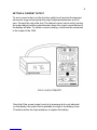
SETTING A VOLTAGE OUTPUT
To set a voltage output, set the function switch to V and set the appropri-
ate voltage range. Set to the desired voltage by turning the output adjust
multiturn potentiometer, the output voltage shown in the display will alter.
The unit under test may now be connected observing the polarity.

SETTING A CURRENT OUTPUT
To set a current output, set the function switch to mA and set the appropri-
ate current range ensuring that the output adjust potentiometer is set to
zero. Connect the unit under test. The desired current can be set by turning
the output adjust multiturn potentiometer where the output current shown in
the display will alter. To obtain a current reading, a load must be connected
to the output of the 1044.
Note that if the current output is set to its maximum but is not indicated
on the display, the output load is probably too high or the battery is low.
Therefore reduce the loop resistance or replace the battery.
8

9
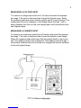
MEASURING A VOLTAGE INPUT
To measure a voltage input select the V function and select the appropri-
ate range. If the input is unknown then choose the highest range. Select
the measure mode and ensure that the polarity switch is set to normal. The
reading should now be displayed. If the display shows the digit 1 with a
blank character then the unit has over-ranged and must be switched to the
next highest range.
MEASURING A CURRENT INPUT
To measure a current input select the mA function and select the appropri-
ate range. If the input is unknown then choose the highest current range.
Select the measure mode and ensure that the polarity switch is set to nor-
mal. The reading should now be displayed. If the display shows the digit 1
with a blank character then the unit has over-ranged and must be switched
to the next highest range.

4 - Operation of the 4-20mA SYSTEM
INTRODUCTION
A common use of the 1044 would be to simulate a transducer or measure
the current flow in a transducer loop. The following brief explanation, which
is intended as a guideline only, may help when operating the 1044 in a 4-
20mA system.
THE 4-20mA SYSTEM
The basic requirement for any transducer with remote display is:
A) To use as few wires as possible.
B) That errors are not introduced into the signal from the transducer by
the effects of interference due to lead resistance.
C) To supply power to the transducer to enable amplifiers to be built into
the transducer when the signal produced by the sensing element is
too small to be transmitted without amplification.
In the 4-20mA system the transducer is supplied with D.C. power from the 2
wire line. The transducer takes the current from the line proportional to the
stimulus (i.e. pressure, temperature, etc.). By measuring the current flowing
in the line, the output of the transducer can be monitored.
Since the signal is transmitted as a current, lead resistance and voltage drop
do not affect the accuracy. The basic requirements are therefore fulfilled us-
ing just two wires - the minimum possible.
To enable a certain amount of standardisation, and to compensate for volt-
age drop or variation in the supply, transducers are designed to operate over
a wide voltage range, usually between 15 and 30 volts, and to take a ‘zero’
current of 4mA and a full scale current of 20mA.
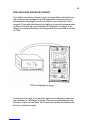
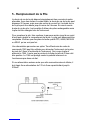
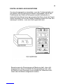
The simplest 4-20mA current loop system consists of 3 part, although often
2 parts are incorporated into the same unit. The 3 main parts are -
1) D.C. Power supply usually 24V.
2) 4 - 20mA current meter/recorder.
3) The transducer.
10

11
The D.C. power supply generates the drive power for the system and can
be considered as a battery.
THE 4-20mA meter/recorder can be a passive moving coil mA meter with
a zero offset. To obtain a reading, current must be applied.
The transducer completes the loop and allows a current flow around the
loop dependent on the level of stimulus to the transducer. It can be con-
sidered as a potentiometer changing in resistance to let between 4 and
20 mA to flow.
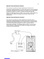
The 1044 can be used to check this system in either source or measure
modes of operation and has a 24V compliance voltage when set to cur-
rent source mode that will power a loop.

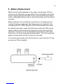
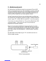
5 - Battery Replacement
Battery life is primarily dependent on the output currents drawn. With low
output currents, battery life can exceed 50 hours, but with high currents bat-
tery life may be reduced to less than 5 hours. If a short battery life is experi-
enced, rechargeable batteries may be used but the battery must be charged
externally.
Battery replacement is by sliding the rear panel up to its stopping point re-
vealing the battery compartment. The battery may now be replaced. Only
use high quality PP3, 6AM6, MN1604 or 6LR61 batteries that will not leak.
An optional mains power supply Time Electronics order code 7643 may be
used to power the instrument via the 2.5mm jack socket at the end of the
instrument. This will cut out the internal battery and power the 1044. Note
that the tip of the 2.5mm jack plug should be positive. The 1044 is protected
against reverse polarity and will not function in this state.
If an external power supply other than the above is used it must be 12V sup-
ply and up to 200mA capability.
12

13
6 - Recalibration
INTRODUCTION
Recalibration of the 1044 is essential to ensure both correct operation
and maintain accuracy. Recalibration is recommended annually.
This chapter gives calibration information.
RECALIBRATION
This instrument is calibrated before it leaves the factory and the calibra-
tion controls will not normally need adjustment, although periodic annual
re-calibration is recommended. If re-calibration is found to be necessary
then follow this calibration procedure and adjust the outputs to the pub-
lished specifications.
All readings are taken from the front panel LCD display. Once calibrated,
the 1044 would only need verification that these readings are accurate.
Equipment required for verification is a digital multimeter with an accuracy
of at least 0.01% and a voltage and current source of similar accuracy.
Suggested items would be the Time Electronics 5075 High Resolution
Digital Multimeter and the Time Electronics 5018 Voltage and Current
calibrator.
The calibrator procedure is as follows -
To adjust the trimpots follow the procedure described in fuse replace-
ment.
The zero is factory set and should not require adjustment. Set the Output
Adjust potentiometer to full scale. All adjustments are to be within 0.05%
± 1 count and are taken from the front panel LCD display.
1) Locate the 200mV trimmer pot on the rear of the LCD display. This
can be reached via a hole in the PCB. Set the 1044 to the 200mV
range and adjust the trimmer to give 200mV.
2) Locate VR7 - 20V adjust. Select the 20V range and adjust VR7 for
reading of 20V.
3) Locate VR6 - 2V adjust. Select the 2V range and adjust VR6 for a
reading of 2V.
4) Locate VR5 - 20mA adjust. Select the 20mA current range and
adjust VR5 for a reading of 20mA.

14
5) Locate VR4 - 2mA adjust. Select the 2mA current range and adjust
VR4 for a reading of 2mA.
6) Locate VR3 - 200uA adjust. Select the 200uA current range and ad-
just VR3 for a reading of 200uA.
Once these readings have been completed, verification that the LCD dis-
play is reading correctly is necessary. This is performed by injecting a
known 200mV signal into the 1044 whilst in measure mode and set to the
200mV range. If the reading is out of specification, the the unit is faulty
and must be repaired.

15
7 - Fault Diagnosis
INTRODUCTION
This section gives details of some possible problems and how to correct
them.
FAULT CHECK LIST
If the 1044 is completely dead without any indication of the display
working, check the following -
1) Battery condition - replace battery.
2) Polarity of external power unit - reverse connections.
The 1044 indicates an output but there is not an output at the termi-
nals.
1) The output protection fuse has blown. Check why this might have
blown, commonly caused by a signal being applied while still in the
source mode. Replace with the correct fuse.
Current output not available.
Is there a load connected to the output? If not, current will not flow through
the circuit.
The value selected on the display drops when the unit under test is
connected.
This is a feature of the 1044 where the ‘actual’ value is indicated. This is
probably insufficient current drive from the 1044 because the unit under
test is loading the output beyond its 20mA drive capability. Check the unit
under test for faults.
It might be due to a low battery condition. Check to see if ‘BAT’ is showing
on the LCD display.

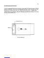
FUSE REPLACEMENT
To replace the output fuse slide the rear panel up to its stopping point re-
vealing the battery and fuse compartment. Carefully remove the old fuse
and replace with a 100mA fuse. Always replace with a 100mA fuse or seri-
ous damage to the 1044 could result. Slide the rear panel firmly closed.
16

17
8 - Guarantee & Servicing
GUARANTEE PERIOD
This unit is guaranteed against defects in materials and workmanship for a
period of one year from its delivery to the customer.
We maintain comprehensive after sales facilities and the unit can, if nec-
essary be returned to us for servicing. During this period, Time Electron-
ics Ltd will at its discretion, repair or replace the defective item.
For servicing under guarantee, the instrument type and serial number must
always be quoted, together with details of any fault and the service re-
quired. The purchaser of the instrument must prepay all shipping charges.
Time Electronics Ltd will pay return shipping charges.
This guarantee is void if servicing has been attempted by an unauthorised
person or agent. If, during the guarantee period, failure is due to misuse
or abuse of the unit, the repair will be put in hand without delay and
charged unless other instructions are received.
SERVICING AFTER GUARANTEE PERIOD
Even after the guarantee period has expired, Time Electronics Ltd., can
still service your instrument. As the manufacturer, we have the specialised
knowledge needed to keep your instrument in peak condition and we also
maintain a comprehensive spare parts service.
Please enclose details of the service required and your full company de-
tails including a contact name when returning for servicing.
RETURNING INSTRUMENTS
When returning instruments, please ensure that they have been ade-
quately packed, preferably in the original packing supplied. Time Elec-
tronics Ltd will not accept responsibility for units returned damaged.
Please ensure that all units have details of the service required and all
relevant paperwork.
Send the instrument, shipping charges prepaid to:
Time Electronics Ltd
Botany Industrial Estate, Tonbridge, Kent, TN9 1RH
Tel: +44(0)1732 355993 Fax: +44(0)1732 770312


Table des Matieres
1. Introduction 20
2. Caracteristiques Techniques 22
3. Fonctionnement du 1044 24
4. Fonctionnement du Systeme de 4-20mA 28
5. Remplacement de la Pile 30
6. Re-Etalonnage 31
7. Diagnostic des Pannes 33
8. Garantie et Entretien 35
Tous les instruments Time Electronics font l'objet
d'une politique de développement et d'amélioration
continus et, par conséquent, il est possible que l'in-
strument présente quelques changements mineurs
par rapport aux informations figurant dans ce manuel.
19
Seite wird geladen ...
Seite wird geladen ...
Seite wird geladen ...
Seite wird geladen ...
Seite wird geladen ...
Seite wird geladen ...
Seite wird geladen ...
Seite wird geladen ...
Seite wird geladen ...
Seite wird geladen ...
Seite wird geladen ...
Seite wird geladen ...
Seite wird geladen ...
Seite wird geladen ...
Seite wird geladen ...
Seite wird geladen ...
Seite wird geladen ...
Seite wird geladen ...
Seite wird geladen ...
Seite wird geladen ...
Seite wird geladen ...
Seite wird geladen ...
Seite wird geladen ...
Seite wird geladen ...
Seite wird geladen ...
Seite wird geladen ...
Seite wird geladen ...
Seite wird geladen ...
Seite wird geladen ...
Seite wird geladen ...
Seite wird geladen ...
Seite wird geladen ...
Seite wird geladen ...
Seite wird geladen ...
-
 1
1
-
 2
2
-
 3
3
-
 4
4
-
 5
5
-
 6
6
-
 7
7
-
 8
8
-
 9
9
-
 10
10
-
 11
11
-
 12
12
-
 13
13
-
 14
14
-
 15
15
-
 16
16
-
 17
17
-
 18
18
-
 19
19
-
 20
20
-
 21
21
-
 22
22
-
 23
23
-
 24
24
-
 25
25
-
 26
26
-
 27
27
-
 28
28
-
 29
29
-
 30
30
-
 31
31
-
 32
32
-
 33
33
-
 34
34
-
 35
35
-
 36
36
-
 37
37
-
 38
38
-
 39
39
-
 40
40
-
 41
41
-
 42
42
-
 43
43
-
 44
44
-
 45
45
-
 46
46
-
 47
47
-
 48
48
-
 49
49
-
 50
50
-
 51
51
-
 52
52
-
 53
53
-
 54
54


