DOEPFER A-100MNT/A-100MC Benutzerhandbuch
- Typ
- Benutzerhandbuch

A-100
Analog Modular System
A-100 Miniature Case A-100MC
A-100 Mini-Netzteil (V1)
A-100 Miniature Supply A-100MNT (V1)
Bedienungshinweise
User's Guide
doepfer Musikelektronik Gmbh

Für Anwendungen, bei denen nur einige wenige Module betrieben werden sollen,
sind die A-100-Zubehörteile
A-100MC
(Mini-Case) und
A-100 MNT
(Mini Netzteil mit
Busplatine) gedacht.
A-100MNT
besteht aus einer kleinen Stromversorgung mit integrierter Busplatine mit
4 Steckplätzen.
A-100MC
besteht aus einem kleinen Gehäuse mit 32TE Breite und eingebautem A-
100MNT. Daher gibt es eine gemeinsame Anleitung für beide Produkte.
A-100MNT und A-100MC sind für den Aufbau kleinerer Systeme gedacht, bei denen
nur wenige Module zum Einsatz kommen (z.B. Mini-Synthesizer: A-110-2/A-120/A-
130/A-140, Effekteinheit für externe Audio-Signale A-119 + Filter + LFO etc.).
Die Stromversorgung liefert die zum Betrieb der Module des Systems A-100
erforderlichen Versorgungsspannungen
+12 V
und
-12 V
sowie eine zusätzliche
Versorgungsspannung von +5 V, die einige ältere Module benötigen.
Die
maximale Strombelastbarkeit
beträgt
200 mA
für +/- 12 V
bzw.
50 mA für
die
+5 V
Versorgungsspannung.
An die Busplatine können bis zu 4 A-100-Module angeschlossen werden. Neben der
Stromversorgung liegen auf dem Bus auch die Signalleitungen CV und GATE, die bei
Bedarf zur internen Verbindung dieser Signale verwendet werden können.
Zum Lieferumfang des A-100 MNT bzw. A-100MC gehört ein
externes Netzteil
,
welches 9V Wechselspannung liefert. Es wird an den entsprechenden Stecker auf
dem Mini-Netzteil angeschlossen (bei A-100MC durch ein Loch im Gehäuse an der
linken Seite).
A
Das verwendete Netzteil muss unbedingt eine
Wechselspannung (AC)
im
Bereich
7 bis 9V
liefern und mindestens 500 mA Strom abgeben können. Mit
einem Gleichspannungsnetzteil (DC) arbeitet das A-100MNT nicht. Beim
Betrieb mit einer Wechselspannung höher als 9V kann das A-100MNT
zerstört werden.
A
Falls Sie nur das A-100 MNT bezogen haben, so sollte dieses zusammen mit
den damit betriebenen Modulen fest in ein Gehäuse eingebaut werden.
Von einem
"fliegenden Aufbau" ist dringend abzuraten
, da im Falle
leitender Verbindungen zwischen den Modulen (z.B. zufälliges gegenseitiges
Berühren von Modul-Platinen) diese beschädigt werden! Wir lehnen in
solchen Fällen die Gewährleistung ab.

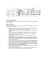
(1) Netzteilbuchse
An dieser Buchse schließen Sie das mitgelieferte externe Steckernetzteil an (9V AC /
min. 500mA)
(2) Bussteckplätze
Diese vier 16-poligen Stiftleisten dienen dem Anschluss der A-100-Module. Gehen
Sie folgendermaßen beim Einbau der Module vor:
•
Ziehen Sie das Steckernetzteil von der Buchse (1) ab.
• Ermitteln Sie die Gesamtstromaufnahme aller einzubauenden Module. Addieren
Sie dazu die Stromaufnahmen der betreffenden Module. Sie finden die
Stromangaben auf unserer Website (Info-Seite zu dem betreffenden Modul). Die
Summe darf maximal 200 mA betragen. Falls die Summe größer als 200mA
beträgt, ist das A-100MNT bzw. A-100MC für den Betrieb der Module nicht
ausreichend !
•
Prüfen Sie, ob bei jedem Modul das Modul-Anschlusskabel (Flachbandkabel) mit
einer 16-poligen Buchse am Ende zur Herstellung der Busverbindung vorhanden
ist. Bitte wenden Sie sich an den Händler, wo Sie das Modul bezogen haben, falls
das nicht bei allen Modulen der Fall sein sollte. Das Flachbandkabel selbst kann
10- oder 16-polig sein, der Bus-Stecker ist aber immer 16-polig und damit passend
zu den 16-poligen Stiftleisten des A-100MNT.
• Stecken Sie die 16-polige Buchse des Modul-Anschlusskabels vorsichtig auf eine
der 16-poligen Stiftleisten der Busplatine, die sich nahe der Stelle befindet, wo das
Modul später angeordnet werden soll.
•
Achten Sie unbedingt darauf, dass sich die
farbige Ader des Kabels
unten
befindet und dass die Buchse
bündig
(nicht seitlich oder nach oben/unten
versetzt) auf den Stiften sitzt. Die farbige Ader des Kabels muss dort sitzen, wo
sich auf der Busplatine der Aufdruck "-12V" befindet (die farbige Ader markiert den
-12V-Anschluss).
•
Andernfalls wird das Modul bei Inbetriebnahme zerstört !

Bei A-100MC gelten zusätzlich folgende Hinweise:
• Verschieben Sie die Montage-Muttern innerhalb der Profilschienen an Positionen,
die zu den Montagelöchern der Module passen. Ein kleiner Schraubenzieher oder
auch eine Büroklammer können hierzu verwendet werden.
•
Setzen Sie das Modul nun vorsichtig in das Gehäuse ein und schrauben sie es mit
den dem Modul beiliegenden Schrauben am gewünschten Platz fest.
•
Falls bereits Module montiert sind, müssen Sie unter Umständen einige
Nachbarmodule lösen, um einen besseren Zugang zur Busplatine zu bekommen.
•
Verbinden Sie erst ganz zum Schluss das Gehäuse mit dem Stromnetz und
schalten Sie es ein.
•
Testen Sie die eingebauten Module.
•
Sollten diese wider Erwarten nicht funktionieren, trennen Sie Ihr System sofort vom
Netz! Überprüfen Sie in diesem Falle noch einmal alle Steckverbindungen. Achten
Sie insbesondere auf die richtige Orientierung der Flachbandstecker am Modul und
an der Busplatine.
(3) LEDs
Die beiden LEDs dienen zur
Kontrolle der Spannungsversorgung
. Bei
ordnungsmäßen Betrieb müssen beide LEDs leuchten. Die obere LED ist die
Kontrollanzeige für +12V an, die untere für – 12V.
Sollten nicht beide LEDs leuchten, überprüfen Sie zunächst, ob an der Steckdose, in
die der Steckertrafo eingesteckt ist, Netzspannung anliegt, ob der Steckertrafo
Spannung liefert und ob nicht versehentlich ein Netzteil, das Gleichspannung (DC)
liefert, angeschlossen ist.
Verbindung von Modulen
Zur Verbindung von Modulen untereinander benötigen Sie
Verbindungskabel mit
Mono
-Klinkensteckern (∅
3.5 mm)
. Wir bieten passende Patchkabel in
verschiedenen Längen und Farben zwischen 15 cm und 2m an.

For small set-ups with a few modules only we offer the
A-100MC
(miniature case)
and
A-100MNT
(miniature power supply).
The
A-100 MNT
(
Miniature power supply / bus
) is composed of a miniature power
supply and system bus, with connectors for four modules. It’s designed to be used
in your own custom-designed case.
The
A-100MC
is a small case with 32 HP width and a built in A-100MNT.
The idea for both units is that then you can use individual A-100 modules - for
instance a miniature synthesizer or some filters or effect modules only as free-
standing pieces of equipment, which can easily be integrated with your other
instruments or recording equipment.
The A-100MNT provides the usual A-100 system requirements of
+12 V
and
-12 V
,
and an additional +5 V supply, required only for a few older modules (e.g. A-190-1).
The
maximum current loading capacity
is
200 mA
for
+12 V
and
–12V
, and
50 mA
for the +5 V supply.
The A100MNT system bus provides connections for four System A-100 modules. As
well as the power supply, it also carries the internal signals CV and GATE which may
be used if required. This depends upon the installed modules and if they use the
interal CV and/or Gate lines (e.g. Midi/USB interfaces, VCOs, ADSR).
The A-100 MNT is supplied as standard with an
external power supply
, which has
to be connected to the socket on the MNT board or to the hole at the right side of the
case if you received an A-100MC.
• The external power supply’s transformer supplies
9V alternating current (AC)
. If
you want to use another power supply instead of the one supplied, it must have a
voltage output of about
9 V AC
and
a capacity of at least 500 mA
.
• If an external power supply which produces direct current (DC) is used, the A-100
MNT or A-100MC simply won’t work!
•
If an external power supply with more than 9V is connected the A-100MNT/A-
100MC may be damaged !
• If you have ordered the A-100MNT both the A-100 MNT and any connected
modules must be
firmly fixed into a proper casing.
Any sort of
"flying
construction" is absolutely discouraged,
because if two conductors from
separate modules accidentally make contact, (for instance if the bus-bars from one
module ended up touching another module’s bus-bars), damage will almost
certainly result. In cases like that, the guarantee is definitely void.

(1) Power Supply Socket
This is the socket to which the plug from the external power supply is connected (9V
AC, min. 500mA)
(2) Bus connectors
These are the pin headers which are used to connect the A-100 modules. Up to four
modules can be connected:
•
Please calculate the total current requirement of the modules that have to be
installed into the A-100MC (or driven by the A-100MNT).
•
Check that this total is less than 200 mA. Otherwise the A-100MNT/MC is not
suitable.
•
Check if each module is equipped with a ribbon cable with a 16 pin female
connector at the open end. The ribbon cable can be 10 or 16 pin but the
female connector has to be 16 pin !
•
Now join the free end of the ribbon cable to the nearest available position on
the bus board
•
For this one has to plug the female 16 pin connector at the free end of the
ribbon cable to one of the pin headers of the bus (these are also 16 pins). Use
a pin header of the bus board that is close to the position where the module
has to be mounted later.
•
Check very carefully that it is connected so that the
coloured marking
on the
ribbon cable is at the bottom of the bus connector. The coloured marking
has to align with the "-12V" printing on the bus board next to the pin header.
•
Check also very carefully that it is
pushed fully home, not at a slight angle
and not vertically or horizontally displaced .
•
Failure to check this may result in the module’s instant destruction as soon as
the power is turned back on!
•
When you’re installing extra modules, it may be necessary to take another
module or two out, to allow you easier access to the bus board.

If the A-100MC is used please pay attention to these additional notes:
•
Move the mounting nuts inside the aluminium rails to positions that fit to the
holes of the module front panels. E.g. a small screwdriver or paper-clip may be
used for it.
•
Place the module carefully into the space in the case, and fasten it firmly in
place with the supplied screws (M3x6).
•
Repeat this procedure until all modules (and possibly blind panels) are
installed and the front of the case is fully closed.
•
Now connect the A-100MC to the power supply
•
Test out the installed modules.
•
If it doesn’t seem to be working as expected, immediately disconnect the A-
100MC from the power supply.
•
In this case, double-check all connections, making completely sure that the
ribbon cables are the right way round where they connect to the bus.
(3) LEDs
The two LEDs indicate that the power supply is working properly. Once the A-
100MNT/A-100MC is connected, both LEDs should come on. The upper LED is the
indicator for +12V, the lower for – 12V.
If both LEDs don’t come on, first of all check that mains power is available at the
socket which the A-100MNT/A-100MC power supply was connected to; then that the
mains adaptor is actually putting out voltages, and that a DC adaptor hasn’t been
used by mistake instead of the 9V AC type.
Interconnecting modules
For connecting modules to each other, you need
mono mini-jack ((
∅
3.5 mm) patch
leads
. We offer patch leads in different lengths (from 15 cm to 2 m) and colors.

Notes:
doepfer Musikelektronik GmbH
-
 1
1
-
 2
2
-
 3
3
-
 4
4
-
 5
5
-
 6
6
-
 7
7
-
 8
8


DOEPFER A-100MNT/A-100MC Benutzerhandbuch
- Typ
- Benutzerhandbuch
in anderen Sprachen
- English: DOEPFER A-100MNT/A-100MC User manual