Genelec S360-415B Floor Stand for S360 and 8xxx Benutzerhandbuch
- Typ
- Benutzerhandbuch

SICHERHEITSHINWEISE
AUFBAUANLEITUNG
KÖNIG & MEYER GmbH & Co. KG
Kiesweg 2, 97877 Wertheim, www.k-m.de
26791-000-56 Rev.04 03-80-391-00 11/18
Material
Sockel: Gußeisen, schwarz lackiert
Rohrkombination: Stahl, schwarz gepulvert
Schrauben, U-Scheiben: Stahl, verzinkt
Kunststoffteile: PA-6
Traglast max.: 70 kg
Abmessungen
Sockel: 480 x 480 mm, Höhe: 6444 - 1044 mm
Gewicht: 16 kg
Verpackung
zwei separate Kartons: a.) Sockel: 500 x 500 x 90 mm
b.) Rohr: 130 x 155 x 950 mm
Zubehör
(nicht im
Lieferumfang)
Auflageplatten für Monitore
26792-024-56: 240 x 200 mm, 1,9 kg
26792-032-56: 280 x 320 mm, 3,5 kg
26792-042-56: 420 x 380 mm, 6,1 kg
Stativadapter 26793-000-56
GENELEC 8051-408 Aufnahmeplatte 19625-330-55
GENELEC 8260-450B Aufnahmeplatte 19628-300-56
GENELEC S360-408B Aufnahmeplatte 24458-000-56
GENELEC S360-450B Haltebügel 24467-000-56
TECHNISCHE DATEN / SPEZIFIKATIONEN
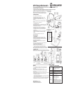
1. STATIV MONTIEREN
1.1 Bodenplatte auf dem Boden auslegen und senkrecht aufstellen
1.2 Grundrohr an die Bodenplatte halten und miteinander verschrauben...
1.3 ...mittels zweier Inbusschrauben M8 x 25 mm und U-Scheiben ø 8,4 mm
1.4 Hierzu Inbusschlüssel SW6 benutzen
Anschließend Bodenplatte mit Stativ vorsichtig auf den Boden stellen
2. VERKABELUNG
Falls gewünscht, können im Innern des Statives Kabel durchgeführt werden:
A - das Signalkabel (XLR, Kaltgerätestecker, Speakon)
B - bei Bedarf auch eine stromführende Zuleitung
2.1 Dazu Stativ auf die Seite legen und mit dem Monitorstecker voran
2.1 das Kabel von unten durch den Sockel und das Rohr schieben bis es...
2.2 ...oben am seitlichen Kabelausgang (35 x 50 mm) das Rohr wieder verlässt
2.3 Die Bodenplatte verfügt über eine Kabelöffnung (10 mm hoch, 50 mm breit)
3. HÖHENVERSTELLUNG
WARNUNG! Beim Wechsel des Standortes oder Verstellen der Höhe ist der Monitor stets
vom Stativ zu nehmen, es sei denn er ist verschraubt. Ggf. mit mehreren Personen arbeiten.
WARTUNG
ZIEL: Erhalt der Gängigkeit, der Tragkraft und der Sicherheit der Installation mittels:
ZIEL: - schonendem Umgang, - beständiger Pflege, - erforderlicher Instandhaltung
MASSNAHMEN:
- SICHTPRÜFUNG vor und erneut nach der Benutzung vornehmen
- Beschädigte Stative dürfen nicht eingesetzt werden, bzw. erst nach einer Reparatur
- Bei wackeligem Stand sind Stativ (Filzunterlagen, Verschraubung) und der Boden
- (Eignung) zu prüfen
- PFLEGE- und INSTANDHALTUNGsarbeiten haben stets im unbelasteten Zustand stattzufinden
- Mögliche Gefährdungen bei Wartungsarbeiten sind Quetschungen der Finger:
- a. durch das Gewicht der Bodenplatte:
- a. Schutz durch aufmerksame Handhabung, Benutzung von Handschuhen, Sicherheitsschuhen
- b. zwischen Boxenauflageplatte und Klemmgriff:
- b. Schutz durch: Mindestabstand bauartbedingt 50mm, aufmerksame Handhabung, Handschuhe
- Zur Reinigung ein leicht feuchtes Tuch und ein nicht scheuerndes Reinigungsmittel benutzen
- Anderweitige Maßnahmen wie z.B. periodische Schmierung etc. sind nicht erforderlich
- Max. Tragkraft: 70 kg bei zentrischer Belastung
- Wir empfehlen beim Aufbau mit 2 oder ggf. 3 Personen zu arbeiten
- Auf tragfähigen und ebenen Untergrund/Boden achten
- Bodenplatte mit Vorsicht handhaben, insbesondere bei Montage nicht
- fallenlassen
- Für feste Schraubverbindungen zwischen Bodenplatte und Grundrohr
- sorgen
- Der Sicherungsbolzen muss stets installiert sein
- (Kap. HÖHENVERSTELLUNG)
- Kabel, die im Rohr verlaufen, sind v.a. an den Öffnungen durch geeignete
- Maßnahmen gegen Durchscheuern zu schützen (z.B. Schutzschläuche);
- im Zweifelsfall Fachmann zu Rate ziehen
- Die hochwertigen Parkettschoner sind so weit wie möglich frei von
- Weichmachern; zum Schutz von ganz besonders empfindlichen Böden
- (z.B. bestimmte Parkettsorten) sollte ggf. eine rutschfeste Unterlage
- verwendet werden
- Die Adapter für die GENELEC-Monitore müssen stets fest mit dem Stativ
- verschraubt sein; Festigkeit dieser Schraubverbindung regelmäßig
- überprüfen
- Periodisch den ordnungsgemäßen Sitz des Monitors prüfen
Vielen Dank, daß Sie sich für dieses Produkt entschieden haben. Diese
Anleitung informiert Sie über alle wichtigen Schritte bei Aufbau und Hand-
habung. Wir empfehlen, sie auch für den späteren Gebrauch aufzubewahren.
26791 Design Monitorstativ
- höhenverstellbares Monitorstativ mit standfestem, formschönen Guss-Sockel für den repräsentativer Auftritt
- Kabelführung innerhalb des Standrohres möglich
- ausrüstbar mit den universellen K&M-Aufnahmeplatten (Art.-Nr. 26792) sowie herstellerspezifischen Adaptern
- Tragkraft: max. 70 kg; stufenweise höhenverstellbar von 644 - 1044 mm; Gewicht: 16 kg
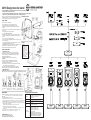
1. STATIV MONTIEREN
2. VERKABELUNG
4. ABMESSUNGEN - Benutzung - Transport – Verpackung
- WARNUNG!
- Die Kabel sind vor allem
- an den Ein- und Austritts-
- öffnungen mit geeigneten
- Maßnahmen (z.B. Schutz-
- schläuche) gegen Durch-
- scheuern zu schützen.
- Bei stromführenden
- Kabeln hat die Installation
- durch einen Fachmann
- mit entsprechenden
- Sicherheitskenntnissen
- zu erfolgen.
minimaler
Quetsch-
Spalt
Klemmschraube
etwas lösen
Griff ziehen bis sich der
Sicherungsbolzen nicht
mehr im Eingriff befindet
Auszugroh ein-
bzw. ausfahren
Sicherungsbolzen in Loch
einrasten lassen und Klemm-
griff wieder fest anziehen

SAFETY NOTES
SETUP INSTRUCTIONS
KÖNIG & MEYER GmbH & Co. KG
Kiesweg 2, 97877 Wertheim, www.k-m.de
26791-000-56 Rev.04 03-80-391-00 11/18
Material
Base: Die-cast, lacquered, black
Tube combination: Steel, powder coating, black
Screws, washers: Steel, galvanized
Plastic parts: PA-6
Load max.: 70 kg
Dimensions
Base: 480 x 480 mm, Height: 6444 - 1044 mm
Weight: 16 kg
Box
two separate boxes: a.) Base: 500 x 500 x 90 mm
b.) Tube: 130 x 155 x 950 mm
Accessories
(not included)
Bearing plates for monitors
26792-024-56: 240 x 200 mm, 1.9 kg
26792-032-56: 280 x 320 mm, 3.5 kg
26792-042-56: 420 x 380 mm, 6.1 kg
Adapter 26793-000-56
GENELEC 8051-408 Stand plate 19625-330-55
GENELEC 8260-450B Stand plate 19628-300-56
GENELEC S360-408B Stand plate 24458-000-56
GENELEC S360-450B U-bracket 24467-000-56
TECHNICAL DATA / SPECIFICATIONS
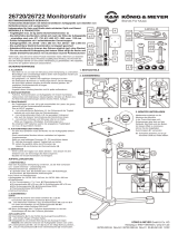
1. ASSEMBLE THE STAND
1.1 Place the floor plate on the floor and the stand it up vertically
1.2 Hold the base tube on the base plate and screw them together...
1.3 ...using two hexagon screws M8 x 25 mm and washers ø 8.4 mm
1.4 Use allen wrench SW6 for this
Then Carefully place the base plate and stand on the floor
2. WIRING
If desired, the cable can be guided through the stand shaft:
A - the signal cable (XLR, cooling equipment plugs, Speakon)
B - if needed, also an electrical outlet
2.1 For this place the stand on its side and starting with the monitor plug
2.1 place it in through the base and the tube until it...
2.2 ...reaches and goes through the lateral cable exit (35 x 50 mm)
2.3 The base plate has a cable opening (10 mm high, 50 mm wide)
3. HEIGHT ADJUSTMENT
WARNING! When switching the location of the stand or adjusting the height of the monitor be sure to
always remove the monitor from the stand. To accomplish this several individuals may be needed.
MAINTENANCE
OBJECTIVE: Maintain the operability, load bearing weight and safety of the installation by:
OBJECTIVE: - careful handling, continuous care, and performing the required upkeep
MEASURES:
- VISUAL INSPECTION prior to and after use.
- Damaged stands may not be used i.e. may only be used after they have been repaired
- In the case the stand is not stable check felt pads, connections and surface to ensure suitability
- CARE AND UPKEEP work is always to be performed without the monitors being attached
- Possible risks when performing maintenance include pinching or wedging of fingers and hands:
- a. through the weight of the base plate:
- a. Protection through careful handling, wearing gloves and safety shoes
- b. risk between the monitor support bracket and clamp grip:
- b. Protection through: Minimum distance is 50 mm (depending on the equipment), careful
- b. handling, gloves
- To care for the product, use a damp cloth and a non-abrasive cleaning agent
- Other measures such as e.g. periodic lubrication is not required
- Max. load: 70 kg - centered weight
- We recommend that 2 to 3 people assemble the system
- Be sure that the surface is weight bearing, sturdy and level
- Handle the base plate with care, in particular do not drop it during
- assembly
- Ensure that the screw connections between the base plate and the base
- tube are tight
- The safety bolt must be operational at all time
- (see Section HEIGHT ADJUSTMENT)
- Cables that are inside the tubes are to be protected against abrasion
- (for example protective tubing), specifically where the cables come out of
- the tubes;
- In case of doubt consult a qualified technician.
- The end caps are made of high-quality material and to the extent possible
- free of softening agents;
- To protect particularly delicate floors (possibly certain wood floor types)
- a slip resistant pad should be used, if needed.
- The GENELEC monitor adapter must be securely screwed into the stand;
- Routinely, check to ensure that the screw connection is tight
- Regularly, check that the monitor is properly centered
Thank you for choosing this product. This instruction manual informs you
about the important steps to set up and handle the product. We recommend
to keep the manual in a separate place for a possible later use.
26791 Design monitor stand
- Height adjustable Monitor Stand with stable, attractive die-cast base that makes a statement
- Cable guide within the stand tube possible
- equipped with universal K&M bearing plate (Product No 26792) and manufacturer-specific adapters
- Load: max. 70 kg; variable height adjustment from 644 - 1044 mm; Weight: 16 kg
1. ASSEMBLE THE STAND
2. WIRING
4. DIMENSIONS - Use - Transport - Packaging
- WARNING!
- Ensure the cables are
- protected at the entry and
- exit openings by imple-
- menting the necessary
- measures (e.g. protective
- sleeves) to protect from
- wear and tear.
- In the case of electrical
- cords, these cords are to
- be installed by a qualified
- technician with the
- required safety expertise.
minimal
gap
Unscrew the
clamp screw a
bit
Pull the handle until the
safety pin is no longer in
the locked position
Extend or
retract the
extension tube
Let the safety pin click into
the desired hole and re-
tighten the clamp handle
-
 1
1
-
 2
2


Genelec S360-415B Floor Stand for S360 and 8xxx Benutzerhandbuch
- Typ
- Benutzerhandbuch
in anderen Sprachen
Verwandte Artikel
-
Genelec 8260-450B Stand plate for 8361 Iso-Pod Benutzerhandbuch
-
-
-
-
-
-
Andere Dokumente
-
König & Meyer K&M 16090 Benutzerhandbuch
-
ARRI Skypanel DoPchoice SnapBag Benutzerhandbuch
-
 OUT MEYER Benutzerhandbuch
-
 K&M Stands 14047 Benutzerhandbuch
-
König & Meyer 80310 Quick Manual
-
 KONIG MEYER 26720-022-55 Benutzerhandbuch
-
-
-
K&M 21436 Bedienungsanleitung


