
GB
Betriebsanleitung Fernsteller RTP 1, Seite 1-4
Operating instructions Remote control RTP 1, page 5-8
GB
Art. Nr.: 099-008076-EWM20 1 / 8 16.04.02
Der Fernsteller darf nur mit Geräten der TRITON-Serie betrieben werden.
Diese Betriebsanleitung ist nur in Verbindung mit der entsprechenden
Gerätebetriebsanleitung gültig!
Sicherheitsmaßnahmen in der Standardbetriebsanleitung beachten!
Inhaltsverzeichnis............................................................................................................................Seite
1 Beschreibung............................................................................................................................... 1
1.1 Die Betriebsarten................................................................................................................. 1
2 Technische Daten........................................................................................................................ 1
3 Bedienelemente........................................................................................................................... 2
4 Inbetriebnahme............................................................................................................................ 3
4.1 Betriebsart Pulsen............................................................................................................... 3
4.2 Betriebsart Punkten............................................................................................................. 3
4.3 Standard-Betrieb................................................................................................................. 3
5 Schaltplan..................................................................................................................................... 4
1 Beschreibung
Der Fernsteller kann in den Schweißverfahren
E-Hand- oder WIG- betrieben werden.
Der Fernsteller kann zum Pulsen, Punkten oder
im Standard-Betrieb zur einfachen
Schweißstromregulierung eingesetzt werden.
Die Höhe des Schweißstromes ist prozentual
abhängig von der Einstellung am Schweißgerät
(Drehknopf „AMP“).
1.1 Die Betriebsarten
• Betriebsart Pulsen
Der Schweißstrom wird periodisch zwischen dem Pulsstrom und Pausenstrom hin- und
hergeschaltet. Puls- und Pausenzeiteinstellung können separat mit Drehknöpfen vorgenommen
werden.
• Betriebsart Punkten
Der Schweißstrom wird über eine definiert einstellbare Zeit eingeschaltet.
Der Drehknopf zur Einstellung ist mit der Doppelfunktion „Pulszeit / Punktzeit“ belegt. Beim
Punkten ist der eingestellte Wert mit dem Faktor 10 zu multiplizieren.
• Betriebsart Standard
Der Fernsteller wird ausschließlich zur Einstellung von
Schweißstrom „I1 (%AMP)“ und „I2 (%I1)“ verwendet.
2 Technische Daten
RTP 1
Anschlußkabel
5m
Maße (L x B x H)
260 x 147 x 75mm
Gewicht
1,5kg

GB
Betriebsanleitung Fernsteller RTP 1, Seite 1-4
Operating instructions Remote control RTP 1, page 5-8
GB
Art. Nr.: 099-008076-EWM20 2 / 8 16.04.02
3 Bedienelemente
RT P 1
RT P 1
t
1
t
1
I
1
I
1
I
1
I
1
I
2
I
2
t
1
t
1
t
2
t
2
0
50
75
100
25
0
25
50
75
100
t (sek)
2
t (sek)
2
0,05
0,5
1
1,5
2
t (sek)
1
t (sek)
1
x10
0,05
0,5
1
1,5
2
I
1
I
1
I
2
I
2
I
1
I
1
(% AMP)
(% I )
1
(% I )
1
I
2
I
2
A1
B1
C1
D1
E1
F1
G1
H1
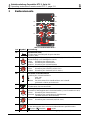
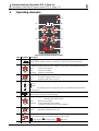
Abb.1: Handfernsteller RTP 1
Pos. Symbol Beschreibung
A1
I
1
I
1
I
2
I
2
t
1
t
1
t
2
t
2
Signalleuchte (LED)
Leuchtet wenn Schweißgerät eingeschaltet bzw.
Pulsstrom fließt.
B1
0
50
75
100
25
I
1
I
1
(% AMP)
Drehknopf I
1
(%AMP) (prozentual in Abhängigkeit der Schweiß-
stromeinstellung am Schweißgerät 0-100%).
Pulsen: Einstellung des Pulsstromes,
Punkten: Einstellung des Punktstromes,
Standard: Einstellung des Schweißstromes
C1
t (sek)
1
t (sek)
1
x10
0,05
0,5
1
1,5
2
Drehknopf Puls- / Punktzeit (Doppelfunktion):
Pulsen: Einstellung der Pulszeit (0,05 bis 2sec).
Punkten: Einstellung des Punktzeit (0,5 bis 20sec).
D1 Umschalter Schweißverfahren
Einstellung des Schweißverfahrens
WIG oder
E-Hand.
Beachte: Der Umschalter für Schweißverfahren am Schweiß-
gerät muß auf WIG geschaltet sein.
E1
I
1
I
1
I
2
I
2
t
1
t
1
t
2
t
2
Signalleuchte
Leuchtet wenn Pausenstrom fließt.
F1
0
25
50
75
100
(% I )
1
(% I )
1
I
2
I
2
Drehknopf I
2
(%I
1
)
(prozentual in Abhängigkeit der Pulsstromeinstellung I
1
am Fernsteller 0-100%).
Pulsen: Einstellung des Pausenstromes
Standard: Einstellung des verminderten Schweißstromes
(abrufbar mit dem 2. Brennertaster)
G1
t (sek)
2
t (sek)
2
0,05
0,5
1
1,5
2
Drehknopf: Pausenzeit
Pulsen: Einstellung der Pausenzeit (0,05 bis 2sec).
H1
I
1
I
1
I
2
I
2
Drehschalter:
Mit dem Drehschalter kann zwischen drei Betriebsarten gewählt werden:
Pulsen / Standard / Punkten
I1 Anschlußstecker mit 5m Anschlußleitung, 19pol. (ohne Abb.)

GB
Betriebsanleitung Fernsteller RTP 1, Seite 1-4
Operating instructions Remote control RTP 1, page 5-8
GB
Art. Nr.: 099-008076-EWM20 3 / 8 16.04.02
4 Inbetriebnahme
Dieser Fernsteller darf nur an die Fernstelleranschlußbuchse angeschlossen werden, die
als solche in der Betriebsanleitung des Schweißgerätes ausgewiesene ist!
Der Anschluß darf niemals an einem Drahtvorschubgerät erfolgen!
Fernstelleranschlußstecker nur bei ausgeschaltetem Schweißgerät in die Fernstellerbuchse
einstecken und verriegeln.
• Fernsteller am Schweißgerät anschließen (Standardbetriebsanleitung des Schweißgerätes
beachten).
• Schweißverfahren WIG oder E-Hand mit Umschalter (D1) einstellen.
• Pulsen , Punkten oder Standard-Betrieb mit Umschalter (H1) einstellen.
• Maximalen Schweißtstrom am Schweißgerät vorwählen (Drehknopf „AMP“).
Der Drehknopf „AMP %“ am Schweißgerät ist ohne Funktion.
4.1 Betriebsart Pulsen
• Pulsstrom (B1) und Pausenstrom (F1) am Fernsteller einstellen
Bsp. mit folgenden Einstellungen:
maximaler Schweißstrom am Schweißgerät: 120A
Pulsstrom am Fernsteller: 50%
Pausenstrom am Fernsteller: 25%
Ergebnis:
Pulsstrom = 60A (120A x 50%)
Pausenstrom = 15A (120A x 50% x 25%)
• Pulszeit t
1
(C1) und Pausenzeit t
2
(G1) einstellen.
4.2 Betriebsart Punkten
• Punktstrom (B1) am Fernsteller einstellen.
• Punktzeit (C1) einstellen (Der Drehknopf ist mit einer Doppelfunktion belegt, daher ist der
eingestellte Wert mit 10 zu multiplizieren).
Bsp. mit folgenden Einstellungen:
Punktzeit: 1,5sec.
Ergebnis:
1,5sec. x 10 = Punktzeit 15sec.
4.3 Standard-Betrieb
• Schweißstrom (B1) einstellen
(0-100% von Drehknopf „AMP“ am Schweißgerät)
• Verminderten Schweißstrom (F1) einstellen (0-100% von Drehknopf (B1)),
abrufbar mit dem 2. Brennertaster

GB
Betriebsanleitung Fernsteller RTP 1, Seite 1-4
Operating instructions Remote control RTP 1, page 5-8
GB
Art. Nr.: 099-008076-EWM20 4 / 8 16.04.02
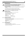
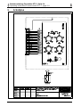
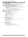
5 Schaltplan

GB
Betriebsanleitung Fernsteller RTP 1, Seite 1-4
Operating instructions Remote control RTP 1, page 5-8
GB
Art. Nr.: 099-008076-EWM20 5 / 8 16.04.02
The remote control should be operated only with machines of the TRITON series. These
operating instructions are valid only in combination with the operating instructions for the
relevant machine
Observe the safety precautions listed in the standard operating instructions!
Index .................................................................................................................................................page
1 Description................................................................................................................................... 5
1.1 The operating modes ..........................................................................................................5
2 Technical data.............................................................................................................................. 5
3 Operating elements..................................................................................................................... 6
4 Commissioning............................................................................................................................ 7
4.1 Pulse mode operation .........................................................................................................7
4.2 Spot mode operation........................................................................................................... 7
4.3 Standard operation.............................................................................................................. 7
5 Circuit diagram ............................................................................................................................ 8
1 Description
The remote control can be used for either MMA or
TIG welding processes.
The remote control can be used for pulse or spot
mode operation or for simple welding current
regulation in the standard operating mode.
The percentage strength of the welding current
depends on the setting of the "AMP" rotary dial
on the welding machine.
1.1 The operating modes
• Pulse mode
The welding current is periodically switched to and for between pulse current and break current.
Rotary dials permit separate settings of pulse and break times.
• Spot mode
The welding current is switched on for a defined, adjustable time setting.
For this purpose, the rotary dial has been assigned the dual functions “pulse time/spot time”. For
spot mode operation, the setting figure must be multiplied by 10.
• Standard operation
The remote control is used solely to set the welding current at “I1 (%AMP)“ and “I2 (%I1)“.
2 Technical data
RTP 1
Connector cable
5 m
Dimensions (L x W x H)
260 x 147 x 75 mm
Weight
1.5 kg

GB
Betriebsanleitung Fernsteller RTP 1, Seite 1-4
Operating instructions Remote control RTP 1, page 5-8
GB
Art. Nr.: 099-008076-EWM20 6 / 8 16.04.02
3 Operating elements
RT P 1
t
1
t
1
I
1
I
1
I
1
I
1
I
2
I
2
t
1
t
1
t
2
t
2
0
50
75
100
25
0
25
50
75
100
t (sek)
2
t (sek)
2
0,05
0,5
1
1,5
2
t (sek)
1
t (sek)
1
x10
0,05
0,5
1
1,5
2
I
1
I
1
I
2
I
2
I
1
I
1
(% AMP)
(% I )
1
(% I )
1
I
2
I
2
A1
B1
C1
D1
E1
F1
G1
H1
Fig.1: RTP 1 manual remote control
Item
Symbol
Description
A1
I
1
I
1
I
2
I
2
t
1
t
1
t
2
t
2
Signal light (LED)
Lights up when welding machine is switched on or when pulse current is flowing.
B1
0
50
75
100
25
I
1
I
1
(% AMP)
Rotary dial I
1
(%AMP)
(0-100% percentage depends on the welding current setting on the welding machine).
Pulse: Pulse current setting,
Spot: Spot current setting,
Standard: Welding current setting
C1
t (sek)
1
t (sek)
1
x10
0,05
0,5
1
1,5
2
Rotary dial pulse/spot time (dual functions):
Pulse: Pulse time setting (0.05 to 2 sec.).
Spot: Spot time setting (0.5 to 20 sec.).
D1
Changeover switch to select welding process Selects welding operation
TIG or
MMA.
Note: The welding process changeover switch on the welding machine must be
switched to TIG.
E1
I
1
I
1
I
2
I
2
t
1
t
1
t
2
t
2
Signal light
Lights up when the break current is flowing.
F1
0
25
50
75
100
(% I )
1
(% I )
1
I
2
I
2
Rotary dial I
2
(%I
1
) (0-100% percentage depends on the pulse current
setting on the remote control).
Pulse: Break current setting
Standard: Reduced welding current setting
(ready to be called up by the 2
nd
torch trigger)
G1
t (sek)
2
t (sek)
2
0,05
0,5
1
1,5
2
Rotary switch: Break time
Pulse: Break time setting (0.05 to 2 sec).
H1
I
1
I
1
I
2
I
2
Rotary switch:
Three operating modes can be selected via the rotary switch:
pulse mode / standard mode / spot mode
I1
Connector plug with 19-pole connector cable, 5 m (no illustr.)

GB
Betriebsanleitung Fernsteller RTP 1, Seite 1-4
Operating instructions Remote control RTP 1, page 5-8
GB
Art. Nr.: 099-008076-EWM20 7 / 8 16.04.02
4 Commissioning
This remote control may only be connected to the remote control connection socket
identified as such in the welding machine operating instructions.
It must never be connected to a wire feed unit.
The welding machine must always be switched off before the remote control plug is
plugged into the remote control socket and locked.
• Connect the remote control to the welding machine (observe standard operating instructions for
the welding machine).
• Set changeover switch (D1) to TIG or MMA welding process.
• Set changeover switch (H1) to pulse, spot or standard operating mode.
• Preselect maximum welding current on the “AMP” rotary dial of the welding machine.
The "AMP %" rotary dial on the welding machine has no function.
4.1 Pulse mode operation
• Set pulse (B1) and break (F1) current on the remote control,
as with e.g. following settings:
Maximum welding current on the welding machine: 120A
Pulse current on remote control: 50%
Break current on remote control: 25%
Result:
Pulse current = 60A (120A x 50%)
Break current = 15A (120A x 50% x 25%)
• Set pulse time t
1
(C1) and break time t
2
(G1).
4.2 Spot mode operation
• Set spot current (B1) on remote control.
• Set spot time (C1) (the rotary dial has been assigned dual functions, and thus the value of the
setting must be multiplied by 10),
as with e.g. following settings:
Spot time: 1.5 sec.
Result:
1.5 sec. x 10 = spot time 15 sec.
4.3 Standard operation
• Set welding current (B1)
(0-100% on “AMP“ rotary dial on welding machine)
• Set reduced welding current (F1) (0-100% on rotary dial (B1)),
ready to be called up by the 2
nd
torch trigger

GB
Betriebsanleitung Fernsteller RTP 1, Seite 1-4
Operating instructions Remote control RTP 1, page 5-8
GB
Art. Nr.: 099-008076-EWM20 8 / 8 16.04.02
5 Circuit diagram
-
 1
1
-
 2
2
-
 3
3
-
 4
4
-
 5
5
-
 6
6
-
 7
7
-
 8
8


in anderen Sprachen
- English: EWM RTP 1
Andere Dokumente
-
Primare I22 Benutzerhandbuch
-
ESAB DTF 400 AC / DC Benutzerhandbuch
-
-
-
-
-
-
-
Cebora 343 TIG Sound DC 5100/T Benutzerhandbuch
-
ESAB DTG 405 Benutzerhandbuch