
PAPI004206-INTER5 - Version 21.08
Instructions for use
Instrucciones de uso
Instruções de utilização
Istruzioni per l uso
Gebrauchsanweisung
Doseur automatique par contrôle ORP
Automatic doser by ORP control
Dosificador automático por control ORP
Dosagem automática por controlo ORP
Dosaggio automatico con controllo ORP
Chlordosierung durch ORP-Regelung
FRANCAIS
ENGLISH
ESPAÑOL
PORTUGUÊS
ITALIANO
DEUTSCH

2
1. ............................................................................................................................................ 3
2. PRECISIONS SUR LE CONTROLE ORP ............................................................................................................................ 4
3. COFFRET ELECTRONIQUE ............................................................................................................................................. 5
3.1. Interface et indicateurs ........................................................................................................................................ 5
3.2. Opérations de base .............................................................................................................................................. 5
3.3. Signification des menus ........................................................................................................................................ 5
3.4. Fonctionnalités ..................................................................................................................................................... 6
3.4.1. Réglage du dosage de chlore ................................................................................................................... 6
3.4.2. Injection manuelle de chlore ................................................................................................................... 6
3.4.3. Calibrage de la sonde ORP ....................................................................................................................... 6
3.4.4. Ajustage de la mesure ORP ..................................................................................................................... 7
3.4.5. Réglage de la consigne ORP ..................................................................................................................... 7
3.4.6. Réglage du délai entre chaque injection de chlore (temps de dilution) ................................................. 8
3.4.7. Réglage du délai de démarrage du dosage de chlore ............................................................................. 8
3.4.8. Spécification du taux de concentration du chlore utilisé ........................................................................ 8
3.5. Alarmes ................................................................................................................................................................. 8
4. GARANTIE ..................................................................................................................................................................... 9
SOMMAIRE FRANCAIS

3
1.
11
2
4
6
8
H
16
10
1
9
9
15
13
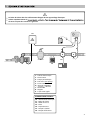
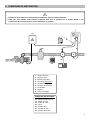
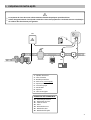
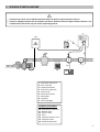
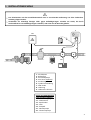
1: Coffret électronique
2: Filtre lesteur
3: Pompe péristaltique
4: Pool Terre (en option)
5: Porte-sonde
6
7: Sonde ORP
8: Support
9: Tuyau semi-rigide
ELEMENTS NON FOURNIS :
10 : Alimentation électrique
11 : Bidon de chlore
12 : Câble de cuivre
13 : Filtre
14 : Piquet de terre
15 : Pompe à chaleur
16 : Pompe de filtration
4
8
7
5
I
Le bidon de chlore doit être suffisamment éloigné de tout appareillage électrique.
Utiliser impérativement du
de tartre ne peut être soumis à la garantie.
14
4
12
3

4
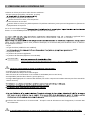
2. PRECISIONS SUR LE CONTROLE ORP
Le besoin en chlore peut varier selon diverses conditions :
- Piscine couverte (par bâche, couverture, ou volet)
- Surfréquention temporaire de la piscine
Besoin très élevé en chlore, mais temporaire.
- Piscine intérieure ou sous abri
Besoin réduit en chlore (car faible exposition à la pollution extérieure), mais qui tend à augmenter en fonction de
la fréquentation de la piscine.
Au vu de ces multiples configura
besoins. Le contrôle ORP permet de répondre à chacune de ces situations.
significatif de la
valeur soit une référence, celle-ci reste purement théorique, car la mesure ORP peut facilement varier en fonction
des paramètres suivants :
- Le pH.
- Le type de chlore (stabilisé ou non stabilisé).
- -actifs).
- La propreté du filtre.
- La présence de courants vagabonds.
- La présence de floculant (dépôt sur la sonde ORP).
La mesure ORP : -
- varie en fonction du taux de chlore libre et de tous les éléments p
IPREREQUIS INDISPENSABLES POUR UN CONTROLE ORP OPTIMAL :
- pH stable (avec un régulateur de pH).
- Taux de stabilisant compris entre 20 et 30 ppm.
- Mise à la terre de la canalisation où est installée la sonde ORP (avec un Pool Terre).
- Eau équilibrée (taux de chlore libre à 1 ppm et pH à 7,2).
- Consigne ORP appropriée à la mesure ORP affichée (une valeur comprise entre 500 et 700 mV peut être considérée
comme correcte).
e.
e.
effets du produit sur la mesure ORP disparaissent.
Influence des chloramines sur la mesure ORP : lorsque le taux de chloramines tend à augmenter, la mesure ORP
tend à diminuer.
ILe contrôle ORP ne dispense en aucun cas la nécessité de contrôler régulièrement le taux de chlore libre.

5
3. COFFRET ELECTRONIQUE
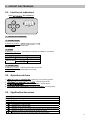
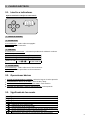
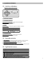
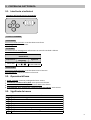
3.1. Interface et indicateurs
Visuel non contractuel :
.1: TOUCHES DE COMMANDE.
.2: VOYANT ROUGE.
Si allumé en continu :
Si clignotant : alarme déclenchée.
.3: ECRAN.
Si affichage clignotant : information en attente de validation, ou alarme.
AFFICHAGE PAR DEFAUT
Paramètre
Valeu
r affichée
Signification
Mesure ORP
De
à
De 0 à 99 mV
De
à
De 100 à 990 mV
.4: VOYANT VERT.
Si allumé en continu : coffret électronique en marche.
Si clignotant : pompe péristaltique en marche.
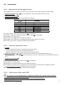
3.2. Opérations de base
: appui long sur la touche gauche.
: touches haut et bas.
Entrée dans un menu : touche droite.
Retour au menu précédent : touche gauche.
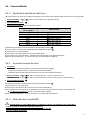
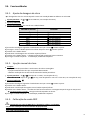
3.3. Signification des menus
MENU
FONCTIONNALITE
Réglage du dosage de chlore
Injection manuelle de chlore
Calibrage de la sonde ORP
Ajustage de la mesure ORP
Réglage de la consigne ORP
Réglage du délai entre chaque injection de chlore (temps de dilution)
Réglage du délai de démarrage du dosage de chlore
Spécification du taux de
concentration du chlore utilisé
3
4
2
1

6
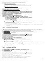
3.4. Fonctionnalités
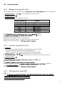
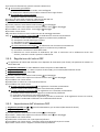
3.4.1. Réglage du dosage de chlore
Le dosage de chlore est le volume injecté égale à la consigne ORP.
Réglages possibles : de à (soit de 10 à 990 mL, par pas de 10 mL).
Réglage par défaut :
Réglage préconisé : selon le tableau ci-dessous.
VOLUME DU BASSIN
DOSAGE
1 m
3
(soit 10 mL)
10 m
3
(soit 100 mL)
30 m
3
(soit 300 mL)
50 m
3
(soit 500 mL)
60 m
3
(soit 600 mL)
100 m
3
(soit 800 mL)
120 m
3
(soit 990 mL)
1) clignote.
2) menu clignote.
3) Valider avec la touche droite.
4) Sélectionner un dosage avec les touches haut/bas.
5) Valider avec la touche droite : le dosage sélectionné se fige brièvement.
6) Appuyer sur la touche gauche
3.4.2. Injection manuelle de chlore
Fonctions :
- Amorçage de la pompe péristaltique et remplissage des tuyaux semi-rigides.
- Injection instantanée de chlore, pour une durée déterminée.
- Moyen de vérification du bon fonctionnement de la pompe péristaltique.
Réglages possibles : de à (soit une durée de 1 s à 60 s, par pas de 1 s),
Réglages possibles : puis de à (soit une durée de 1 min 10 s à 9 min 50 s, par pas de 10 s).
Réglage par défaut :
1) menu clignote.
2) Valider avec la touche droite.
3)
4) Valider avec la touche droite temps réel.
: appuyer sur la touche gauche ou droite.
5) Appuyer sur la touche gauche
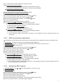
3.4.3. Calibrage de la sonde ORP
IAfin :
-
- à chaque début de saison lors de la remise en service.
- après chaque remplacement de la sonde.

7
1) rêt la filtration (et donc le coffret électronique).
2) Si la sonde est déjà installée :
a) Extraire la sonde du porte-sonde, sans la débrancher.
b) -sonde et le remplacer par le bouchon fourni.
:
Raccorder la sonde au coffret électronique.
3) Insérer la sonde dans la solution de calibrage ORP 470 mV.
4) Patienter quelques minutes, sans toucher la sonde.
5) Mettre en marche le coffret électronique.
6) clignote.
7) menu clignote.
8) Valider avec la touche droite : le message clignote.
9) Appuyer sur la touche droite.
10) -
11) Si le message le calibrage a réussi.
a) Appuyer 3 fois sur la touche gauche
b)
c) Egoutter la sonde ssuyer.
d) Installer la sonde dans le porte-sonde.
Si le message : le calibrage a échoué.
a) Appuyer 3 fois sur la touche gauche
b)
c) Refaire une tentative de calibrage, plusieurs fois si nécessaire. Si le calibrage échoue toujours, changer la
sonde et refaire un calibrage.
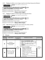
3.4.4. Ajustage de la mesure ORP
L'ajustage de la mesure ORP nécessite un appareil de mesure (non fourni) permettant d'obtenir une valeur ORP réelle.
Condition préalable : la mesure ORP doit être comprise entre 400 et 800 mV.
Réglages possibles : de - à + 100 mV par rapport à la mesure ORP, par pas de 10 mV.
Réglage par défaut : mesure ORP.
1) e que le menu clignote.
2) menu clignote.
3) Valider avec la touche droite.
4) Sélectionner une valeur avec les touches haut/bas.
5) Valider avec la touche droite.
Si le message l
Appuyer 2 fois sur la touche gauche
Si le message : l
a) Appuyer 2 fois sur la touche gauche
b) Contrôler .
c) R
ORP et effectuer un calibrage de la sonde ORP.
3.4.5. Réglage de la consigne ORP
Réglages possibles : de à (soit de 200 à 900 mV, par pas de 10 mV).
Réglage par défaut :
1) clignote.
2) menu clignote.
3) Valider avec la touche droite.
4) Sélectionner une consigne avec les touches haut/bas.
5) Valider avec la touche droite : la consigne sélectionnée se fige brièvement.
6) Appuyer sur la touche gauche

8
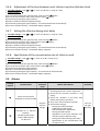
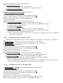
3.4.6. Réglage du délai entre chaque injection de chlore (temps de dilution)
Réglages possibles : de à (soit de 5 à 60 min, par pas de 1 min).
Réglage par défaut :
1) clignote.
2) menu clignote.
3) Valider avec la touche droite.
4) Sélectionner un délai avec les touches haut/bas.
5) Valider avec la touche droite : le délai sélectionné se fige brièvement.
6) Appuyer sur la touche gauche
3.4.7. Réglage du délai de démarrage du dosage de chlore
Réglages possibles : de à (soit de 5 à 60 min, par pas de 1 min).
Réglage par défaut :
1) clignote.
2) menu clignote.
3) Valider avec la touche droite.
4) Sélectionner un délai avec les touches haut/bas.
5) Valider avec la touche droite : le délai sélectionné se fige brièvement.
6) Appuyer sur la touche gauche
3.4.8. Spécification du taux de concentration du chlore utilisé
Réglages possibles : de à (soit de 5° à 48°, par pas de 1°).
Réglage par défaut :
1) clignote.
2) menu clignote.
3) Valider avec la touche droite.
4) Sélectionner un taux avec les touches haut/bas.
5) Valider avec la touche droite : le taux sélectionné se fige brièvement.
6) Appuyer sur la touche gauche
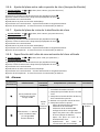
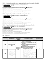
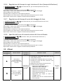
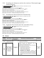
3.5. Alarmes
Affichage
clignotant
Défaut détecté
Action
automatiqu
e
immédiate
Vérifications et remèdes Acquittement
Succession
de plusieurs tentatives
de correction ORP
infructueuses
Arrêt
du dosage
de chlore
Contrôler la mesure ORP dans la piscine
vide.
raccord
Effectuer une injection manuelle de chlore.
Vérifier tous les réglages :
- Réglage du dosage de chlore.
- Calibrage de la sonde ORP.
- Ajustage de la mesure ORP.
- Réglage de la consigne ORP.
-
Réglage du délai entre chaque injection
de chlore (temps de dilution).
-
Réglage du délai de démarrage du
dosage de chlore.
- Spécification
du taux de concentration du
chlore utilisé.
Appuyer
sur la touche
droite
Ecart de + ou - 400 mV
entre la mesure ORP
et la consigne ORP
durant 48 heures

9
4. GARANTIE
Avant tout contact avec votre revendeur, merci de bien vouloir vous munir :
-
- du n° de série du coffret électronique.
- de la date d'installation de l'équipement.
- des paramètres de votre piscine (salinité, pH, taux de chlore, température d'eau, taux de stabilisant, volume de la piscine, temps de
filtration journalier, etc.).
Nous avons apporté tous nos soins et notre expérie
-faire apportés à sa fabrication, vous aviez à mettre en jeu notre garantie, celle-ci ne
atuit des pièces défectueuses de cet équipement (port aller/retour exclu).
Durée de la garantie (date de facture faisant foi)
Coffret électronique : 2 ans.
Sonde ORP : selon modèle.
Réparations et pièces détachées : 3 mois.
Les durées indiquées ci-dessus correspondent à des garanties standard. Toutefois, celles-
le circuit de distribution.
Objet de la garantie
S.A.V.
Les frais de transport aller et retour sont à la charge de l'utilisateur.
L'immobilisation et la privation de jouissance d'un appareil en cas de réparation éventuelle ne sauraient donner lieu à des indemnités.
Il appartient à celui-
Confirmer
auprès du transporteur dans les 72 h par lettre recommandée avec accusé réception.
Un remplacement sous garantie ne saurait en aucun cas prolonger la durée de garantie initiale.
oment et sans préavis, les
caractéristiques de ses fabrications.
-à-vis des tiers.
La garantie du constructeur, qui couvre les défauts de fabrication, ne doit pas être confondue avec les opérations décrites dans la
présente documentation.
être
réalisées exclusivement par des professionnels. Ces interventions devront par ailleurs être réalisées conformément aux normes en
so facto la
garantie sur l
Sont exclus de la garantie :
-
- Les dommages causés par une installation non-conforme.
- Les problèmes causés par une altération, un accident
Aucun matériel endommagé suite au non-respect des consignes de sécurité, d'installation, d'utilisation et d'entretien énoncées dans la
présente documentation ne sera pris en charge au titre de la garantie.
Tous les ans, nous apportons des améliorations à nos produits et logiciels. Ces nouvelles versions sont compatibles avec les modèles
précédents. Les nouvelles versions de matériels et de logiciels ne peuvent être ajoutées aux modèles antérieurs dans le cadre de la
garantie.
Pour plus d'informations sur la présente garantie, appelez votre professionnel ou notre Service Après-Vente. Toute demande devra être
accompagnée d'une copie de la facture d'achat.
Lois et litiges
La présente garantie est soumise à la loi française et à toutes directives européennes ou traités internationaux, en vigueur au moment
de la réclamation, applicables en France. En cas de litige sur son interprétation ou son exécution, il est fait attribution de compétence
au seul TGI de Montpellier (France).

2
1. INSTALLATION DIAGRAM ............................................................................................................................................. 3
2. DETAILS ABOUT THE ORP CHECK ................................................................................................................................. 4
3. ELECTRONICS UNIT ....................................................................................................................................................... 5
3.1. Interface and indicators ....................................................................................................................................... 5
3.2. Basic operations ................................................................................................................................................... 5
3.3. Meaning of the menus ......................................................................................................................................... 5
3.4. Features ................................................................................................................................................................ 6
3.4.1. Setting the chlorine dosage ..................................................................................................................... 6
3.4.2. Manual chlorine injection ........................................................................................................................ 6
3.4.3. Calibrating the ORP probe ....................................................................................................................... 6
3.4.4. ORP measurement adjustment ............................................................................................................... 7
3.4.5. Setting the ORP setpoint ......................................................................................................................... 7
3.4.6. Adjustment of the time between each chlorine injection (dilution time) .............................................. 8
3.4.7. Setting the chlorine dosing start delay .................................................................................................... 8
3.4.8. Specification of the concentration rate of chlorine used ........................................................................ 8
3.5. Alarms ................................................................................................................................................................... 8
4. GUARANTEE ................................................................................................................................................................. 9
TABLE OF CONTENTS ENGLISH

3
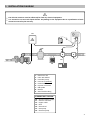
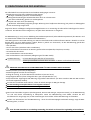
1. INSTALLATION DIAGRAM
11
2
4
6
8
H
16
10
1
9
9
15
13
1 : Electronics unit
2 : Filter with ballast
3 : Peristaltic pump
4 : Pool Terre (optional)
5 : Probe holder
6 : Injection connector
7 : ORP probe
8: Bracket
9 : Semi-flexible tubing
ELEMENTS NOT SUPPLIED :
10 : Electrical power supply
11 : Chlorine container
12 : Copper cable
13 : Filter
14 : Ground rod
15 : Heat pump
16 : Filtration pump
4
8
7
5
I
The chlorine container must be sufficiently far from any electrical equipment.
It is essential to use anti-scale liquid chlorine. Any damage to the equipment due to crystallization of scale
cannot be covered by the warranty.
14
4
12
3

4
2. DETAILS ABOUT THE ORP CHECK
The amount of chlorine required can vary depending on several conditions :
- Covered pool (by sheeting, cover or panels)
Low chlorine requirement (because there is no UV).
- Sudden rise in the number of people using the pool
Very large amounts of chlorine needed, but on a temporary basis.
- Indoor pool or sheltered pool
Reduced need for chlorine (because of low exposure to external pollution), but which tends to increase
depending on the frequency of use of the swimming pool.
Given this range of possible configurations, chlorine production must be managed according to requirements. The
ORP check enables you to react to each of these situations.
The ORP measurement (in mV), reflecting the oxidation (or reduction) potential of the water, is a major indicator of
According to the WHO, an ORP measurement of 650 mV guarantees disinfected water that is itself capable of
disinfecting. Despite the use of this value as a reference, this can only be on a theoretical level, because ORP
measurements can easily vary depending on the following parameters :
- The pH.
- The type of chlorine (stabilised or non-stabilised).
- The presence of dissolved elements that can affect the water (metals, phosphates, surfactants).
- The cleanliness of the filter.
- The presence of stray currents.
- The presence of flocculant (deposit on the ORP probe).
The ORP measurement : - is not a measurement of free chlorine levels.
The ORP measurement : - varies according to free chlorine levels and all elements in the water.
IESSENTIAL PREREQUISITES FOR AN OPTIMAL ORP CHECK :
- Stable pH (with a pH regulator).
- Stabilizer level between 20 and 30 ppm.
- Earthing of the pipe where the ORP probe is installed (with a Pool Terre kit).
- Balanced water profile (free chlorine levels at 1 ppm, and pH at 7.2).
- ORP setpoint adjusted according to the ORP measurement displayed (a value between 500 and 700 mV can be
considered as correct).
The use of sulphates is permitted, provided they remain at levels below 360 ppm.
The use of copper sulphates is strictly forbidden.
The use of borehole water is strictly prohibited.
When using a chemical (flocculant, waterline cleaning, sequestrant), check the ORP measurement before and
after use of this product. If the ORP measurement drops sharply, stop the electronics unit for a few days, until the
effects of the product on the ORP measurement disappear.
Influence of chloramines on the ORP measurement : as chloramine levels tend to increase, the ORP measurement
tends to decrease.
IThe ORP check in no case eliminates the need to regularly check free chlorine levels.

5
3. ELECTRONICS UNIT
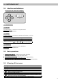
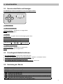
3.1. Interface and indicators
Visual of the non-contractual interface :
.1: CONTROL KEYS.
.2: RED LED.
If lit continuously : electronics unit powered off.
If flashing : alarm activated.
.3: SCREEN.
If display flashing : information awaiting confirmation, or alarm.
DESCRIPTION OF THE DEFAULT DISPLAY
Setting
Displayed value
Meaning
ORP measurement
From
to
From 0 to 99 mV
From
to
From 100 to 990 mV
.4: GREEN LED.
If lit continuously : electronics unit in operation.
If flashing : peristaltic pump on.
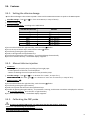
3.2. Basic operations
Switching on and off : long press on the left-hand key.
Selecting a value or data : top and bottom keys.
Confirmation of an entry / Entering a menu : right-hand key.
Cancelling an entry / Returning to the previous menu : left-hand key.
3.3. Meaning of the menus
MENU
FEATURE
Setting the chlorine dosage
Manual chlorine injection
Calibrating the ORP probe
ORP measurement adjustment
Setting the ORP setpoint
Adjustment of the time between each chlorine injection (dilution time)
Setting the chlorine dosing start delay
Specification of the concentration rate of chlorine used
3
4
2
1

6
3.4. Features
3.4.1. Setting the chlorine dosage
The chlorine dosage is the volume injected x times until the ORP measurement is equal to the ORP setpoint.
Possible settings : from to (i.e. from 10 to 990 mL, in steps of 10 mL).
Default setting :
Recommended setting : according to the table below.
VOLUME OF THE POOL DOSAGE
1 m
3
(
i.e.
10 mL)
10 m
3
(
i.e.
100 mL)
30 m
3
(
i.e.
300 mL)
50 m
3
(
i.e.
500 mL)
60 m
3
(
i.e.
600 mL)
100 m
3
(
i.e.
800 mL)
120 m
3
(
i.e.
990 mL)
1) Press and hold down the right-hand key, until the menu flashes.
2) Press the top or bottom key x times until the menu flashes.
3) Confirm by pressing the right-hand key.
4) Select a dosage with the top/bottom keys.
5) Confirm by pressing the right-hand key : the selected dosage freezes briefly.
6) Press on the left-hand key : the default display reappears.
3.4.2. Manual chlorine injection
Functions :
- Priming of the peristaltic pump and filling of semi-rigid pipes.
- Instant injection of chlorine, for a fixed period.
- Means of checking the correct operation of the peristaltic pump.
Possible settings : from to (i.e. a duration of 1 s to 60 s, in steps of 1 s),
Possible settings: then from to (i.e. a duration of 1 min 10 s to 9 min 50 s, in steps of 10 s).
Default setting :
1) Press and hold down the right-hand key, until the menu flashes.
2) Confirm by pressing the right-hand key.
3) Select an injection duration with the top/bottom keys.
4) Confirm by pressing the right-hand key : the peristaltic is running, and the timer countdown is displayed in real time.
To stop the injection : press the left- or right-hand key.
5) Press on the left-hand key : the default display reappears.
3.4.3. Calibrating the ORP probe
ITo ensure an optimal ORP check, it is imperative that the ORP probe is calibrated :
- when first commissioning the equipment.
- at the start of each season when it is commissioned.
- each time the probe is replaced.

7
1) Turn off the filtration (and therefore the electronics unit).
2) If the probe is already installed :
a) Remove the probe from the probe holder, without disconnecting it.
b) Remove the probe holder nut and replace it with the stopper supplied.
If the probe is not already installed :
Connect the probe to the electronics unit.
3) Insert the probe into the ORP 470 mV calibration solution.
4) Wait a few moments, without touching the probe.
5) Turn on the electronics unit.
6) Press and hold down the right-hand key, until the menu flashes.
7) Press the top or bottom key x times until menu flashes.
8) Confirm by pressing the right-hand key : the message flashes.
9) Press on the right-hand key.
10) Wait until one of the messages below is displayed.
11) If the message is displayed : calibration was successful.
a) Press 3 times on the left-hand key : the default display reappears.
b) Rinse the probe under running water.
c) Drain the probe without wiping it.
d) Install the probe into the probe connector.
If the message is displayed : the calibration failed.
a) Press 3 times on the left-hand key : the default display reappears.
b) Visually check the condition of the probe.
c) Try the calibration again, several times if necessary. If the calibration still fails, change the probe and
recalibrate.
3.4.4. ORP measurement adjustment
The adjustment of the ORP measurement requires a measuring device (not supplied) to obtain an actual ORP value.
Prerequisite : the ORP measurement must be between 400 and 800 mV.
Possible settings : from - to + 100 mV compared to the ORP measurement, in steps of 10 mV.
Default setting : ORP measurement.
1) Press and hold down the right-hand key, until the menu flashes.
2) Press the top or bottom key x times until menu flashes.
3) Confirm by pressing the right-hand key.
4) Select a value with the top/bottom keys.
5) Confirm by pressing the right-hand key.
If the message is displayed : the adjustment was successful.
Press 2 times on the left-hand key : the default display reappears.
If the message is displayed : the calibration has failed.
a) Press 2 times on the left-hand key : the default display reappears.
b) Visually check the condition of the ORP probe.
c) Try the adjustment again, several times if necessary. If the adjustment still fails, replace the ORP probe and
carry out a calibration of the ORP probe.
3.4.5. Setting the ORP setpoint
Possible settings : from to (from 200 to 900 mV, in steps of 10 mV).
Default setting :
1) Press and hold down the right-hand key, until the menu flashes.
2) Press the top or bottom key x times until menu flashes.
3) Confirm by pressing the right-hand key.
4) Select a setpoint with the top/bottom keys.
5) Confirm by pressing the right-hand key : the selected setpoint freezes briefly.
6) Press on the left-hand key : the default display reappears.

8
3.4.6. Adjustment of the time between each chlorine injection (dilution time)
Possible settings : from to (i.e. from 5 to 60 min, in steps of 1 min).
Default setting :
1) Press and hold down the right-hand key, until the menu flashes.
2) Press the top or bottom key x times until the menu flashes.
3) Confirm by pressing the right-hand key.
4) Select a time limit with the top/bottom keys.
5) Confirm by pressing the right-hand key : the selected time limit freezes briefly.
6) Press on the left-hand key : the default display reappears.
3.4.7. Setting the chlorine dosing start delay
Possible settings : from to (i.e. from 5 to 60 min, in steps of 1 min).
Default setting :
1) Press and hold down the right-hand key, until the menu flashes.
2) Press the top or bottom key x times until the menu flashes.
3) Confirm by pressing the right-hand key.
4) Select a time limit with the top/bottom keys.
5) Confirm by pressing the right-hand key : the selected time limit freezes briefly.
6) Press on the left-hand key : the default display reappears.
3.4.8. Specification of the concentration rate of chlorine used
Possible settings : from to (i.e. from 5° to 48°, in steps of 1°).
Default setting :
1) Press and hold down the right-hand key, until the menu flashes.
2) Press the top or bottom key x times until the menu flashes.
3) Confirm by pressing the right-hand key.
4) Select a rate with the top/bottom keys.
5) Confirm by pressing the right-hand key : the selected rate freezes briefly.
6) Press on the left-hand key : the default display reappears.
3.5. Alarms
Flashing
display Fault detected
Immediate
automatic
action
Checks and solutions Dismissal
Series of unsuccessful
attempts to correct the ORP
Stop the
chlorine
dosage
Check the ORP measurement in the
swimming pool with a recent analysis kit.
Check the pH corrector container is not
empty.
Check the condition of the filter with
ballast and injection connector.
Carry out a manual chlorine injection.
Check all the settings :
- Setting the chlorine dosage.
- Calibrating the ORP probe.
- ORP measurement adjustment.
- Setting the ORP setpoint.
-
Adjustment of the time between each
chlorine injection (dilution time).
- Setting the chlorine dosing start delay.
-
Specification of the concentration rate
of chlorine used.
Press on
the right-
hand key
Deviation of + or - 400 mV
between
the ORP measurement
and the ORP setpoint
for 48 hours

9
4. GUARANTEE
Before contacting your dealer, please have the following to hand :
- your purchase invoice.
- the serial no. of the electronics unit.
- the installation date of the equipment.
- the parameters of your pool (salinity, pH, chlorine levels, water temperature, stabilizer level, pool volume, daily filtration time, etc.).
Every effort and all our technical experience has gone into designing this equipment. It has been subjected to quality controls. If,
despite all the attention and expertise involved in its manufacture, you need to make use of our guarantee, it only applies to free
Guarantee period (proven by date of invoice)
Electronics unit : 2 years.
ORP probe : depending on model.
Repairs and spare parts : 3 months.
The periods indicated above correspond to standard guarantees. However, these can vary depending on the country of installation and
the distribution network.
Scope of the guarantee
The guarantee covers all parts, with the exception of wearing parts that must be replaced regularly.
The equipment is guaranteed against all manufacturing defects within the strict limitations of normal use.
After-sales services
All repairs will be performed in the workshop.
Shipping costs in both directions are at the user's own expense.
Any downtime and loss of use of a device in the event of repairs shall not give rise to any claim for compensation.
In all cases, the equipment is always sent at the user's own risk. Before taking delivery, the user must ensure that it is in perfect
condition and, if necessary, write down any reservations on the shipping note of the carrier. Confirm with the carrier within 72 hours by
recorded letter with acknowledgement of receipt.
Replacement under guarantee shall in no case extend the original guarantee period.
Guarantee application limit
In order to improve the quality of their products, the manufacturer reserves the right to modify the characteristics of the products at
any time without notice.
This documentation is provided for information purposes only and is not contractually binding with respect to third parties.
d not be confused with the operations described in this
documentation.
Installation, maintenance and, more generally, any servicing of the manufacturer's products should only be performed by professionals.
This work must also be carried out in accordance with the current standards in the country of installation at the time of installation. The
use of any parts other than original parts voids the guarantee ipso facto for the entire equipment.
The following are excluded from the guarantee :
- Equipment and labour provided by third parties in installing the device.
- Damage caused by installation not in compliance with the instructions.
- Problems caused by modifications, accidents, misuse, negligence of professionals or end users, unauthorised repairs, fire, floods,
lightning, freezing, armed conflict or any other force-majeure events.
Any equipment damaged due to non-compliance with the instructions regarding safety, installation, use and maintenance contained in
this documentation will not be covered by the guarantee.
Every year, we make improvements to our products and software. These new versions are compatible with previous models. The new
versions of hardware and software cannot be added to earlier models under the guarantee.
Implementation of the guarantee
For more information regarding this guarantee, contact your dealer or our After-Sales Service. All requests must be accompanied by a
copy of the purchase invoice.
Legislation and disputes
This guarantee is subject to French law and all European directives or international treaties in force at the time of the claim, applicable
in France. In case of disputes concerning its interpretation or execution, the High Court of Montpellier (France) shall have exclusive
jurisdiction.

2
1. DIAGRAMA DE INSTALACIÓN ....................................................................................................................................... 3
2. PRECISIONES SOBRE EL CONTROL ORP ........................................................................................................................ 4
3. CUADRO ELÉCTRICO ..................................................................................................................................................... 5
3.1. Interfaz e indicadores ........................................................................................................................................... 5
3.2. Operaciones básicas ............................................................................................................................................. 5
3.3. Significado de los menús ...................................................................................................................................... 5
3.4. Funcionalidades .................................................................................................................................................... 6
3.4.1. Ajuste de la dosificación del cloro ........................................................................................................... 6
3.4.2. Inyección manual de cloro ....................................................................................................................... 6
3.4.3. Calibrado de la sonda ORP ...................................................................................................................... 6
3.4.4. Calibración de la medición ORP ............................................................................................................... 7
3.4.5. Configuración de la consigna ORP ........................................................................................................... 7
3.4.6. Ajuste del plazo entre cada inyección de cloro (tiempo de dilución) ..................................................... 8
3.4.7. Ajuste del plazo de inicio de la dosificación de cloro .............................................................................. 8
3.4.8. Especificación del índice de concentración del cloro utilizado ............................................................... 8
3.5. Alarmas ................................................................................................................................................................. 8
4. GARANTÍA .................................................................................................................................................................... 9
ÍNDICE ESPAÑOL

3
1. DIAGRAMA DE INSTALACIÓN
11
2
4
6
8
H
16
10
1
9
9
15
13
1: Cuadro eléctrico
2: Filtro de lastre
3: Bomba peristáltica
4: Pool Terre (opcional)
5: Portasonda
6: Conector de inyección
7: Sonda ORP
8: Soporte
9: Tubo semirrígido
ELEMENTOS NO INCLUIDOS :
10 : Alimentación eléctrica
11 : Bidón de cloro
12 : Cable de cobre
13 : Filtro
14 : Pica de tierra
15 : Bomba de calor
16 : Bomba de filtrado
4
8
7
5
I
El bidón de cloro debe estar suficientemente alejado de cualquier aparato eléctrico.
Debe usar cloro líquido antiincrustante. Cualquier daño que se produzca en el equipo debido a una
cristalización de incrustaciones no estará cubierto por la garantía.
14
4
12
3

4
2. PRECISIONES SOBRE EL CONTROL ORP
La necesidad de cloro puede variar según distintas condiciones :
- Piscina cubierta (toldo, cubierta o solapa)
Baja necesidad de cloro (por ausencia de UV).
- Exceso temporal de bañistas en la piscina
Necesidad muy alta de cloro, pero temporal.
- Piscina interior o a refugio
Necesidad reducida de cloro (por la escasa exposición a la contaminación exterior), pero tiende a aumentar en
función del uso de la piscina.
Teniendo en cuenta las muchas configuraciones posibles, es necesario poder controlar el aporte de cloro en función
de las necesidades. El control ORP permite responder a cada una de estas situaciones.
La medición ORP (en mV), que representa la fuerza de oxidación (o reducción) del agua, es un indicador importante
de la calidad del agua de baño.
Según la OMS, un nivel ORP de 650 mV garantiza un agua desinfectante y desinfectada. No obstante, y aunque este
valor sea una referencia, sigue siendo un valor puramente teórico, ya que el nivel ORP puede variar fácilmente en
función de los parámetros siguientes :
- El pH.
- El tipo de cloro (estabilizado o no estabilizado).
- La presencia de determinados elementos importantes disueltos en el agua (metales, fosfatos, agentes tensoactivos).
- La limpieza del filtro.
- La presencia de corrientes parásitas.
- La presencia de floculante (depósito en la sonda ORP).
La medición ORP : - no es una medida del índice de cloro libre.
La medición ORP : - varía en función del índice de cloro libre y de todos los elementos presentes en el agua.
IPRERREQUISITOS INDISPENSABLES PARA OBTENER UN CONTROL ORP ÓPTIMO :
- pH estable (con un regulador de pH).
- Porcentaje de estabilizante comprendido entre 20 y 30 ppm.
- Conexión a tierra de la canalización en la que esté instalada la sonda ORP (con un Pool Terre o toma de tierra).
- Agua equilibrada (índice de cloro libre de 1 ppm y pH de 7,2).
- Punto de consigna ORP adecuada a la medición ORP indicada (un valor comprendido entre 500 y 700 mV se puede
considerar correcto).
La utilización de sulfatos se tolera bien, siempre que su índice sea inferior a 360 ppm.
La utilización de sulfatos de cobre está totalmente contraindicada.
La utilización de agua de pozo está totalmente contraindicada.
En caso de usar un producto químico (floculante, limpiador de línea de agua, quelante), compruebe la medición
ORP antes y después de utilizar ese producto. Si la medición ORP se desploma, apague el cuadro eléctrico unos
días hasta que desaparezcan los efectos del producto en la medición ORP.
Influencia de las cloraminas en el nivel ORP : cuando el índice de cloraminas tiende a aumentar, el nivel ORP
tiende a disminuir.
IEl control ORP no exime en ningún caso de la necesidad de comprobar regularmente el índice de cloro libre.
Seite wird geladen ...
Seite wird geladen ...
Seite wird geladen ...
Seite wird geladen ...
Seite wird geladen ...
Seite wird geladen ...
Seite wird geladen ...
Seite wird geladen ...
Seite wird geladen ...
Seite wird geladen ...
Seite wird geladen ...
Seite wird geladen ...
Seite wird geladen ...
Seite wird geladen ...
Seite wird geladen ...
Seite wird geladen ...
Seite wird geladen ...
Seite wird geladen ...
Seite wird geladen ...
Seite wird geladen ...
Seite wird geladen ...
Seite wird geladen ...
Seite wird geladen ...
Seite wird geladen ...
Seite wird geladen ...
Seite wird geladen ...
Seite wird geladen ...
Seite wird geladen ...
Seite wird geladen ...
Seite wird geladen ...
Seite wird geladen ...
Seite wird geladen ...
-
 1
1
-
 2
2
-
 3
3
-
 4
4
-
 5
5
-
 6
6
-
 7
7
-
 8
8
-
 9
9
-
 10
10
-
 11
11
-
 12
12
-
 13
13
-
 14
14
-
 15
15
-
 16
16
-
 17
17
-
 18
18
-
 19
19
-
 20
20
-
 21
21
-
 22
22
-
 23
23
-
 24
24
-
 25
25
-
 26
26
-
 27
27
-
 28
28
-
 29
29
-
 30
30
-
 31
31
-
 32
32
-
 33
33
-
 34
34
-
 35
35
-
 36
36
-
 37
37
-
 38
38
-
 39
39
-
 40
40
-
 41
41
-
 42
42
-
 43
43
-
 44
44
-
 45
45
-
 46
46
-
 47
47
-
 48
48
-
 49
49
-
 50
50
-
 51
51
-
 52
52


in anderen Sprachen
- français: POOL PAPI004206-INTER5 Manuel utilisateur
- español: POOL PAPI004206-INTER5 Manual de usuario
- italiano: POOL PAPI004206-INTER5 Manuale utente
- português: POOL PAPI004206-INTER5 Manual do usuário
Andere Dokumente
-
 Pool Technologie JustDosing Duo Benutzerhandbuch
-
Pool Technologie Poolsquad Benutzerhandbuch
-
Grundfos Conex DIA-1 Installation And Operating Instructions Manual
-
Grundfos AQC-D12 Installation And Operating Instructions Manual
-
 swim fun Easy Salt Chlorine Generator 30 m3 Benutzerhandbuch
-
Oakton WD-35640-90 Bedienungsanleitung
-
Davey EcoSalt2 DES2-25EL Installation And Operating Instructions Manual
-
-
wtw pH 340i Bedienungsanleitung
-

