Seite wird geladen ...

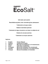
Salt Pool Chlorination System
Models: DES2-15E, DES2-15EL, DES2-25E,
DES2-25EL & DES2-35E
Installation and Operating
Instructions
The installation of this product should be carried out by a person knowledgeable
in swimming pool plumbing requirements following the installation instructions
provided in this manual.
WARNING: Failure to follow these instructions and comply with all applicable
codes may cause serious bodily injury and/or property damage.
Please pass these instructions on to the operator of this equipment.
EcoSalt
®
2
7 LANGUAGES
English, Deutsch, Italiano,
Nederlands, Português,
Español & Français
ENGLISH

2
EcoSalt
®
2
Congratulations! You are now the proud owner of a new EcoSalt2. Please read all information in this manual
carefully before installing or operating your EcoSalt2.
Contents:
PACKING LIST ..................................................................................................................................................3
IMPORTANT SAFETY INSTRUCTIONS ...........................................................................................................4
COMMON TERMS ............................................................................................................................................6
INSTALLING THE EcoSalt2 ..............................................................................................................................6
CONNECTING THE IN-LINE ELECTROLYTIC CELL TO THE POWER SUPPLY ...........................................7
CONNECTING THE FLOW SWITCH TO THE CELL HOUSING ......................................................................7
PRE-START UP PROCEDURE .........................................................................................................................8
OPERATION OF YOUR EcoSalt2 .....................................................................................................................8
CONTROL PANEL ............................................................................................................................................. 9
INITIAL START-UP ............................................................................................................................................9
TYPICAL (EVERYDAY) START-UP .................................................................................................................12
EcoSalt2 FEATURES ......................................................................................................................................13
MAINTENANCE OF POWER SUPPLY ...........................................................................................................25
MAINTENANCE OF THE IN-LINE ELECTROLYTIC CELL .............................................................................25
DAY TO DAY OPERATION ..............................................................................................................................26
CHLORINE PRODUCTION .............................................................................................................................28
GENERAL INFORMATION ..............................................................................................................................29
TROUBLE SHOOTING ...................................................................................................................................29
SPARE PARTS ................................................................................................................................................30
ENGLISH

3
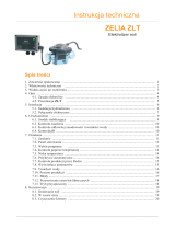
PACKING LIST
Included with your EcoSalt2 are the following items, please check the contents of the box carefully prior to
attempting to install the system:
a. 1 x Power supply with cell lead;
b. 1 x Flow switch;
c. 1 x In-line electrolytic cell & housing;
d. 1 x Cell blanking cap & o-ring;
e. 2 x Barrel unions including nut, tail & o-ring;
f. 2 x Reducing bushes;
g. 1 x Earth bolt assembly;
h. 1 x Quick reference guide;
i. 1 x Power lead; and
j. 1 x Mounting screws & plugs pack
Models | Modelle | Modelli | Modellen | Modelos | Modèles |:
DES2-15E, DES2-15EL, DES2-25E, DES2-25EL, DES2-35E
Quick Reference Guide | Salt Pool Chlorination System
Kurzanleitung | Desinfektionssystem unter verwendung des salzwassers
Guida rapida | Trattamento ad acqua salata
Korte handleiding | Badzout zwembad systemen
Guia rápido de referências | Tratamento da água da piscina com base na adição de sal
Guia de referencia rapida | Sistema de sal para piscinas
Guide de référence rapide | Electrolyseur de piscine au sel
EcoSalt
®
2
www.bit.ly/EcoSalt2
Mo
d
e
l
s
|
Mo
d
e
l
l
e
|
Mod
e
l
l
i
|
Mo
d
e
l
l
e
n
|
Mo
d
e
l
o
s
|
M
o
d
è
l
e
s
|
:
D
E
S2
-
1
5
E
L
&
D
E
S2
-
2
5
E
Q
u
i
ck
Refe
r
en
ce
G
u
i
d
e
|
S
al
t
P
ool
C
h
l
o
r
i
n
at
i
on
S
y
s
t
em
Ku
rz
an
l
ei
tu
n
g
|
Desi
n
f
ek
ti
on
ssy
st
e
m
u
n
ter
v
erw
en
d
u
n
g
d
es
sal
z
w
assers
G
u
i
d
a
r
ap
i
d
a
|
T
r
at
tamen
t
o
ad
acq
u
a
s
al
ata
K
or
t
e
h
an
d
l
ei
d
i
n
g
|
Bad
z
ou
t
z
wemb
ad
s
y
s
t
e
m
en
G
u
ia
r
á
p
id
o
d
e
r
e
fe
r
ê
n
c
ia
s
|
T
r
a
t
a
m
e
n
t
o
d
a
á
g
u
a
d
a
p
is
c
in
a
c
o
m
b
a
se
n
a
a
d
iç
ã
o
d
e
sa
l
G
u
i
a
d
e
r
e
fer
en
ci
a
r
ap
i
d
a
|
S
i
s
t
em
a
d
e
s
al
p
ar
a
p
i
s
ci
n
as
G
u
i
d
e
d
e
r
éfér
en
ce
r
ap
i
d
e
|
E
l
ect
r
ol
y
s
eu
r
d
e
p
i
s
ci
n
e
au
s
el
EcoSal
t
®
2
w
w
w
.
bi
t
.
l
y
/
E
c
o
Sa
l
t2
2 x 2 x
2 x 2 x
www.bit.ly/EcoSalt2
Remote/Auto Control
Firefighter Pump
Models: 5190HRS & 5290HRS
Mark II
INSTALLATION AND
OPERATING INSTRUCTIONS
Please pass these instructions on to the operator of this equipment.
a
g h i j
b c d e f
NOTE: Your EcoSalt2 is not intended for use by young children or inrm persons
without supervision. Please ensure that young children are supervised to ensure that
they do not play with the EcoSalt2 System.
Power connections and wiring must be carried out by an authorised electrician.
ENGLISH
ENGLISH

4
Diagram A
CORRECT OPERATION
WITH A PUMP RUNNING
Diagram B
INCORRECT OPERATION
WITH A PUMP RUNNING
ü
û
• Always check for the latest versions of installation and
operation instructions that support these products.
Simply scan this QR code, or go to: www.bit.ly/EcoSalt2
IMPORTANT SAFETY INSTRUCTIONS
• To minimise the risk of gas build-up in the cell housing, you must ensure there is sufcient
water ow through the cell when the unit is on and producing chlorine.
• It is essential that your pool pump circulates sufcient water through the cell housing to
completely ll the cell housing with water during the chlorination process.
• Periodically check the paddle of the safety ow switch to ensure it is free to move back and
forth and that the lock nut is done up hand tight.
ENGLISH

5
IMPORTANT INFORMATION
ABOUT YOUR EcoSalt2
FACTORS THAT WILL IMPROVE THE PERFORMANCE & LIFE OF YOUR EcoSalt2.
PLEASE READ THIS BEFORE OPERATING YOUR CHLORINATOR
POOL BUILDERS:
Please cover this information with your customer during the new pool “Handover Session”.
Chlorinators are a valuable piece of pool equipment and must be cared for to get the best
performance and life span. There are THREE main factors that will damage your EcoSalt2
and reduce the life of the product. Please monitor the following factors in accordance with your
installation & operating instructions.
1. MAINTAIN RECOMMENDED SALT LEVELS
RECOMMENDED OPERATING RANGE: (see page 27)
• Run your EcoSalt2 at the salt levels stated within this document and on the product to
ensure optimum performance and cell life;
• Operating the EcoSalt2 at low salt levels will damage the cell and reduce its life;
•ThecontrolpaneldisplaysaashingredLEDindicatorwarningwhenthesaltlevels
are low;
• If no action is taken to rectify the salt levels, damage to the cell may result which will
not be covered under warranty.
2. MONITOR & MAINTAIN YOUR EcoSalt2 IN-LINE CELL
EcoSalt2 has a “reverse polarity” in-line cell.
• To keep your EcoSalt2 in the best possible condition, regular monitoring of the cell is
recommended. The cell is in the clear plastic housing and contains the Titanium plates.
• During the chlorination process a white powdery Calcium scale may naturally build up
on the Titanium plates in the cell. Monitor the cell to prevent excessive scale build up.
Excessive scale build-up will cause damage to your cell, and dramatically reduce its
efciencyandlifespan.
• The control panel displays a red LED indicator warning that indicates that the cell may
require cleaning.
• If Calcium scale builds up please clean the cell, following the cleaning instructions provided
on page 26.
• NEVER: Use concentrated acid to clean your cell.
• NEVER: Leave cell in cleaning solution for extended periods of time.
• NEVER: Use metal implements, scourers, or brushes to clean the cell.
3. BALANCED POOL WATER CHEMISTRY
• Correct salt levels MUST be maintained (see page 27) for optimum performance and lifespan.
• Calcium Hardness levels MUST be kept to ideal ranges of 200 - 275ppm (for Concrete
and Tiled Pools) and 100 - 225ppm (for other surfaces) to prevent excessive scale build up
and damage to equipment.
• pH levels MUST be kept to ideal levels to prevent damage to equipment and pool surfaces
and to obtain optimum chlorination effectiveness.
• Total Alkalinity and Stabiliser levels must also be kept in an ideal range.
Note: Please refer to the POOL WATER CHEMISTRY chart on page 29 for more information.
ENGLISH
ENGLISH

6
COMMON TERMS
Algae Microscopic forms of plant life which enter the pool by rain, wind and dust. There are
numerous varieties – some are free floating whilst others grow on walls and in cracks
and come in different colours. Some are more resistant to chemical treatment than others.
Bacteria The germs that contaminate your pool. Introduced by swimmers, dust, rain storms
and other elements.
Balanced water The correct ratio of mineral content and pH level that prevents pool water from being
corrosive or scale forming.
Chloramines Compounds formed when chlorine combines with nitrogen from urine, perspiration, etc.
Chloramines cause eye and skin irritation, as well as unpleasant odours.
Chlorine demand The chlorine required to destroy germs, algae and other contaminants in the pool.
Chlorine residual The amount of chlorine remaining after chlorine demand has been satisfied.
This is the reading obtained with your test kit.
Cyanuric acid Also known as stabiliser or conditioner. It reduces dissipation of chlorine by direct
sunlight.
Liquid acid Chemical used to reduce the pH and total alkalinity in the pool water, and for cleaning
Sanitiser cell.
ppm An abbreviation for Parts Per Million the accepted measurement of chemical
concentration in swimming pool water. 1 ppm = 1 mg/L.
INSTALLING THE EcoSalt2
INSTALLING THE POWER SUPPLY
Select a convenient well-ventilated location within one metre of filter equipment and mount the power supply
vertically onto a wall, or post at least as wide as the EcoSalt2 power supply itself. Davey recommends that
the power supply shall not be located within 3 meters of the pool water. Plug pump and chlorinator power
supply into a suitable weatherproof power outlet/controller. Where applicable, some model variants have a
3-pin socket on the underside of the power supply, provide pump power. The unit must be kept away from
acid and other chemical storage areas. Acid and chemical vapours will corrode the electronics inside the unit.
It must also be kept away from heat sources. Good ventilation is necessary for correct operation.
Two self-tapping screws and wall plugs have been provided for fast and simple installation.
Use a 6mm masonry drill bit when fitting Power Supply to a brick or concrete wall. When mounting to a post
drill pilot holes and fit screws provided. Holes should be level and 164mm apart. Once screws are in position
simply hang EcoSalt2 power supply via mounts on back of Unit.
Return to pool line
Suction Line
FILTER
PUMP
ACCESSORIES
230V POWER SUPPLY
ENGLISH

7
INSTALLING THE CELL
The EcoSalt2 cell should always by the last appliance in your system. Ensure the cell is installed after
pumps, filters and any heating appliances. To achieve best efficiency, the EcoSalt2 cell should be installed
such that turbulent water is limited as much as possible. Do not install a 90° elbow closer that 200mm from
the cell’s inlet barrel union. Isolation valves used where equipment is located below pool water level, should
also be installed no closer than 200mm from inlet barrel union. This will assist laminar flow.
CONNECTING THE IN-LINE ELECTROLYTIC CELL TO THE POWER SUPPLY
The EcoSalt2 salt water sanitiser uses a reverse polarity in-line electrolytic cell for low maintenance
operation. The EcoSalt2 power supply is fitted with a flexible lead terminated with the cell connectors
built into a plastic moulding. The three in-line connectors are not “polarity sensitive”. Depending on the
installation, it may be necessary to support the cell housing underneath, by hand.
NOTE: The EcoSalt2 cell is supplied with a paddle type flow switch, which is to be installed on the
cell as shown in the diagram on page 4 and connected to the cell lead via the connector on the end
of the cable.
IMPORTANT: The ow switch must be mounted with the highlighted arrow on side of
the switch pointing in the direction of ow.
CONNECTING THE FLOW SWITCH TO THE CELL HOUSING
Ensure that the flow switch is installed into the cell housing.
Ensure the flow switch direction is correct (see page 4)
Fitted
ENGLISH
ENGLISH

PRE-START UP PROCEDURE
Before operating your EcoSalt2 salt pool chlorination system, please ensure the following quantity of pool
salt has been added to your pool.
• POOL SALT:
To raise salt
concentration by
Salt required
ppm %
30,000L 40,000L 50,000L 60,000L 70,000L 80,000L 90,000L 100,000L
kg lbs kg lbs kg lbs kg lbs kg lbs kg lbs kg lbs kg lbs
1,000 0.1 30 66 40 88 50 110 60 132 70 154 80 176 90 198 100 220
2,000 0.2 60 132 80 176 100 220 120 265 140 309 160 353 180 397 200 441
3,000 0.3 90 198 120 265 150 331 180 397 210 463 240 529 270 595 300 661
4,000 0.4 120 265 160 353 200 441 240 529 280 617 320 705 360 794 400 882
5,000 0.5 150 331 200 441 250 551 300 661 350 772 400 882 450 992 500 1,102
6,000 0.6 180 397 240 529 300 661 360 794 420 926 480 1,058 540 1,190 600 1,323
• CHLORINE: For a new pool installation that has not been chlorinated, add sufficient Chlorine (liquid or
granular) to achieve a reading of 3 ppm (with a suitable test kit). Alternatively, run the EcoSalt2 salt pool
chlorination system continuously on BOOST MODE, for approximately 24 hours, or until a reading of 3 ppm
is reached.
• STABILISER: It is essential that pool stabiliser be added and maintained at the rate of 25 - 50 ppm at
all times (FOR OUTDOOR POOLS ONLY). For ORP controlled systems the stabiliser level should be
maintained between 15-25ppm.
• (Refer Day to Day Operation page 27 for further information).
OPERATION OF YOUR EcoSalt2
CHLORINE OUTPUT is expressed as a percentage. Set the EcoSalt2 to the percentage output required
and the unit will automatically adjust the cell output to the set level. The EcoSalt2 is fitted with an electronic
control and warning system. This regulates the output of the EcoSalt2 to the pre-set maximum and changes
cell polarity as indicated by the + or – on the digital display. The polarity will alternate over a number of
hours of chlorination time, not necessarily pump-run hours. The warning system consists of one Operation
LED which will glow Green to indicate normal operation, or RED to indicate user attention required, see
troubleshooting on page 21.
8
ENGLISH

9
CONTROL PANEL
LAYOUT
100% – 09:29 AM
ON
Manual on/off
Menu up/down
Menu/setting select
Menu/setting cancel (go back)
Power indicator
(lit when EcoSalt2 on)
Alarm indicator
(asheswhenalarmactive)
Time out
(whenever device is left for 30 seconds
without input from user, settings are saved,
and home screen displayed)
INITIAL START-UP
Once the salt level in the pool is correct the unit may be switched on.
Note: Once the unit starts there is a short time delay until the cell operates to ensure the filtration
system is primed with water.
• The first time the EcoSalt2 is turned on, the following screen is shown on start-up:
DAVEY
V1.2.1 EU 15L
> This screen shows the version of software (ie v1.2.1 shown) and your model of EcoSalt2 (ie EU 15L
shown, meaning DES2-15EL).
• The display then automatically reverts to the following screen:
ENGLISH
ENGLISH

10
3. LANGUAGE
ENGLISH
> This screen shows the language menu and the current language setting (ie English shown);
> The language setting can be changed by pressing the
menu up/down buttons to scroll through
available languages;
> Press
menu/setting select once your preferred language is displayed;
> If a mistake is made, the setting can be changed later.
• The display then automatically reverts to the following screen:
4. TIME FORMAT
12HR
> This screen shows the time format menu and the current time format (ie 12HR shown);
> The time format can be changed by pressing the
menu up/down buttons to toggle between 12HR
and 24HR formats;
> Press
menu/setting select once your preferred time format is displayed;
> If a mistake is made, the setting can be changed later.
• The display then automatically reverts to the following screen:
1. CLOCK
07:34 PM
> This screen shows the clock’s current time (ie 07:34PM shown);
> Initially the clock hours will be flashing;
> The clock hours can be changed by pressing the
menu up/down buttons to scroll to your chosen time;
ENGLISH

11
> Press
menu/setting select once your preferred clock hour is displayed;
> If a mistake is made, the setting can be changed later.
> Next the clock minutes will be flashing;
> The clock minutes can be changed by pressing the
menu up/down buttons to scroll to your chosen time;
> Press
menu/setting select once your preferred clock minutes is displayed;
> If a mistake is made, the setting can be changed later.
> Next the clock AM/PM will be flashing;
> The clock AM/PM can be changed by pressing the
menu up/down buttons to toggle between
AM and PM;
> Press
menu/setting select once your preferred clock AM/PM is displayed;
> If a mistake is made, the setting can be changed later.
• The display then automatically reverts to the following screen:
2. DATE
01 JAN 2000
> This screen shows the date format menu and the current date (ie 01 JAN 2000 shown);
> Initially the date day will be flashing;
> The date day can be changed by pressing the
menu up/down buttons to scroll to your
chosen date day;
> Press
menu/setting select once your preferred date day is displayed;
> If a mistake is made, the setting can be changed later.
> Next the date month will be flashing;
> The date month can be changed by pressing the
menu up/down buttons to scroll to your chosen
date month;
> Press
menu/setting select once your preferred date month is displayed;
> If a mistake is made, the setting can be changed later.
> Next the date year will be flashing;
> The date year can be changed by pressing the
menu up/down buttons to scroll to your chosen
date year;
> Press
menu/setting select once your preferred date year is displayed;
> If a mistake is made, the setting can be changed later.
• The display then automatically reverts to the HOME screen:
ENGLISH
ENGLISH

12
100% – 09:29 AM
ON
> This screen shows the:
■ current chlorine output setting (ie 100% shown);
■ current time setting;
■ current power status (ie ON shown).
TYPICAL (EVERYDAY) START-UP
Note: Once the unit starts there is a short time delay until the cell operates to ensure the filtration
system is primed with water.
• Every time the EcoSalt2 is turned on, the following screen is shown on start-up:
DAVEY
V1.2.1 EU 15L
• The display then automatically reverts to the HOME screen:
100% – 09:29 AM
ON
> This screen shows the:
■ current chlorine output setting (ie 100% shown);
■ current time setting;
■ current power status (ie ON shown).
ENGLISH

13
EcoSalt2 FEATURES
CONTROLLING CHLORINE OUTPUT
65% – 09:35 AM
0N
The CHLORINE OUTPUT controls the time that the cell is producing chlorine, as a percentage of total time
that the EcoSalt2 is on. If the EcoSalt2 cell is producing, it is producing at 100%, unless otherwise altered
(see sections WINTER MODE, or SPA MODE). The cell run time is referred to as “cell duty cycle”.
For example:
• If the EcoSalt2 is on for 8 hours per day, and the CHLORINE OUTPUT is set to 50%: the EcoSalt2 cell
duty cycle is only 4 hours, of that day;
• If the EcoSalt2 is on for 8 hours per day, and the CHLORINE OUTPUT is set to 25%: the EcoSalt2 cell
duty cycle is only 2 hours, of that day.
To adjust the CHLORINE OUTPUT:
70% – 09:35 AM
CHLORINE OUTPUT
> Press the menu up/down buttons to scroll to your chosen CHLORINE OUTPUT;
> The setting will change the cell duty cycle by 5% increments;
> Press
menu/setting select once your preferred CHLORINE OUTPUT is displayed;
> This will then take you back to the HOME screen.
ACTIVATING COVER MODE
A pool’s exposure to UV contributes significantly to the pool’s total chlorine demand. Ie the amount of
chlorine the pool uses. Excessive amounts of chlorine in a pool with a cover on, can significantly shorten the
life expectancy of the pool cover, if left for long periods of time (eg weeks). Turning on the COVER MODE
reduces the cell duty cycle by 80% of its current setting.
For example:
• If the EcoSalt2 is on for 8 hours per day, the CHLORINE OUTPUT is set to 50%, but the COVER MODE is
on: the EcoSalt2 cell duty cycle is only 48 minutes, of that day;
• If the EcoSalt2 is on for 8 hours per day, the CHLORINE OUTPUT is set to 25%, but the COVER MODE is
on: the EcoSalt2 cell duty cycle is only 24 minutes, of that day.
ENGLISH
ENGLISH

14
To turn on COVER MODE:
70% – 09:35 AM
CHLORINE OUTPUT
> From the HOME screen, press menu/setting select.
> The display will show this screen:
MODE
1. COVER
> From this screen, press menu/setting select to enter cover mode menu;
> The display will show the current COVER MODE setting (ie COVER MODE off shown):
1. COVER
OFF
> Press the menu up/down buttons to toggle between COVER MODE on and off;
> Press
menu/setting select once your preferred COVER MODE is displayed;
> This will then take you back to the first setting menu;
> If the EcoSalt2 is left untouched for ~ 30 seconds, or the
menu/setting cancel (go back) button is
pushed, the display reverts to the HOME screen.
ENGLISH

15
COVER MODE can also be triggered remotely
by an automated pool cover controller. By
closing the terminal block contacts on the
rear of the power supply, the EcoSalt2 will
remotely switch to COVER MODE. This
can be overridden by user intervention, by
following the steps explained previously.
ACTIVATING BOOST MODE
Should the pool experience a heavy bather load, debris/contamination, or extreme warm weather, there may
be a need to super-chlorinate the pool. Turning on the BOOST MODE increases the cell duty cycle to 100%
and overrides the cell current (output) to 100% for a period of 24 hours.
To turn on BOOST MODE:
70% – 09:35 AM
CHLORINE OUTPUT
> From the HOME screen, press menu/setting select.
> The display will show this screen:
ENGLISH
ENGLISH

16
MODE
1. COVER
> Press the menu up/down buttons to toggle between BOOST MODE;
MODE
2. BOOST
> Press menu/setting select;
2. BOOST
OFF
> The display will show the current BOOST MODE setting (ie BOOST MODE off shown);
> Press the
menu up/down buttons to toggle between BOOST MODE on and off;
ENGLISH

17
2. BOOST
ON
> Press menu/setting select once your preferred BOOST MODE is displayed;
> This will then take you back to the first setting menu;
> If the EcoSalt2 is left untouched for ~ 30 seconds, or the
menu/setting cancel (go back) button is
pushed, the display reverts to the HOME screen.
50% – 09:40 AM
BOOST
> The HOME screen will continue to show the cell duty cycle percentage, however the reference to “ON” has
been notably replaced by the reference to “BOOST”. This will remain for the 24 hour period;
> It is possible to alter the cell duty cycle during a 24-hour boost and the display percentage on the HOME
screen changes as expected. This could be handy if the setting needs altering for the next day, once the
BOOST MODE is finished;
> It should be noted though, BOOST MODE overrides every other setting. During the 24 hour period while
is BOOST MODE is active, the cell current is 100% output, and duty cycle is overridden to 100%. This is
regardless of the display on the screen.
ACTIVATING SPA MODE
The EcoSalt2 system is compatible with large swimming pool applications as well as much smaller spa
applications. Turning on the SPA MODE reduces the cell duty cycle by 80% of its current setting.
For example:
• If the EcoSalt2 is on for 10 hours per day, the CHLORINE OUTPUT is set to 50%, but the SPA MODE is
on: the EcoSalt2 cell duty cycle is only 1 hour, of that day;
• If the EcoSalt2 is on for 10 hours per day, the CHLORINE OUTPUT is set to 25%, but the spa MODE is
on: the EcoSalt2 cell duty cycle is only 30 minutes, of that day.
ENGLISH
ENGLISH

18
To turn on SPA MODE:
70% – 09:35 AM
CHLORINE OUTPUT
> From the HOME screen, press menu/setting select.
> The display will show this screen:
MODE
1. COVER
> Press the menu up/down buttons to scroll to SPA MODE;
MODE
3. SPA
> From this screen, press menu/setting select to enter SPA MODE menu;
> The display will show the current SPA MODE setting (ie SPA MODE off shown):
ENGLISH

19
3. SPA
OFF
> Press menu up/down buttons to toggle between SPA MODE on and off;
> Press
menu/setting select once your preferred SPA MODE is displayed;
> This will then take you back to the first setting menu;
> If the EcoSalt2 is left untouched for ~ 30 seconds, or the
menu/setting cancel (go back) button is
pushed, the display reverts to the HOME screen.
ACTIVATING SPA MODE AND COVER MODE SIMULTANEOUSLY
Should it be necessary to run SPA MODE and COVER MODE simultaneously, the cell duty cycle is only
reduced by 80% That is, the cell duty cycle isn’t reduced by 80%, followed by a further 80%. The HOME
screen display will toggle between showing COVER and SPA.
ACTIVATING WINTER MODE
A pool’s exposure to UV contributes significantly to the pool’s total chlorine demand. Ie the amount of
chlorine the pool uses. Bather load is also a significant contributor to the pool’s total chlorine demand. In
winter, the pool’s chlorine demand is typically far less. Unless otherwise altered, if the cell is producing
chlorine, it is producing at 100% current (output). WINTER MODE reduces the cell’s current (output) to 85%.
For example:
• If the EcoSalt2 is on for 10 hours per day, the CHLORINE OUTPUT is set to 100%, the WINTER MODE is
off: the EcoSalt2 cell duty cycle is 10 hours. The cell current will be operating at 100% capacity;
• If the EcoSalt2 is on for 10 hours per day, the CHLORINE OUTPUT is set to 100%, but the WINTER
MODE is on: while the EcoSalt2 cell duty cycle is still 10 hours, the cell current will only be operating at
85% capacity.
To turn on WINTER MODE:
70% – 09:35 AM
CHLORINE OUTPUT
> From the HOME screen, press menu/setting select.
ENGLISH
ENGLISH

20
> The display will show this screen:
MODE
1. COVER
> Press the menu up/down buttons to scroll to WINTER MODE;
MODE
4. WINTER
> From this screen, press menu/setting select to enter WINTER MODE menu;
> The display will show the current WINTER MODE setting (ie WINTER MODE off shown):
4. WINTER
OFF
> Press menu up/down buttons to toggle between WINTER MODE on and off;
> Press
menu/setting select once your preferred WINTER MODE is displayed;
> This will then take you back to the first setting menu;
> If the EcoSalt2 is left untouched for ~ 30 seconds, or the
menu/setting cancel (go back) button is
pushed, the display reverts to the HOME screen.
ENGLISH
/