
ENGLISH
Contrast Scanner
with laser light
Operating Instructions
Safety Specifications
‡ Read the operating instructions before starting operation.
‡ Connection, assembly, and settings only by competent technicians.
‡ Protect the device against moisture and soiling when operating.
‡ No safety component in accordance with EU machine guidelines.
Proper Use
The KT 5L contrast scanner is an optoelectronic sensor and is
used for optical, non-contact detection of contrast marks.
Starting Operation
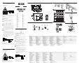
1
Equipment plug horizontally (H) and vertically (V) adjustable.
Connect and secure cable receptacle tension-free.
The following apply for connection in B: brn=brown,
blu=blue, blk=black, wht=white.
2
Outputs: Q
PNP
or Q
NPN
(corresponding to type label, see
below).
Q
A
: Analog output; output current proportional to received
light.
Connect the scanner according to the B connection chart.
3
Timing element (corresponding to type label, see below):
Release delay see 3a; One shot, see 3b.
Attention! Do not replace the lens with a dummy screw.
4
Mount the sensor with mounting holes at the place (e.g.,
deflection roller) where the test object has the least horizontal
and vertical movement. Pay attention to the scanning range when
doing this (see the technical data at the end of these operating
instructions and the chart: x=scanning range; y= relative
sensitivity). Align the horizontal and vertical movements of the
test object using correspondingly long markings. Make sure that
sensor movement does not influence the scanning distance.
5
In the case of objects with reflective or shiny surface, tilt sensor
by 10
o
to 15
o
relative to surface. Connect cables. Connect
photoelectric switch to operating voltage (see type label).
6
Switching threshold setting.
Operating panel
A=dark; B=light; C=light/dark selector; D=status indicator;
E=indicator for direction of rotation; F=switching threshold
adjuster. Set the switching threshold in the middle position
between background and mark; the signal reserve is set to
maximum. Setting for a dark mark on a light background. Set the
light/dark selector to dark. Place the mark in the light spot
Turn the switching threshold adjuster until the status indicator
lights. Place the background in the light spot. Continue to turn the
switching threhold adjuster until the status indicator lights; count
the number of rotations. Turn the switching threshold adjuster
back by half of the number of rotations.
KT 5L-P_ _ _4_ onlKT 5L-P_ _ _4_ onl
KT 5L-P_ _ _4_ onlKT 5L-P_ _ _4_ onl
KT 5L-P_ _ _4_ onl
y:y:
y:y:
y:
The status indicator only lights 20 ms.
Maintenance
SICK contrast scanners do not require any maintenance. We
recommend that you clean the optical interfaces and check the
screw connections and plug-in connections at regular intervals.
DEUTSCH
Kontrasttaster
mit Laserlicht
Betriebsanleitung
Sicherheitshinweise
‡ Vor der Inbetriebnahme die Betriebsanleitung lesen.
‡ Anschluss, Montage und Einstellung nur durch Fachpersonal.
‡ Gerät bei Inbetriebnahme vor Feuchte und Verunreinigung
schützen.
‡ Kein Sicherheitsbauteil gemäß EU-Maschinenrichtlinie.
A 1 4
Bestimmungsgemäße Verwendung
Der Kontrasttaster KT 5L ist ein opto-elektronischer Sensor
und wird zum optischen, berührungslosen Erfassen von
Kontrastmarken eingesetzt.
Inbetriebnahme
1
Gerätestecker nach horizontal (H) und vertikal (V) schwenkbar.
Leitungsdose spannungsfrei aufstecken und festschrauben.
Für Anschluss in B gilt: brn=braun, blu=blau, blk=schwarz,
wht=weiß
2
Ausgänge: Q
PNP
oder Q
NPN
(entspr. Typenschlüssel, s.u.)
Q
A
: Analogausgang, Ausgangsstrom propotional Lichtempfang.
Taster laut Anschlussschema B anschließen.
3
Zeitglied (entspr. Typenschlüssel, s.u.): Abfallverzögerung s. 3a;
One shot, s. 3b. Achtung: Objektiv nicht gegen Blind-
verschraubung tauschen.
4
Sensor mit Befestigungsbohrungen an Stelle (Z. B. Umlenkrolle)
montieren, an der das Prüfobjekt die geringsten Seiten- und
Höhenbewegungen ausführ t. Dabei Tastweite beachten (s.
technische Daten am Ende dieser Betriebsanleitung und siehe
Diagramm, x=Tastweite, y=relative Empfindlichkeit).
Seiten- und Höhenbewegungen des Prüfobjektes durch
entsprechend lange Markierungen ausgleichen.
Bewegungen des Sensors mit Tastweiteneinfluss ausschließen.
5
Bei spiegelnden oder glänzenden Objektoberflächen Sensor
um 10
o
bis 15
o
zur Materialoberfläche neigen.
Leitungen anschließen. Sensor an Betriebsspannung legen (s.
Typenaufdruck).
6
Einstellung Schaltschwelle:
Bedienfeld: A=dunkelschaltend; B=hellschaltend; C=Hell-Dunkel-
Umschalter; D=Funktionsanzeige; E=Drehrichtungsanzeige;
F=Schaltschwelleneinsteller.
Schaltschwelle in Mittelstellung zwischen Untergrund und Marke
einstellen: Signalreserve wird maximal. Einstellung für dunkle
Marke auf hellem Grund: Hell-Dunkel-Umschalter auf
dunkelschaltend stellen. Marke in Lichtfleck bringen.
Schaltschwelleneinsteller drehen, bis Funktionsanzeige
aufleuchtet. Untergrund in den Lichtfleck bringen.
Schaltschwelleneinsteller weiterdrehen, bis Funktionsanzeige
aufleuchtet; Umdrehungen zählen. Schaltschwelleneinsteller um
die Hälfte der Umdrehungen zurückdrehen.
Nur KT 5L-P_ _ _4_ :Nur KT 5L-P_ _ _4_ :
Nur KT 5L-P_ _ _4_ :Nur KT 5L-P_ _ _4_ :
Nur KT 5L-P_ _ _4_ :
Funktionsanzeige leuchtet nur 20 ms auf.
Wartung
SICK-Kontrasttaster sind wartungsfrei. Wir empfehlen, in
regelmäßigen Abständen
- die optischen Grenzflächen zu reinigen,
- Verschraubungen und Steckverbindungen zu überprüfen.
B
2
3
6
5
We reserve the right to make changes without prior notification
Änderungen vorbehalten
Sous réserve de modifications
Reservam-se alteraç ões
Ret til ændringer forbeholdes
Con riserva di modifiche
Wijzigingen voorbehouden
Reservado el derecho a introducir modificaciones
KT 5L
8 007 645.0496 HJS KE
SICK AG
Schiess-Straße 56
D-40549 Düsseldorf
02 11 53 01-0
Fax: 02 11 53 01-1 00
www.sick.de
Australia
Erwin Sick Optic-Electronic Pty. Ltd.
Ivanhoe
03 94 97 41 00
Austria
SICK GmbH
2355 Wiener Neudorf
0 22 36 622 88-0
Belgium/Luxembourg
Sick nv/sa
Asse (Relegem)
02 4 66 55 66
Brazil
SICK Indústria & Comércio Ltda.
São Paulo
011 55 61 26 83
China/Hong Kong
SICK Optic-Electronic Co., Ltd.
Kowloon
20 27 63 69 66
Czech Republic
SICK spol. sro.
Praha 5-Radotin
02 578 10 561
Denmark
SICK A/S
Birkerød
45 82 64 00
Finland
SICK Optic-Electronic Oy
Helsinki
09 7 28 85 00
France
SICK
Marne la Vallée
1 64 62 35 00
Great Britain
Erwin Sick Ltd.
St. Albans
0 17 27 83 11 21
Italy
SICK S.p.A.
Cernusco sul Naviglio -MI-
02 92 14 20 62
Japan
SICK Optic-Electronic K.K.
Tokyo
03 33 58-13 41
Netherlands
SICK B. V.
AD Bilthoven
0 30 2 29 25 44
Norway
SICK AS
Gjettum
67 81 50-0
Poland
SICK Optic-Electronic Sp. z. o. o.
Warszawa
022 8 37 40 50
Singapore
SICK Optic-Electronic Pte. Ltd.
Singapore 387 383
65 7 44 37 32
Spain
SICK Optic-Electronic S. A.
Sant Just Desvern
93 4 80 31 00
Sweden
SICK AB
Vårby
08 6 80 64 50
Switzerland
SICK AG
Stans
041 6 19 29 39
Taiwan
SICK Optic-Electronic Co., Ltd.
Taipei
02 23 65 62 92
USA
SICK, Inc.
Bloomington, MN 55438
(952) 9 41-67 80
Seite wird geladen ...
-
 1
1
-
 2
2


in anderen Sprachen
- English: SICK SENSICK KT5L Operating instructions
- français: SICK SENSICK KT5L Mode d'emploi
- español: SICK SENSICK KT5L Instrucciones de operación
- italiano: SICK SENSICK KT5L Istruzioni per l'uso
- Nederlands: SICK SENSICK KT5L Handleiding
- português: SICK SENSICK KT5L Instruções de operação
- dansk: SICK SENSICK KT5L Betjeningsvejledning
Verwandte Artikel
-
SICK SENSICK NT8 Bedienungsanleitung
-
-
-
-
-
-
-
-
-