SICK SENSICK KT10W-2 Bedienungsanleitung
- Kategorie
- Komfortbeleuchtung
- Typ
- Bedienungsanleitung

Australia
Phone +61 3 9497 4100
Belgium/Luxembourg
Phone +32 (0)2 466 55 66
Brasil
Phone +55 11 3215-4900
Canada
Phone +1(952) 941-6780
Ceská Republika
Phone +420 2 57 91 18 50
China
Phone +852-2763 6966
Danmark
Phone +45 45 82 64 00
Deutschland
Phone +49 211 5301-301
España
Phone +34 93 480 31 00
France
Phone +33 1 64 62 35 00
Great Britain
Phone +44 (0)1727 831121
India
Phone +91–22–4033 8333
Israel
Phone +972-4-999-0590
Italia
Phone +39 02 27 43 41
Japan
Phone +81 (0)3 3358 1341
Magyarország
Phone +36 1 371 2680
Nederlands
Phone +31 (0)30 229 25 44
Österreich
Phone +43 (0)22 36 62 28 8-0
Norge
Phone +47 67 81 50 00
Polska
Phone +48 22 837 40 50
România
Phone +40 356 171 120
Russia
Phone +7 495 775 05 30
Schweiz
Phone +41 41 619 29 39
Singapore
Phone +65 6744 3732
Slovenija
Phone +386 (0)1-47 69 990
South Africa
Phone +27 11 472 3733
South Korea
Phone +82-2 786 6321/4
Suomi
Phone +358-9-25 15 800
Sverige
Phone +46 10 110 10 00
Taiwan
Phone +886 2 2375-6288
Türkiye
Phone +90 216 528 50 00
United Arab Emirates
Phone +971 4 8865 878
USA/México
Phone +1(952) 941-6780
BZ int37
Please find detailed addresses and additional representatives and agencies in
all major industrial nations at www.sick.com
Subject to change without notice
Irrtümer und Änderungen vorbehalten
Sujet à modifi cation sans préavis
Alterações poderão ser feitas sem prévio aviso
Med forbehold for ændringer og fejl
Contenuti soggetti a modifi che senza preavviso
Wijzigingen en correcties voorbehouden
Sujeto a cambio sin previo aviso
A
1
B
4
3
2
ON
ON
11
(0.43)
012
(0.47)
12.5
(0.49)
13
(0.51)
14
(0.55)
15
(0.59)
60
70
80
90
100
Relative sensitivity in %
Sensing distance in mm (inch)
M
V
ET
IA
AQ
SS
M
KT10W-2
----------------------------------------------------------- 8011064.VG83 0811 GO ----------------------------------------------------
---------------------------------------------------------------------------------------------------------------------------------------------------------------------------------------------------
5a
5b
5c
5d
5e
Q Bank Timer
SET
–
+
9 (0.35)
28
(1.10)
56 (2.20)
21
(0.83)
30.4
(1.20)
2.5
(0.10)
Ø 25.5
(1.00)
M5
M5
17
(0.67)
13
(0.51)
28 (1.10)
52 (2.05)
80 (3.15)
25 (0.98)
40 (1.57)
53 (2.09)
3
(0.12)
Sensing distance
10 mm (0.39 inch)
All dimensions in mm (inch)
SET
–
+
QBank Timer
4a
ENGLISH
ENGLISH
Contrast Scanner
with Teach-in
Operating Instructions
Safety Specifi cations
Read the operating instructions before starting operation.
Connection, assembly, and settings only by competent technicians.
Protect the device against moisture and soiling when operating.
No safety component in accordance with EU machine guidelines.
Proper Use
The KT10W-2 contrast scanner is an optoelectronic sensor and is used for
optical, non-contact detection of contrast marks.
Starting Operation
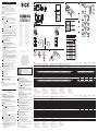
1 Equipment plug horizontally (H) and vertically (V) adjustable.
Connect and secure cable receptacle tension-free. The following apply
for connection in
B : brn = brown, blu = blue, blk = black, gra = gray,
wht = white.
AT: Blanking input to trigger sensor via external synchronization pulse.
ET: External teach input, to program an external input signal.
Outputs: Q
PNP
or Q
NPN
.
Connect the scanner according to the
B connection chart. Operation
signal light switches on (left LED of green bar chart).
2 Select the insertion position so that the light spot enters the marking
vertically.
3 Mount the sensor with mounting holes at the place (e.g., defl ection
roller) where the test object has the least horizontal and vertical
movement. Pay attention to the sensing range when doing this (see
the technical data at the end of these operating instructions and the
chart: x = sensing range; y = relative sensitivity).
Align the horizontal and vertical movements of the test object using
correspondingly long markings. Make sure that sensor movement does
not infl uence the sensing distance.
In the case of objects with refl ective or shiny surface, tilt sensor by 10°
to 15° relative to surface. Connect cables.
4 Setting for the switching threshold:
4a Dynamic teach-in (ex-works setting):
Depict the light spot on the original beside the mark.
Activate and hold teach-in signal via SET button (> 1 s).
Move the original with the mark at the sensing distance through the
light spot. Select material speed < 10 m/min.
Deactivate teach-in signal.
Diagram
4a shows an example: M = mark, SS = switching threshold,
V = original, ET = signal ET, IA = internal analogue signal, and AQ =
output Q.
Static 2-point teach-in:
Position light spot on the mark. Activate teach-in signal via SET button
(> 1 s) or TEACH (ET). Position the light spot on the original beside the
mark. Activate teach-in signal via SET button (> 1 s) or TEACH (ET).
Quality after teach-in:
Bar chart: Detection reliability. The more LEDs that light, the better
the teach-in. One LED lights: minimum contrast; 2 to 4 LEDs light: suf-
fi cient contrast. More than four LEDs light: high contract di erence.
If teach-in is not successful, the yellow LED (Q) blinks. Readjust the
sensor, clean it and/or check the application conditions.
5 Special setting:
“+” and “–” > 1 s: Access/exit special mode; “+” or “–”: navigate;
„SET“: confi rm/save.
5a Saving and retrieving templates (bank 1 to 5). Save: Select bank
RUN perform teach-in; Retrieve: Select bank RUN.
5b Switching threshold tracking and green bar display:
O = tracking o /bar display o ;
Example: Manual = readjustment per “+” and “–” keys;
Bar display displays signal strength. „+“ > 1 s to unlock, adjust thres-
hold with „+“ or „–“, confi rm with SET.
Automatic = automatic tracking/bar display, quality during RUN.
5c Select teach-in procedure:
Dynamic teach-in, static 2-point teach-in.
5d Switch-o delay (timer):
No o delay = delay inactive;
O delay 20 ms = delay 20 ms.
5e Output logic:
LO/DO = light-/dark-switching corresponding to teach-in sequence
DO = dark-switching, LO = light-switching.
6 Reset to ex-works setting (default):
press “+” and “–” > 1 s and then release;
press “+” and “–” > 5 s; the yellow status indicators blink 2x.
Maintenance
SICK sensors do not require any maintenance. We recommend that you
clean the external lens surfaces and check the screw connections and plug-
in connections at regular intervals.
DEUTSCH
DEUTSCH
Kontrastsensor
mit Teach-in
Betriebsanleitung
Sicherheitshinweise
Vor der Inbetriebnahme die Betriebsanleitung lesen.
Anschluss, Montage und Einstellung nur durch Fachpersonal.
Gerät bei Inbetriebnahme vor Feuchte und Verunreinigung schützen.
Kein Sicherheitsbauteil gemäß EU-Maschinenrichtlinie.
Bestimmungsgemäße Verwendung
Der Kontrastsensor KT10W-2 ist ein optoelektronischer Sensor und wird
zum optischen, berührungslosen Erfassen von Kontrastmarken eingesetzt.
Inbetriebnahme
1 Gerätestecker horizontal und vertikal schwenkbar.
Leitungsdose spannungsfrei aufstecken und festschrauben. Für
Anschluss in
B gilt: brn = braun, blu = blau, blk = schwarz, gra = grau,
wht = weiß.
AT: Austasteingang zur Triggerung des Sensors über einen externen
Synchronisationsimpuls.
ET: Eingang External Teach, zur Programmierung über ein externes
Eingabesignal.
Ausgänge: Q
PNP
oder Q
NPN
.
Sensor laut Anschlussschema
B anschließen. Betriebsanzeige (linke
LED der grünen Balkenanzeige) leuchtet.
2 Einbaulage so wählen, dass Lichtfl eck längs in die Markierung eintritt.
3 Sensor mit Befestigungsbohrungen an Stelle (z. B. Umlenkrolle)
montieren, an der das Prüfobjekt die geringsten Seiten- und Höhen-
bewegungen ausführt. Dabei Tastweite beachten (s. technische Daten
am Ende dieser Betriebsanleitung und siehe Diagramm, x = Tastweite,
y = relative Empfi ndlichkeit).
Seiten- und Höhenbewegungen des Prüfobjektes durch entsprechend
lange Markierungen ausgleichen. Bewegungen des Sensors mit
Tastweiteneinfl uss ausschließen.
Bei spiegelnden oder glänzenden Objektoberfl ächen Sensor um 10°
bis 15° zur Materialoberfl äche neigen.
Leitungen anschließen.
4 Einstellung Schaltschwelle:
4a Dynamisches Teach-in (Werkseinstellung):
Lichtfl eck auf der Vorlage vor der Marke abbilden.
Teach-in-Signal über SET-Knopf (> 1 s) oder ET aktivieren und halten.
Vorlage mit der Marke im Tastabstand durch Lichtfl eck bewegen.
Materialgeschwindigkeit < 10 m/min. wählen. Teach-in-Signal
deaktivieren.
Abbildung
4a zeigt ein Beispiel: M = Marke, SS = Schalt schwelle,
V = Vorlage, ET = Signal ET, IA = Internes Analogsignal, AQ = Aus-
gang Q.
Statisches 2-Punkt-Teach-in:
Lichtfl eck auf der Marke abbilden. Teach-in-Signal über SET-Knopf
(> 1 s) oder TEACH (ET) aktivieren. Lichtfl eck auf der Vorlage vor oder
nach der Marke abbilden. Teach-in-Signal über SET-Knopf oder TEACH
(ET) aktivieren.
Qualität nach Teach-in:
Balkenanzeige: Detektionssicherheit. Je mehr LEDs leuchten, desto
besser ist der Teach-in. Eine LED leuchtet: minimaler Kontrast, 2 bis 4
LEDs leuchten: ausreichend Kontrast.
Mehr als 4 LEDs leuchten: hoher Kontrast.
Bei nicht erfolgreichem Teach-in blinkt die gelbe LED (Q). Sensor neu
justieren, reinigen bzw. Einsatzbedingungen prüfen.
5 Spezialeinstellungen:
„+“ und „–“ > 1 s: Eintreten/Verlassen in/von Spezialmodus; „+“ oder
„–“: Navigieren; „SET“: Bestätigen/Speichern.
5a Speichern und Aufrufen von Vorlagen (Bank 1 bis 5)
Speichern: Bank auswählen RUN Teach-in durchführen,
Aufrufen: Bank auswählen RUN.
5b Schaltschwellen-Nachführung und grüne Balkenanzeige:
O = Nachführung aus/Balkenanzeige aus,
Manual = Nachstellung per „+“- und „–“-Taste,
Balkenanzeige zeigt Signalstärke an. „+“ > 1 s zum Entriegeln, mit „+“
oder „–“ Schaltschwelle anpassen, mit SET bestätigen.
Automatic = automatische Nachführung/Balkenanzeige, Qualität
während RUN.
5c Auswahl Teach-in-Verfahren:
Dynamisches Teach-in, Statisches 2-Punkt-Teach-in.
5d Ausschaltverzögerung (Timer):
No o delay = Verzögerung inaktiv,
O delay 20 ms = Verzögerung 20 ms.
5e Ausgangslogik:
LO/DO = Hell-/dunkelschaltend entsprechend Teach-in-Reihenfolge.
DO = dunkelschaltend, LO = hellschaltend.
6 Zurücksetzen in die Werkseinstellung (Default):
„+“ und „–“ > 1 s drücken und loslassen,
„+“- und „–“-Taste > 5 s drücken, die gelben Statusanzeigen blinken 2x.
Wartung
SICK-Kontrastsensoren sind wartungsfrei. Wir empfehlen, in regelmäßigen
Abständen
- die optischen Grenzfl ächen zu reinigen,
- Verschraubungen und Steckverbindungen zu überprüfen.
Automatic/detection security (Default)
OFF/OFF
Dynamic (Default)
Static, 2-point teach-in
OFF default (Default)
20 ms off delay
LO/DO default (Default)
> 1 s
> 1 s
Manual/signal strength
DO – always dark-switching
Bank 1 RUN (Default)
Bank 5
Bank 2
Bank 3
Bank 4
LO – always light-switching
Drift correction / Bar display
Job memory
Teach-in
Time stage
Output logic
RUN
> 1 s
RUN
> 1 s
RUN
> 1 s
RUN
> 1 s
RUN
> 1 s
KT10W -2P1115 -2N1115 -2P2115 -2N2115 -2N1115S04
Sensing distance from front edge of lens Tastweite ab Vorderkante Objektiv Distance de détection depuis le bord avant
Objectif
Raio de exploração a partir do bordo dianteiro
do objetiva
Tastvidde fra husets 10 ± 3 mm
Sensing distance from front edge of housing Tastweite ab Vorderkante Gehäuse Distance de détection depuis le bord avant
Boîtier
Raio de exploração a partir do bordo dianteiro
do gabinete
Tastvidde fra forkant 12,5 ± 3 mm
Light spot size Lichtfleckgröße Taille du spot lumineux Tamanho do ponto luminoso Lyspletstørrelse 0,8 x 4 mm 0,6 x 2 mm
Light spot orientation
1)
Lichtflecklage
1)
Orientation du spot
1)
Situação do ponto luminoso
1)
Lysplettens position
1)
llqql
Supply voltage V
S
2)
Versorgungsspannung U
V
2)
Tension d'alimentation U
V
2)
Tensão de força U
V
2)
Forsyningsspænding U
V
2)
10 … 30 V DC
Switching frequency
3)
Schaltfrequenz
3)
Fréquence de commutation
3)
Frequência de ligação
3)
Driftsfrekvens
3)
25 kHz
Response time Ansprechzeit Temps de réponse Tempo de reação Responstid 20 s
Jitter Jitter Jitter Jitter Jitter < 10 s
Switching output Schaltart Type de commutation Tipo de ligação Driftsart PNP NPN PNP NPN NPN
Switching output voltage Schaltausgang Sortie de commutation Saída de comutação Kontaktudgang
HIGH = U
V
– 2 V/LOW 0 V
HIGH = U
V
/LOW 2 V
HIGH = U
V
– 2 V/LOW 0 V
HIGH = U
V
/LOW 2 V HIGH = U
V
/LOW 2 V
Input, teach-in (ET) Eingang, Teach-in (ET) Entrée, apprentissage (ET) Entrada, Teach-in (ET) Indgang, teach-in (ET)
Teach: U = 10 V ... < U
V
Run: U < 2 V
Teach: U < 2 V
Run: U = 10 V ... < U
V
Teach: U = 10 V … < U
V
Run: U < 2 V
Teach: U < 2 V
Run: U = 10 V ... < U
V
Teach: U < 2 V
Run: U = 10 V ... < U
V
Input, blanking input (AT), blanked
4)
Eingang Austasteingang (AT), ausgetastet
4)
Entrée, entrée de masquage (AT), masquée
4)
Entrada sensora (AT), sensorizada
4)
Indgang slukkeindgang (AT), slukket
4)
U > 10 V ... < U
V
U < 2 V U > 10 V ... < U
V
U < 2 V –
Input, blanking input (AT), free-running
4)
Eingang Austasteingang (AT), freilaufend
4)
Entrée, entrée de masquage (AT), non asservie
4)
Entrada sensora (AT), de curso livre
4)
Indgang slukkeindgang (AT), friløbende
4)
U < 2 V U > 10 V ... < U
V
U < 2 V U > 10 V ... < U
V
–
Input, light/dark (L/D) Eingang, hell/dunkel (L/D) Entrée, clair/sombre (L/D) Entrada, claro/escuro (L/D) Indgang, lys/mørk (L/D) – L: U = U
V
, D: U = 0 V
Enclosure rating Schutzart Type de protection Tipo de proteção Tæthedsgrad IP 67
Ambient operating temperature Betriebsumgebungstemperatur Température ambiante Temperatura ambiente de operação Driftsomgivelsestemperatur –10 … +55 °C
Protection class
5)
Schutzklasse
5)
Classe de protection
5)
Classe de proteção
5)
Beskyttelsesklasse
5)
II
Circuit protection
6)
Schutzschaltungen
6)
Circuits de protection
6)
Circuitos protetores
6)
Beskyttelseskoblinger
6)
A, B, C
1)
l = vertical; q = horizontal.
2)
Limit values. Operation in short-circuit protec-
ted network max. 8 A.
3)
At light/dark ratio 1:1.
4)
T > 200 s.
5)
Reference voltage 50 V DC.
6)
A = V
S
connections reverse polarity protected
B = Outputs protected against short circuits
C = Interference pulse suppression.
1)
l = längs; q = quer.
2)
Grenzwerte. Betrieb in kurzschlussgeschütz tem
Netz max. 8 A.
3)
Bei Hell-Dunkel-Verhältnis 1:1.
4)
T > 200 s.
5)
Bemessungsspannung 50 V DC.
6)
A = U
V
-Anschlüsse verpolsicher
B = Ausgänge kurzschlussgeschützt
C = Störimpulsunterdrückung.
1)
l = longitudinalement; q = transversalement.
2)
Valeurs limites. Fonctionnement en réseau
protégé contre les courts-circuits max. 8 A.
3)
Pour un rapport clair/sombre de 1:1.
4)
T > 200 s.
5)
Tension de calcul 50 V DC.
6)
A = Raccordements U
V
protégés contre les
inversions de polarité
B = Sorties protégées contre les courts-circuits
C = Suppression des impulsions parasites.
1)
l = ao comprido; q = posição transversal.
2)
Valores limite. Funcionamento em rede com
protecção contra curto-circuito, máx. 8 A.
3)
Com relação de claro/escuro 1:1.
4)
T > 200 s.
5)
Tensão de dimensionamento 50 V DC.
6)
A = Conexões U
V
protegidas
B = Saídas protegidas contra curto circuito
C = Supressão de impulsos parasitas.
1)
l = på langs; q = på tværs.
2)
Grænseværdier. Drift i kortslutningssikret net,
maks. 8 A.
3)
Ved lys-/mørkeforhold på 1:1.
4)
T > 200 s.
5)
Dimensioneringsspænding 50 V DC.
6)
A = U
V
-tilslutninger med
B = Udgange kortslutningsresistent
C = Støjimpulsundertrykkelse.
KT10W -2P1115 -2N1115 -2P2115 -2N2115 -2N1115S04
Distanza di ricezione da spigolo anteriore
obiettivo
Tastafstand vanaf voorkant Objectief Amplitud de exploración a partir del borde
delantero objetivo
10 ± 3 mm
Distanza di ricezione da spigolo anteriore
alloggiamento
Tastafstand vanaf voorkant Behuizing Amplitud de exploración a partir del borde
delantero caja
12,5 ± 3 mm
Dimensioni punto luminoso Lichtvlekgrootte Tamaño de la mancha de luz 0,8 x 4 mm 0,6 x 2 mm
Posizione punto luminoso
1)
Lichtvlekpositie
1)
Posición del punto luminoso
1) 1
llqql
Tensione di alimentazione U
V
2)
Voedingsspanning U
V
2)
Tensión de alimentación U
V
2)
U
V
2
10 … 30 V DC
Frequenza di commutazione
3)
Schakelfrequentie
3)
Frecuencia de conmutación
3) 3
25 kHz
Tempo di risposta Aanspreektijd Tiempo de reacción 20 s
Jitter Jitter Jitter < 10 s
Tipo commutazione Type schakeling Tipo de conmutación PNP NPN PNP NPN NPN
Uscita di commutazione Schakeluitgang Salida de conmutación
HIGH = U
V
– 2 V/LOW 0 V
HIGH = U
V
/LOW 2 V
HIGH = U
V
– 2 V/LOW 0 V
HIGH = U
V
/LOW 2 V HIGH = U
V
/LOW 2 V
Ingresso, Teach-in (ET) Ingang, teach-in (ET) Entrada, Teach-in (ET) ET
Teach: U = 10 V ... < U
V
Run: U < 2 V
Teach: U < 2 V
Run: U = 10 V ... < U
V
Teach: U = 10 V … < U
V
Run: U < 2 V
Teach: U < 2 V
Run: U = 10 V ... < U
V
Teach: U < 2 V
Run: U = 10 V ... < U
V
Ingresso, ingresso di soppressione (AT), soppresso
4)
Ingang onderdrukkingsingang (AT), onderdrukt
4)
Entrada, entrada de supresión (AT), suprimida
4)
AT
4
U > 10 V ... < U
V
U < 2 V U > 10 V ... < U
V
U < 2 V –
Ingresso, ingresso di soppressione (AT), funzionamento libero
4)
Ingang onderdrukkingsingang (AT), vrij lopend
4)
Entrada, entrada de supresión (AT), no solicitada
4)
AT
4
U < 2 V U > 10 V ... < U
V
U < 2 V U > 10 V ... < U
V
–
Ingresso, chiaro/scuro (L/D) Ingang, licht/donker (L/D) Entrada, claro/oscuro (L/D) L D – L: U = U
V
, D: U = 0 V
Tipo di protezione Isolatieklasse Tipo de protección IP 67
Temperatura ambiente Bedrijfsomgevings Temperatura ambiente –10 … +55 °C
Classe di protezione
5)
Beveiligingsklasse
5)
Protección clase
5) 5
II
Commutazioni di protezione
6)
Beveiligingsschakelingen
6)
Circuitos de protección
6) 6
A, B, C
1)
l = senso della lung.; q = senso trasv.
2)
Valori limite. Funzionamento in rete protetta da
cortocircuiti max. 8 A.
3)
Con rapporto chiaro/scuro 1:1.
4)
T > 200 s.
5)
Tensione di taratura 50 V DC.
6)
A = U
V
-collegamenti con protez. contro
inversione di poli
B = uscite a prova di corto circuito
C = soppressione impulsi di disturbo.
1)
l = in de lengte; q = dwars.
2)
Grenswaarden. Bedrijf in net met
kortsluitbeveiliging max. 8 A.
3)
Bij licht-donkerverhouding 1:1.
4)
T > 200 s.
5)
Meetspanning 50 V DC.
6)
A = U
V
-aansluitingen beveiligd tegen verkeerd
polen
B = uitgangen beveiligd tegen kortsluitingt
C = storingsimpulsonderdrukking.
1)
l = longitudinal; q = transversal.
2)
Valores límite. Funcionamiento en red protegida
contra cortocircuito (máx. 8 A).
3)
Con una relación claro/oscuro de 1:1.
4)
T > 200 s.
5)
Tensión tolerable 50 V DC.
6)
A = Conexiones U
V
a prueba de inversión de
polaridad
B = Salidas resistentes al cortocircuito
C = Represión de impulso de interferencia.
1
l q
2
8 A
3
1 1
4
T 200 s
5
50 V DC
6
A U
V
B
C
KT10W-2xx115 KT10W-2N1115S04
NFPA79 applications only.
Adapters providing field
wiring leads are available.
Refer to the product information.
L+
Q
M
ET
AT
1
4
2
brn
blk
wht
3
blu
5
gra
L+
Q
M
ET
L/D
1
4
2
brn
blk
wht
3
blu
5
gra
PNP NPN
0 V
+V
AT AT
0 V 0
V
ET
+V
ET
Q
R
L
+V
Q
R
L
Seite wird geladen ...
-
 1
1
-
 2
2


SICK SENSICK KT10W-2 Bedienungsanleitung
- Kategorie
- Komfortbeleuchtung
- Typ
- Bedienungsanleitung
in anderen Sprachen
- English: SICK SENSICK KT10W-2 Operating instructions
- français: SICK SENSICK KT10W-2 Mode d'emploi
- español: SICK SENSICK KT10W-2 Instrucciones de operación
- italiano: SICK SENSICK KT10W-2 Istruzioni per l'uso
- Nederlands: SICK SENSICK KT10W-2 Handleiding
- português: SICK SENSICK KT10W-2 Instruções de operação
- dansk: SICK SENSICK KT10W-2 Betjeningsvejledning
Verwandte Artikel
-
SICK SENSICK KT5W-2 P/N 6D Bedienungsanleitung
-
-
-
-
-
-
-
-
-