
Teile-Nr./ Part-No.:
0791 767707
Printed in Federal Republic of Germany
Ausgabe/Edition:
03.2006
Blatt: von
Sheet: 1 from 12
1. Komponenten der Einrichtung
Der Teilesatz für die Fehlsticherkennung (FSE) besteht aus folgenden Komponenten:
FSE 13-1 (0767 590264) FSE 13-2 (0767 590274)
Fadensensor 9815 740020 9815 740020
Leitung 9870 767034 9870 767034
Schlüssel 0767 490383 0767 490383
Linsenschrauben 0271 001655 0271 001655
Leiterplatte 9850 767015 vorhanden
2. Elektrischer Anbau
Ein Anbau ist nur möglich mit:
Efka Nähantrieb DC1600 DA82GA (seit 01.01.1999).
Bei anderen älteren Antrieben ist ein Umbau nur möglich durch einen Austausch der kompletten
elektrischen Einrichtung (von 1988 bis 1998).
2.1 EPROM Version prüfen
Für diesen Umbausatz ist die EPROM Version von 3312 “F” - “J” oder ab 3316 “A” erforderlich.
EPROM Abfrage Parameter 179
2.2 Parameter Einstellungen
Parameter 170 (Nadelspitze auf Stichplattenhöhe) überprüfen, ggf. exakt einstellen.
Parameter 171-2A auf Wert “034" einstellen.
Anbauanleitung Umbausatz FSE Kl. 767
Instructions for the retrofit kit SSD cl. 767

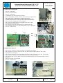
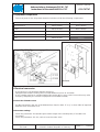
2.3 Anbau der Leiterplatte
–
Stecker 2 abziehen.
–
Deckel 1 abschrauben.
– Stecker 3 abziehen.
– Leiterplatte von den Rastnasen ziehen.
– Neue Leiterplatte 9 (9850 767015) auf Rastnasen aufstecken.
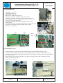
– Die auf der alten Leiterplatte 6 angeschlossenen
Leitungen der Stecker X23 bis X26 für die Magnetventile
einzeln abziehen und an die gleiche entsprechende Stelle
auf der neuen Leiterplatte 9 anschließen.
– Die im Bausatz befindliche Leitung 9870 767034 in den
Steuerkasten 8 einstecken.
– Das andere Ende der Leitung 9870 767034 wird in die
Steckverbindung X29 der Leiterplatte 9850 767015 gesteckt.
– Stecker 3 aufstecken.
2.4 Anbau des Sensors
– Den Sensor 5 mit den Senkschrauben am Oberteil befestigen.
– Die Leitung 11 zwischen dem Oberteil und dem Taster hindurchführen und in den
Kabelkanal 12 verlegen.
– Die Leitung durch die Tischplatte hindurchführen. Beim Verlegen unter der Tischplatte
ausreichenden Abstand zum Antriebsriemen des Oberteils halten!
– Die Leitung des Sensors wird in die Steckverbindung X30 der Leiterplatte 9850 767015
gesteckt.
– Deckel 1 wieder anschrauben.
– Stecker 2 aufstecken.
Anbauanleitung Umbausatz FSE Kl. 767
Instructions for the retrofit kit SSD cl. 767
Teile-Nr./ Part-No.:
0791 767707
Printed in Federal Republic of Germany
Ausgabe/Edition:
03.2006
Blatt: von
Sheet: 2 from 12
1
2
69(9850 767015)
ALT NEU
3
9
X30
X29
8
5
11
12

Teile-Nr./ Part-No.:
0791 767707
Printed in Federal Republic of Germany
Ausgabe/Edition:
03.2006
Blatt: von
Sheet: 3 from 12
Anbauanleitung Umbausatz FSE Kl. 767
Instructions for the retrofit kit SSD cl. 767

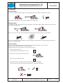
3. Einstellung der Fadenanzugsfeder
Für den einwandfreien Betrieb der FSE/SSD ist es w ichtig, dass die Federspannung der
Fadenanzugsfeder richtig eingestellt ist.
ACHTUNG!
Die Federkraft der Fadenanzugsfeder muss größer sein als die
Federkraft des FSE/SSD Sensors.
Einstellung der Fadenanzugsfeder (siehe Dürkopp Adler Serviceanleitung
der Kl. 767, Kapitel 9.2 Fadenanzugsfeder)
Anbauanleitung Umbausatz FSE Kl. 767
Instructions for the retrofit kit SSD cl. 767
Teile-Nr./ Part-No.:
0791 767707
Printed in Federal Republic of Germany
Ausgabe/Edition:
03.2006
Blatt: von
Sheet: 4 from 12

Teile-Nr./ Part-No.:
0791 767707
Printed in Federal Republic of Germany
Ausgabe/Edition:
03.2006
Blatt: von
Sheet: 5 from 12
4. Bedienung
4.1 Normaler Modus
Wird beim normalen Nähen ein Fehlstich erkannt, wird der Antrieb blockiert und die LED leuchtet auf.
Der Antrieb kann nur mit dem Touch-Key freigegeben werden.
4.2 Spuler-Modus
Um eine Spule aufzuspulen, wird in den Spuler-Modus gewechselt. Der Spuler-Modus wird
eingeschaltet, indem die FSE 5 Sekunden mit dem Touch-Key berührt wird.
Nach 5 Sekunden beginnt die LED zu blinken und zeigt s omit an, dass die Fadenüberwachung
ausgeschaltet ist.
Nun kann eine Spule aufgespult werden. Mit Betätigung des Fadenabschneiders wird die
Fadenüberwachung wieder eingeschaltet.
4.3 Service-Modus
Um mechanische Einstellungen an der Maschine vorzunehmen, kann der Service-Modus
eingeschaltet werden. Im Service-Modus ist die Fadenüberwachung ausgeschaltet.
Um in den Service-Modus zu gelangen sind folgende Schritte notwendig:
– Maschine ausschalten (länger als 2 Sekunden)
– FSE mit dem Touch-Key berühren und
– Maschine wieder einschalten
Die LED beginnt zu blinken und zeigt somit an, dass die Fadenüberwachung ausgeschaltet ist.
Der Service-Modus bleibt bis zum nächsten Ausschalten der Maschine aktiv. Die LED beginnt zu
blinken und zeigt somit an, dass die Fadenüberwachung ausgeschaltet ist.
Der Service-Modus bleibt bis zum nächsten Ausschalten der Maschine aktiv.
Anbauanleitung Umbausatz FSE Kl. 767
Instructions for the retrofit kit SSD cl. 767

Notizen:
Anbauanleitung Umbausatz FSE Kl. 767
Instructions for the retrofit kit SSD cl. 767
Teile-Nr./ Part-No.:
0791 767707
Printed in Federal Republic of Germany
Ausgabe/Edition:
03.2006
Blatt: von
Sheet: 6 from 12

Teile-Nr./ Part-No.:
0791 767707
Printed in Federal Republic of Germany
Ausgabe/Edition:
03.2006
Blatt: von
Sheet: 7 from 12
1. Equipment components
The set of parts for the skip stitch detection includes (SSD) the following components:
FSE 13-1 (0767 590264) FSE 13-2 (0767 590274)
Thread sensor 9815 740020 9815 740020
Cable 9870 767034 9870 767034
Key 0767 490383 0767 490383
Fillister head screws 0271 001655 0271 001655
PCB 9850 767015 existing
2. Electrical conversion
A conversion is only possible with the machines:
equipped with the Efka Sewing drive DC1600 DA82GA (since 01.01.1999).
If your sewing machine is equipped with older sewing drive, carry out the conversion only after
changing completely the electrical equipment (from 1988 to 1998)
2.1 Check the EPROM version
For the present kit is the use of the EPROM from Version 3312 “F” to “J” or from 3316 “A”required.
EPROM check Parameter 179
2.2 Parameter settings
Check the parameter 170 (Needle point at the height of the needle plate), if needed set it
accurately.
Check the parameter 171-2A, set it to have the value “034".
Anbauanleitung Umbausatz FSE Kl. 767
Instructions for the retrofit kit SSD cl. 767

2.3 Mounting the PCB
–
Unplug the connector 2.
–
Unscrew the cover 1.
– Unplug the connector 3.
– Remove the PCB 6 from the clips.
– Attach the new PCB 9 (9850 767015) to the clips.
– Unplug the cables of the plugs X23 to X26 one by one,
connected to PCB 6 and connect them to the PCB 9 to the
same and corresponding place.
– Plug the cable 9870 767034 provided with the kit to the
control box 8.
– The other end of the cable 9870 767034 has to be connected
to the plug connection X29 of the PCB 9850 767015.
– Plug in the connector 3.
2.4 Mounting the sensor
– Screw the sensor 5 onto the machine head using the provided fillister head screws.
– Lead the cable between the machine head and the key panel and lay it in the cable duct 12.
– Lead the cable 11 under the the table top. Make sure to leave enough room for the driving belt of
the machine head!
– Attach the plug (end of the cable 11) to the plug connection X30 of the PCB 9850 767015.
– Screw on the cover 1 again.
– Plug in the connector 2.
Anbauanleitung Umbausatz FSE Kl. 767
Instructions for the retrofit kit SSD cl. 767
Teile-Nr./ Part-No.:
0791 767707
Printed in Federal Republic of Germany
Ausgabe/Edition:
03.2006
Blatt: von
Sheet: 8 from 12
1
2
8
69(9850 767015)
ALT NEU
3
9
X30
X29
5
11
12

Teile-Nr./ Part-No.:
0791 767707
Printed in Federal Republic of Germany
Ausgabe/Edition:
03.2006
Blatt: von
Sheet: 9 from 12
Anbauanleitung Umbausatz FSE Kl. 767
Instructions for the retrofit kit SSD cl. 767

3. Setting the thread tension lift
In order to have a perfect operation of the FSE/SSD it is important to set correctly the spring
tension of the thread tension lift.
Attention!
The spring elasticity of the thread tension lift must be greater than
the spring elasticity of the FSE/SSD sensor.
Setting the thread tension lift (see Dürkopp Adler service instructions cl. 767,
chapter 9.2 Thread Tension Lift)
Anbauanleitung Umbausatz FSE Kl. 767
Instructions for the retrofit kit SSD cl. 767
Teile-Nr./ Part-No.:
0791 767707
Printed in Federal Republic of Germany
Ausgabe/Edition:
03.2006
Blatt: von
Sheet: 10 from 12

Teile-Nr./ Part-No.:
0791 767707
Printed in Federal Republic of Germany
Ausgabe/Edition:
03.2006
Blatt: von
Sheet: 11 from 12
4. Operating
4.1 Sewing Mode
In case of a skipped stitch during normal sewing, the motor stops and the LED shines.
The release of the motor c an be done by the touch-key only.
4.2 Bobbin Mode
For bobbin winding, the SSD has to be switched on into the bobbin mode. Hold the touch-key for
5 seconds onto the SSD.
After 5 seconds, the LED starts flashing indicating that the thread monitor is disabled.
Now you can start to wind a bobbin. By activating the foot pedal for thread trimming the thread
monitor is enabled again.
4.3 Service Mode
For mechanical adjustments, the SSD has to be switched into the service mode.
In this mode the thread monitor will be disabled.
Following steps are necessary to come into this mode.
– Switch off the machine
(it should be off for longer than 2 sec.)
– Hold the touch-key onto the SSD and
– Switch on the machine again
The LED flashes, indicating that the thread monitor is d isabled.
The machine stays in the service mode until it is switched off again.
Anbauanleitung Umbausatz FSE Kl. 767
Instructions for the retrofit kit SSD cl. 767

Notes:
Anbauanleitung Umbausatz FSE Kl. 767
Instructions for the retrofit kit SSD cl. 767
Teile-Nr./ Part-No.:
0791 767707
Printed in Federal Republic of Germany
Ausgabe/Edition:
03.2006
Blatt: von
Sheet: 12 from 12
-
 1
1
-
 2
2
-
 3
3
-
 4
4
-
 5
5
-
 6
6
-
 7
7
-
 8
8
-
 9
9
-
 10
10
-
 11
11
-
 12
12


in anderen Sprachen
- English: Duerkopp Adler 767 User manual
Verwandte Artikel
-
DURKOPP ADLER 767 Benutzerhandbuch
-
-
-
-
-
-
-
-
-