
2006/42/EC
NO
SAFETY
English
Photoelectric retro-reective sensor
Operating instructions
Safety notes
• Read the operating instructions before commissioning.
• Connection, mounting and setting may only be performed by trained
specialists.
• Not a safety component in accordance with the EU Machinery Directive.
• UL: Only for use in applications in accordance with NFPA 79. Adapters
listed by UL with connection cables are available. Enclosure type 1.
• When commissioning, protect the device from moisture and contamination.
• These operating instructions contain information required during the life
cycle of the sensor.
Correct use
The WL27-3 is an opto-electronic photoelectric retro-reective sensor
(referred to as “sensor” in the following) for the optical, non-contact detec-
tion of objects, animals and persons. A reector is required for this product
to function. If the product is used for any other purpose or modied in any
way, any warranty claim against SICK AG shall become void.
The WL27-3R /- 3S sensor is a class A product. In household environments,
devices of this kind can cause radio interference. The user should take
appropriate measures as required.
Commissioning
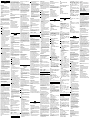
1 Adjust the distance between the sensor and the reector according to
the corresponding diagram (x = sensing range, y = operating reserve).
2 Mount the sensor and the reector using suitable mounting brackets
(see the SICK range of accessories). Align the sensor and reector with
each other.
Note the sensor's maximum permissible tightening torque of 1.3 Nm.
3 The sensors must be connected in a voltage-free state.
The information in the graphics [B] must be observed, depending on
the connection type:
– Male connector connection: pin assignment
– Cable (0.25 mm
2
): core color
Only apply voltage / switch on the power supply once all electrical
connections have been completed. The green LED indicator lights up
on the sensor.
Explanations of the connection graphic (graphic B):
Switching outputs Q and / Q (according to graphic B):
WL27-3P / -3F (PNP: load -> M)
WL27-3N / -3E (NPN: load -> L+)
WL27-3R / -3S (relay output)
Alarm / Health = alarm output (see Additional functions)
TE / Test = test input (see Additional functions)
Q: dark switching / light switching, object will not be detected,
relay active
4 Align the sensor with a suitable reector. Select the position so that the
red emitted light beam hits the center of the reector. The sensor must
have a clear view of the reector, with no object in the path of the beam
[see E]. You must ensure that the optical openings of the sensor and
reector are completely clear.
5 Sensor which it is not possible to set for the WL27-3xxxx0:
The sensor is adjusted and ready for operation.
After alignment is complete, move a non-transparent object into the
path of the beam. Refer to graphics C and G to check the function.
If the switching output fails to behave in accordance with graphic C,
check application conditions. See section Fault diagnosis.
Sensor with WL27-3xxxx1 potentiometer:
The sensitivity is adjusted with the potentiometer (type: 270°). Clock-
wise rotation: operating reserve increased; counterclockwise rotation:
operating reserve reduced. We recommend setting the potentiometer
to “Maximum”. A lower operating reserve may be necessary for
depolarizing surfaces again. The LED indicator does not light up again,
check the application conditions.
The sensor is adjusted and ready for operation. Refer to graphics C
and G to check the function. If the switching output fails to behave in
accordance with graphic C, check application conditions. See section
Fault diagnosis.
Additional functions
Alarm output: The sensor (WL27-3) features a pre-failure notication output
(“Alarm” or “Health” in connection diagram [B]), which issues a notication
if the sensor is only ready for operation to a limited extent. The LED indicator
ashes in this case.
Possible causes: Sensor or reector is contaminated, sensor is out of
alignment.
Alarm output:
in the good state: LOW (0), if excessively contaminated HIGH (1).
Health output:
in the good state: HIGH (1), if excessively contaminated or in the event of
cable interruption LOW (0).
Time types: WL27-3 F, -3E, -3R: t0 = no time delay, t1 = time delay, t2 = time
delay; for -3R: 0 = relay deactivated, 1 = relay active. Time stage selector
switch can be set on the device according to A.
Time stages: WL27-3F / -3E: < 0.5 s: 0.02 ... 0.5 s or
> 0.5 s: 0.5 ... 10 s can be set.
WL27-3R: 0.5 ... 10 s can be set
Test input: The sensors WL27-3F2631 / -3E2631 feature a test input
(“TI” or “Test” on the connection diagram [B]), which can be used to check
that the sensor is functioning correctly:
If female cable connectors with LED indicators are used, you must ensure
that the TI is assigned accordingly.
There must be no object between the sensor and reector; activate the test
input (see the connection diagram [B], TI at 0 V for PNP) (WL27-3F2631:
PNP: TI → M; WL27-3E2631: NPN: TI → L+).
The send LED is shut down or the detection of an object is simulated. Refer
to Graphics C and G to check the function. If the switching output fails to
behave in accordance with Graphic C, check application conditions. See
section Fault diagnosis.
Devices with special features
WL27-3P2430S01: sensing range max.: 0.1 … 4.3 m / PL80A, type of light:
red light, light beam diameter: approx. 90 mm at 4 m distance.
WL27-3R2631S02: timing element: can be set from 0.05 ... 1 sec.
WL27-3S3731S03: dark switching, no UL approval.
WL27-3F2631S04: PNP, response time: ≤ 200 µs, switching frequency:
2.500 Hz, timing element (on-delay): 30 ms or 70 ms can be set.
WL27-3V2430S05: with health output and Q / at pin 4.
WL27-3P2430S09: for extreme shock load.
WL27-302610S06: sensing range max.: 0.1 … 2.5 m / TR27 (reector
TR27: 1015387), type of light: infrared light, light beam diameter: approx.
250 mm at 2.5 m distance, supply voltage: 24 V DC … 120 V DC
2)
, power
consumption: ≤ 2.5 W, switching output: relay, switching current
(switching voltage): 200 mA (24 V DC…120 V DC), Enclosure rating IP65,
utilization category:
DC-21, in accordance with EN 60947-1.
WL27-302610P01: WL27-302610S06 is pre-mounted on mounting
brackets.
WL27-3F2431S27: PNP, response time: ≤ 200 µs, switching frequency:
2.500 Hz, timing element (on-delay): 30 ms or 70 ms can be set, through
holes with metal sleeves.
WL27-302630S12: sensing range max.: 0.1 … 1.7 m / PL30A, type of
light: red light, light beam diameter: approx. 10 mm at 400 mm distance,
dark switching light switching
2 1 t = 1
1 2 t = 2
supply voltage: 10 V DC ... 30 V DC, power consumption: ≤ 45 mA switching
current (switching voltage): 100 mA (20 V AC), 100 mA (30 V DC), output:
semiconductor relay, galvanically isolated, response time: ≤ 3 ms, switching
frequency: 200 Hz.
WL27-3P2460S14: sensing range max.: 0.1 … 3 m / PL80A, type of light:
red light, PinPoint LED light beam diameter: approx. 30 mm at 3 m distance,
response time: ≤ 2.5 ms, switching frequency: 200 Hz.
Fault diagnosis
Table I indicates which measures are to be taken if the sensor stops working.
Disassembly and disposal
The sensor must be disposed of according to the applicable country-specic
regulations. Eorts should be made during the disposal process to recycle
the constituent materials (particularly precious metals).
Maintenance
SICK sensors are maintenance-free.
We recommend doing the following regularly:
– Clean the external lens surfaces
– Check the screw connections and plug-in connections
No modications may be made to devices.
Subject to change without notice. Specied product properties and
technical data are not written guarantees.
Anzeige-LED / Fehlerbild /
LED indicator / fault pattern
Ursache /
Cause
Maßnahme /
Measures
grüne LED leuchtet nicht /
green LED does not light up
keine Spannung oder Spannung unterhalb der
Grenzwerte /
No voltage or voltage below the limit values
Spannungsversorgung prüfen, den gesamten
elektrischen Anschluss prüfen (Leitungen und
Steckerverbindungen) /
Check the power supply, check all electrical
connections (cables and plug connections)
grüne LED leuchtet nicht /
green LED does not light up
Spannungsunterbrechungen /
Voltage interruptions
Sicherstellen einer stabilen Spannungsversorgung
ohne Unterbrechungen /
Ensure there is a stable power supply without
interruptions
grüne LED leuchtet nicht /
green LED does not light up
Sensor ist defekt /
Sensor is faulty
Wenn Spannungsversorgung in Ordnung ist, dann
Sensor austauschen /
If the power supply is OK, replace the sensor
grüne LED leuchtet, kein Ausgangssignal bei
Objektdetektion /
green LED lights up, no output signal when object
is detected
Testeingang (TE) ist nicht korrekt angeschlossen /
Test input (TI) is not connected properly
Siehe Hinweis für Anschluss des TE /
See the note on connecting the TI
gelbe LED blinkt, wenn Alarm / Health vorhanden, dann
entsprechendes Ausgangssignal beachten /
Yellow LED flashes; if Alarm / Health is present then take
note of the corresponding output signal
Sensor ist noch betriebsbereit, aber die Betriebsbe–
dingungen sind nicht optimal / zusätzlich bei
Health-Ausgang: Spannungsversorgung ist unterbrochen /
Sensor is still ready for operation, but the operating
conditions are not ideal / additionally with health output:
power supply interrupted
Betriebsbedingungen prüfen: Lichtstrahl (Lichtfleck)
vollständig auf den Reflektor ausrichten / Reinigung
der optischen Flächen(Sensor und Reflektor) / Emp-
findlichkeit (Potentiometer) neu einstellen / falls
Potentiometer auf max. Schaltabstand eingestellt:
Abstand zwischen Sensor und Reflektor verringern
sowie Reflektortyp mit Grafik H überprüfen / Reflektor
eignet sich nicht für gewählte Applikation (wir empfeh-
len, ausschließlich SICK-Reflektoren zu verwenden) /
Schaltabstand überprüfen und ggf. anpassen, siehe
Grafik H. / Abstand zwischen Sensor und Reflektor ist
zu groß / bei Health-Ausgang: Spannungsversorgung
prüfen, den gesamten elektrischen Anschluss prüfen
(Leitungen und Steckverbindungen) /
Check the operating conditions: Fully align the beam
of light (light spot) with the reflector. / Clean the
optical surfaces (sensor and reflector). / Readjust the
sensitivity (potentiometer) / If the potentiometer is
set to the max. sensing range: Reduce the distance
between the sensor and the reflector, and check the
reflector type against graphic H. / Reflector is not sui-
table for the application in question (we recommend
only using SICK reflectors) / Check sensing range and
adjust if necessary; see graphic H. / Distance between
the sensor and the reflector is too long / With health
output: Check the power supply, check all electrical
connections (cables and plug connections).
Signalunterbrechungen bei Objektdetektion /
Signal interruptions when object is detected
Depolarisierende Eigenschaft der Objektoberfläche
(z. B. Folie), Umspiegelung
Depolarizing property of the object surface
(e. g., tape), reflection
Empfindlichkeit reduzieren oder Sensorposition
verändern /
Reduce sensitivity or change the position of the sensor
WL27-3xxx3x -3x263x WL27-3xxx6x WL27-3Sxx3x WL27-3R263x
1)
Distanza di commutazione
(con riflettore PL80A)
Distancia de conmutación
(con reflector PL80A)
开关距离
(带反射器 PL80A)
最大検出範囲
(リフレクタを用いた場合PL80A)
Расстояние срабатывания
(с отражателем PL80A)
0.1 ...11 m 0.1 ...11 m 0.1 ...14 m 0.1 ...11 m 0.1 ...11 m
Distanza max. di commutazione
(con riflettore PL80A)
Distancia de conmutación max.
(con reflector PL80A)
最大开关距离
(带反射器 PL80A)
最大検出範囲
(リフレクタを用いた場合PL80A)
Расстояние срабатывания, макс.
(с отражателем PL80A)
0.1 ...15 m 0.1 ...15 m 0.1 ...19 m 0.1 ...15 m 0.1 ...15 m
Diametro punto luminoso / distanza Diámetro del punto luminoso / distancia
光斑直径 / 距离 光点のスポット径 / 距離 Диаметр светового пятна / расстояние
Tensione di alimentazione U
B
Tensión de alimentación U
B
供电电压 U
B
供給電圧 U
B
Напряжение питания U
B
0 ... 30 V DC
2)
0 ... 30 V DC
2)
0 ... 30 V DC
2)
20 ... 250 V AC / DC
3)
20 ... 250 V AC / DC
3)
Corrente di uscita I
max
Intensidad de salida I
max
输出电流 I
max
出力電流 I
max
Выходной ток I
max
100 mA 100 mA 100 mA 4 A @ 250 V AC, 4 A @24 V DC,
0.125 A @ 250 V DC
4)
10)
4 A @ 250 V AC, 4 A @24 V DC,
0.125 A @ 250 V DC
4)
10)
Frequenza di commutazione Frecuencia de conmutación
开关频率 スイッチング周波数
Частота переключения 1,000 Hz
5)
1,000 Hz
5)
1,000 Hz
5)
10 Hz
5)
10 Hz
5)
Tempo di reazione Tiempo de respuesta
响应时间 応答時間
Время отклика ≤ 0.5 ms
6)
≤ 0.5 ms
6)
≤ 0.5 ms
6)
≤ 10 ms
6)
≤ 10 ms
6)
Tipo di protezione Tipo de protección
防护类型 保護等級
Класс защиты IP 67, IP 69 IP 65 IP 67, IP 69 IP 66, IP 67 IP 65
Classe di protezione Clase de protección
防护等级 保護クラス
Класс защиты
7)
7)
8)
8)
8)
Commutazioni di protezione Circuitos de protección 保护电路 回路保護 Схемы защиты A, B, C
9)
A, B, C
9)
A, B, C
9)
A, C
9)
A,C
9)
Temperatura ambientale di funzionamento Temperatura ambiente de servicio
工作环境温度
周辺温度
(作動中) Диапазон рабочих температур -40 °C ... +60 °C -40 °C ... +60 °C -40 °C ... +60 °C -40 °C ... +60°C
10)
-40 °C ... +60 °C
10)
1)
I contatti di uscita relè sono separati dalla tensione di alimentazione da un
isolamento base di 3 mm.
2)
Valori limite; ondulazione residua max. 5 V
SS
,
corrente nominale connettore maschio: I
N
= 4A
3)
Valori limite; corrente nominale connettore maschio: I
N
= 4A
4)
Categoria d‘uso: AC-15. DC-13 (EN 60947-1)
5)
Con rapporto chiaro / scuro 1:1
6)
Durata segnale con carico ohmico
7)
Tensione nominale di isolamento U
i
= CC 50 V, categoria di sovratensione II
8)
Tensione nominale di isolamento U
i
= CA 250 V, categoria di sovratensione II
9)
A = U
B
-Allacciamenti protetti dall‘inversione di polarità
B = entrate e uscite protette da polarità inversa
C = Soppressione impulsi di disturbo
1)
Los contactos de salida de relé se encuentran aislados de la tensión de
alimentación por medio de un aislamiento básico de 3 mm.
2)
Valores límite;
ondulación residual max. 5 V
SS
,
corriente nominal del conector macho: I
N
= 4A
3)
Valores límite; corriente nominal del conector macho: I
N
= 4A
4)
Categoría de uso AC-15. DC-13 (EN 60947-1)
5)
Con una relación claro / oscuro de 1:1
6)
Duración de la señal con carga óhmica
7)
Tensión nominal de aislamiento U
i
= CC 50 V, categoría de sobretensión II
8)
Tensión nominal de aislamiento U
i
= CA 250 V, categoría de sobretensión II
9)
A = U
B
protegidas contra polarización inversa
B = Entradas y salidas protegidas contra polarización incorrecta
C = Supresión de impulsos parásitos
1)
利用 3 mm 的基本绝缘装置隔离继电 器输出触点和供电电压。
2)
极限值;最大余波 5 V
SS
,
额定电流插头:I
N
=4A
3)
极限值; 额定电流插头:I
N
=4A
4)
工作等级: AC-15. DC-13 (EN 60947-1)
5)
明暗比为 1:1
6)
信号传输时间(电阻负载时)
7)
額定絕緣電壓 U
i
= DC 50 V, 过电压类别 II
8)
額定絕緣電壓 U
i
= AC 250 V, 过电压类别 II
9)
A = U
B
接口(已采取反极性保护措施)
B = 具有反极性保护的输入端和输出端
C = 抑制干扰脉冲
1)
リレー出力接点は供給電圧から 3 mm の基本絶縁材で分離され
ています。
2)
限界値;残留リップルは最大 5 V
SS
、
オスコネクタ定格電流: I
N
= 4A
3)
限界値; オスコネクタ定格電流: I
N
= 4A
4)
使用カテゴリ: AC-15. DC-13 (EN 60947-1)
5)
ライト / ダークの比率 1:1
6)
負荷のある信号経過時間
7)
定格絶縁電圧 U
i
= DC 50 V, 過電圧カテゴリー II
8)
定格絶縁電圧 U
i
= AC 250 V, 過電圧カテゴリー II
9)
A = U
B
接続は逆接保護
B = 入力および出力は逆接保護
C = 干渉抑制
1)
Выходные релейные контакты отделены от напряжения питания базисной
изоляцией толщиной 3 мм.
2)
Предельные значения; остаточная волнистость макс. 5 B
SS
,
номинальный ток штекер: вход = 4A
3)
Предельные показатели; номинальный ток штекер: вход = 4A
4)
категория применения: AC-15. DC-13 (EN 60947-1)
5)
Соотношение светлых и темных участков изображения 1:1
6)
Продолжительность сигнала при омической нагрузке
7)
Номинальное напряжение изоляции U
i
= DC 50 V, категория перенапряжения II
8)
Номинальное напряжение изоляции U
i
= AC 250 V,
категория перенапряжения II
9)
A = U
B
-подключения с защитой от перепутывания полюсов
B = входы и выходы с защитой от перепутывания полюсов
C = подавление импульсных помех
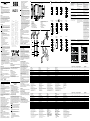
WL27-3
24.6
(0.97)
54 (2.13)
40 (1.57)
50 (1.97)
5.2
(0.20)
45 (1.77)
10
(0.39)
8.4
(0.33)
12.2
(0.48)
80.6 (3.17)
70 (2.76)
49.4 (1.94)
46.2 (1.82)
23
(0.91)
1
2
3
8
7
6
45 45
Q (PNP)
L
1
0
1
0
L
D
D
t0 t1 t0 t2
Q (NPN)
(PNP)
(NPN)
Deutsch
Reexions-Lichtschranke
Betriebsanleitung
Sicherheitshinweise
• Vor der Inbetriebnahme die Betriebsanleitung lesen.
• Anschluss, Montage und Einstellung nur durch Fachpersonal.
• Kein Sicherheitsbauteil gemäß EU-Maschinenrichtlinie.
• UL: Nur zur Verwendung in Anwendungen gemäß NFPA 79. Von UL
gelistete Adapter mit Anschlusskabeln sind verfügbar.
Enclosure type 1.
• Gerät bei Inbetriebnahme vor Feuchte und Verunreinigung schützen.
• Diese Betriebsanleitung enthält Informationen, die während des
Lebenszyklus des Sensors notwendig sind.
Bestimmungsgemäße Verwendung
Die WL27-3 ist eine optoelektronische Reexions-Lichtschranke (im Folgen-
den Sensor genannt) und wird zum optischen, berührungslosen Erfassen
von Objekten, Tieren und Personen eingesetzt. Zur Funktion wird ein Re-
ektor benötigt. Bei jeder anderen Verwendung und bei Veränderungen am
Produkt verfällt jeglicher Gewährleistungsanspruch gegenüber der SICK AG.
Die WL27-3R und WL27-3S sind Produkte der Klasse A. In Haushaltsumge-
bungen können diese Geräte Rundfunktstörungen verursachen, weshalb der
Anwender gegebenenfalls geeignete Maßnahmen ergreifen muss.
Inbetriebnahme
1 Distanz zwischen Sensor und Reektor mit dem zugehörigen Diagramm
[vgl. H] abgleichen (x = Schaltabstand, y = Funktionsreserve).
2 Sensor und Reektor an geeignete Befestigungswinkel montieren
(siehe SICK-Zubehör-Programm). Sensor und Reektor zueinander
ausrichten.
Maximal zulässiges Anzugsdrehmoment des Sensors von 1,3 Nm
beachten.
3 Anschluss der Sensoren muss spannungsfrei erfolgen.
Je nach Anschlussart sind die Informationen in den Graken [vgl. B]
zu beachten:
– Steckeranschluss: Pinbelegung
– Leitung (0,25 mm
2
): Adernfarbe
Erst nach Anschluss aller elektrischen Verbindungen die Span-
nungsversorgung anlegen bzw. einschalten. Am Sensor leuchtet die
grüne Anzeige-LED.
Erläuterungen zum Anschlussschema (gemäß Grak B):
Schaltausgänge Q bzw. / Q (gemäß Grak B):
WL27-3P / -3F (PNP: Last -> M)
WL27-3N / -3E (NPN: Last -> L+)
WL27-3R / -3S (Ausgang Relais)
Alarm / Health = Alarmausgang (siehe Zusatzfunktionen)
TE / Test = Testeingang (siehe Zusatzfunktionen)
Q: dunkelschaltend / hellschaltend, Objekt wird nicht erkannt,
Relais aktiv
4 Sensor auf geeigneten Reektor ausrichten. Positionierung so wählen,
dass der rote Sendelichtstrahl in der Mitte des Reektors auftrit.
Der Sensor muss freie Sicht auf den Reektor haben, es darf sich kein
Objekt im Strahlengang benden [vgl. E]. Es ist darauf zu achten, dass
die optischen Önungen von Sensor und Reektor vollständig frei sind.
5 Sensor ohne Einstellmöglichkeit WL27-3xxxx0: Sensor ist eingestellt
und betriebsbereit.
Nach durchgeführter Ausrichtung ein nicht-transparentes Objekt in
den Strahlengang führen. Zur Überprüfung der Funktion Grak C und
G heranziehen. Verhält sich der Schaltausgang nicht gemäß Grak C,
Einsatzbedingungen prüfen. Siehe Abschnitt Fehlerdiagnose.
Sensor mit Potentiometer WL27-3xxxx1:
Mit dem Potentiometer (Art: 270°) wird die Empndlichkeit eingestellt.
Drehung nach rechts: Erhöhung der Funktionsreserve, Drehung nach
links: Verringerung der Funktionsreserve. Wir empfehlen, das Potentio–
meter auf „Maximal“ zu stellen. Bei depolarisierenden Oberächen
kann eine geringere Funktionsreserve empfehlenswert sein. Leuchtet
die Anzeige-LED nicht wieder, Einsatzbedingungen prüfen.
Sensor ist eingestellt und betriebsbereit. Zur Überprüfung der Funktion
Grak C und G heranziehen. Verhält sich der Schaltausgang nicht
gemäß Grak C, Einsatzbedingungen prüfen.
Siehe Abschnitt Fehlerdiagnose.
Zusatzfunktionen
Alarmausgang: Der Sensor (WL27-3) verfügt über einen Vorausfall-
meldeausgang („Alarm“ oder „Health“ im Anschlussschema [B]), der
meldet, wenn der Sensor nur noch eingeschränkt betriebsbereit ist.
Dabei blinkt die Anzeige-LED.
Mögliche Ursachen: Verschmutzung von Sensor oder Reektor, Sensor
ist dejustiert.
Alarm-Ausgang:
Im Gutzustand: LOW (0), bei zu starker Verschmutzung HIGH (1).
Health-Ausgang:
Im Gutzustand: HIGH (1), bei zu starker Verschmutzung oder Leitungsunter-
brechung LOW (0).
Zeitarten: WL27-3F, -3E, -3R: t0 = keine Zeitverzögerung, t1 = Zeitver-
zögerung, t2 = Zeitverzögerung; für -3R gilt: 0 = Relais inaktiv, 1 = Relais
aktiv. Zeitstufen-Wahlschalter, einstellbar am Gerät gemäß A.
Zeitstufen: WL27-3F / -3E: < 0,5 s: 0,02 ... 0,5 s oder
> 0,5 s: 0,5 ... 10 s einstellbar.
WL27-3R: 0,5 ... 10 s einstellbar
Testeingang: Die Sensoren WL27-3F2631 / -3E2631 verfügen über
einen Testeingang („TE“ oder „Test“ im Anschlussschema [B]), mit dem
die ordnungsgemäße Funktion des Sensors überprüft werden kann:
Bei Verwendung von Leitungsdosen mit LED-Anzeigen ist darauf zu achten,
dass der TE entsprechend belegt ist.
Es darf sich kein Objekt zwischen Sensor und Reektor benden,
Testeingang aktivieren (siehe Anschlussschema [B], TE nach 0 V bei PNP)
(WL27-3F2631: PNP: TE → M; WL27-3E2631: NPN: TE → L+). Sende-LED
wird abgeschaltet, bzw. es wird simuliert, dass ein Objekt erkannt wird.
Zur Überprüfung der Funktion Grak C und G heranziehen. Verhält sich der
Schaltausgang nicht gemäß Grak C, Einsatzbedingungen prüfen. Siehe
Abschnitt Fehlerdiagnose.
Geräte mit besonderen Merkmalen
WL27-3P2430S01: Schaltabstand max.: 0,1 … 4,3 m / PL80A,
Lichtart: Rotlicht, Lichteckdurchmesser: ca. 90 mm in 4 m Entfernung.
WL27-3R2631S02: Zeitglied: Einstellbar 0,05 ... 1 sec.
WL27-3S3731S03: Dunkelschaltend, keine UL-Zulassung.
WL27-3F2631S04: PNP, Ansprechzeit: ≤ 200 µs, Schaltfrequenz: 2.500 Hz,
Zeitglied (Anzugsverzögerung): 30 ms oder 70 ms einstellbar.
WL27-3V2430S05: Mit Health-Ausgang und Q / auf Pin 4.
WL27-3P2430S09: für Extremschockbelastung.
WL27-302610S06: Schaltabstand max.: 0,1 … 2,5 m / TR27 (Reektor
TR27: 1015387), Lichtart: Infrarotlicht, Lichteckdurchmesser: ca. 250 mm
in 2,5 m Entfernung, Versorgungsspannung: 24 V DC … 120 V DC
2)
,
Leistungsaufnahme: ≤ 2,5 W, Schaltausgang: Relais, Schaltstrom
(Schaltspannung): 200 mA (24 V DC … 120 V DC), Schutzart IP65,
Gebrauchskategorie: DC-21, nach EN 60947-1.
WL27-302610P01: WL27-302610S06 ist auf Befestigungswinkel
vormontiert.
WL27-3F2431S27: PNP, Ansprechzeit: ≤ 200 µs, Schaltfrequenz: 2.500 Hz,
Zeitglied (Anzugsverzögerung): 30 ms oder 70 ms einstellbar, Durchgangs-
bohrung mit Metallhülsen.
WL27-302630S12: Schaltabstand max.: 0,1 … 1,7 m / PL30A, Lichtart:
Rotlicht, Lichteckdurchmesser: ca. 10 mm in 400 mm Entfernung, Ver-
sorgungsspannung: 10 V DC ... 30 V DC, Leistungsaufnahme: ≤ 45 mA
Schaltstrom (Schaltspannung): 100 mA (20 V AC), 100 mA (30 V DC),
Ausgang: Halbleiter-Relais, galvanisch getrennt, Ansprechzeit:
≤ 3 ms, Schaltfrequenz: 200 Hz.
WL27-3P2460S14: Schaltabstand max.: 0,1 … 3 m / PL80A, Lichtart:
Rotlicht, PinPoint-LED Lichteckdurchmesser: ca. 30 mm in 3 m Entfernung,
Ansprechzeit: ≤ 2,5 ms, Schaltfrequenz: 200 Hz
Fehlerdiagnose
Tabelle I zeigt, welche Maßnahmen durchzuführen sind, wenn die Funktion
des Sensors nicht mehr gegeben ist.
Demontage und Entsorgung
Die Entsorgung des Sensors hat gemäß den länderspezisch anwendbaren
Vorschriften zu erfolgen. Für die enthaltenen Wertstoe (insbesondere
Edelmetalle) ist im Rahmen der Entsorgung eine Verwertung anzustreben.
Wartung
SICK-Sensoren sind wartungsfrei.
Wir empfehlen, in regelmäßigen Abständen
– die optischen Grenzächen zu reinigen
– Verschraubungen und Steckverbindungen zu überprüfen
Veränderungen an Geräten dürfen nicht vorgenommen werden.
Irrtümer und Änderungen vorbehalten. Angegebene Produkteigenschaften
und technische Daten stellen keine Garantieerklärung dar.
dunkelschaltend hellschaltend
2 1 t = 1
1 2 t = 2
+ (L+)
Q
- (M)
brn
wht
blu
Q
blk
+ (L+)
Q
- (M)
brn
wht
blu
blk
1
2
3
Q
4
+ (L+)
Q
- (M)
brn
wht
blu
1
2
3
blk
4
+ (L+)
- (M)
not connecte
d
1
2
3
Q
4
Q
5
Test
6
brn
blu
blk
wht
gra
10
0
10
1
y
Diamond
Grade
PL20
PL40 A
PL80 A
2
(0.79)
4
(1.57)
6
(2.36)
8
(3.15)
10
(3.94)
12
(4.72)
14
(5.51)
16
(6.30)
x
Distance in m (inch)
WL27-3xxx3x -3x263x WL27-3xxx6x WL27-3Sxx3x WL27-3R263x
1)
Sensing range
(with reflector PL80A)
Schaltabstand
(mit Reflektor PL80A)
Portée
(avec réflecteur PL80A)
Distância de comutação
(com refletor PL80A)
0.1 ...11 m 0.1 ...11 m 0.1 ...14 m 0.1 ...11 m 0.1 ...11 m
Sensing range max.
(with reflector PL80A)
Schaltabstand max.
(mit Reflektor PL80A)
Portée max.
(avec réflecteur PL80A)
Distância de comutação max.
(com refletor PL80A)
0.1 ...15 m 0.1 ...15 m 0.1 ...19 m 0.1 ...15 m 0.1 ...15 m
Light spot diameter / distance Lichtfleckdurchmesser / Entfernung Diamètre spot / distance Diâmetro do ponto de luz / distância
Supply voltage U
B
Versorgungsspannung U
B
Tension d'alimentation U
B
Tensão de alimentação U
B
0 ... 30 V DC
2)
0 ... 30 V DC
2)
0 ... 30 V DC
2)
20 ... 250 V AC / DC
3)
20 ... 250 V AC / DC
3)
Output current I
max
Ausgangsstrom I
max
Courant de sortie I
max
Corrente de saída I
max
100 mA 100 mA 100 mA 4 A @ 250 V AC, 4 A @24 V DC,
0.125 A @ 250 V DC
4)
10)
4 A @ 250 V AC, 4 A @24 V DC,
0.125 A @ 250 V DC
4)
10)
Switching frequency Schaltfrequenz Fréquence de commutation Frequência de comutação 1,000 Hz
5)
1,000 Hz
5)
1,000 Hz
5)
10 Hz
5)
10 Hz
5)
Max. response time Ansprechzeit max. Temps de réponse max. Tempo de resposta ≤ 0.5 ms
6)
≤ 0.5 ms
6)
≤ 0.5 ms
6)
≤ 10 ms
6)
≤ 10 ms
6)
Enclosure rating Schutzart Indice de protection Tipo de proteção IP 67, IP 69 IP 65 IP 67, IP 69 IP 66, IP 67 IP 65
Protection class Schutzklasse Classe de protection Classe de proteção
7)
7)
8)
8)
8)
Circuit protection Schutzschaltungen Protections électriques Circuitos de proteção A, B, C
9)
A, B, C
9)
A, B, C
9)
A, C
9)
A,C
9)
Ambient operating temperature Betriebsumgebungstemperatur Température de service Temperatura ambiente de funcionamento -40 °C ... +60 °C -40 °C ... +60 °C -40 °C ... +60 °C -40 °C ... +60°C
10)
-40 °C ... +60 °C
10)
1)
Relay contacts are separated from the supply voltage by a basic isolation
of 3 mm.
2)
Limit value; residual ripple max. 5 V
SS
,
male connector rated current: I
N
= 4A
3)
Limit values; male connector rated current: I
N
=4A
4)
Utilization category: AC-15. DC-13 (EN 60947-1)
5)
With light / dark ratio 1:1
6)
Signal transit time with resistive load
7)
Rated insulation voltage U
i
= DC 50 V, overvoltage category II
8)
Rated insulation voltage U
i
= AC 250 V, overvoltage category II
9)
A = U
B
-connections reverse polarity protected
B = inputs and output reverse-polarity protected
C = Interference suppression
1)
Relaisausgangskontakte sind von der Versorgungsspannung durch eine
Basisisolation von 3 mm getrennt.
2)
Grenzwerte; Restwelligkeit max. 5 V
SS
,
Nennstrom Stecker: I
N
=4 A.
3)
Grenzwerte; Nennstrom Stecker: I
N
=4 A
4)
Gebrauchskategorie: AC-15. DC-13 (EN 60947-1)
5)
Mit Hell- / Dunkelverhältnis 1:1
6)
Signallaufzeit bei ohmscher Last
7)
Bemessungsisolationsspannung U
i
= DC 50 V, Überspannungsschutz II
8)
Bemessungsisolationsspannung U
i
= AC 250 V, Überspannungsschutz II
9)
A = U
B
-Anschlüsse verpolsicher
B = Ein- und Ausgänge verpolsicher
C = Störimpulsunterdrückung
1)
Les contacts de sortie de relais sont isolés de la tension d‘alimentation par
une isolation de base de 3 mm.
2)
Valeurs limites;
ondulation résiduelle max. 5 V
CC
,
courant nominal du connecteur : I
N
= 4 A
3)
Valeurs limites; courant nominal du connecteur : I
N
= 4 A
4)
Catégorie d’utilisation : AC-15. DC-13 (EN 60947-1)
5)
Pour un rapport clair / sombre de 1:1
6)
Temps de propagation du signal sur charge ohmique
7)
Tension d‘isolation U
i
= 50 V CC, catégorie de surtension II
8)
Tension d‘isolation U
i
= 250 V CA, catégorie de surtension II
9)
A = raccordements U
B
protégés contre les inversions de polarité
B = entrées et sorties protégées contre les inversions de polarité
C = Suppression des impulsions parasites
1)
Os contatos de saída de relé estão separados da tensão de alimentação
por uma isolação de base de 3 mm.
2)
Valores limite; ondulação residual max. 5 V
SS
,
corrente nominal conector macho: I
N
=4A
3)
Valores-limite; corrente nominal conector macho: I
N
=4A
4)
Categoria de uso: AC-15. DC-13 (EN 60947-1)
5)
Com proporção sombra / luz 1:1
6)
Tempo de funcionamento do sinal com carga ôhmica
7)
Tensão nominal de isolamento U
i
= CC 50 V, categoria de sobretensão II
8)
Tensão nominal de isolamento U
i
= CA 250 V, categoria de sobretensão II
9)
A = conexões protegidas contra inversão de pólos U
B
B = Entradas e saídas protegidas contra polaridade inversa
C = Supressão de impulsos parasitas
10)
UL:
4A @ 250V AC, general use
4A @ 250V AC, resistive (NO)
3A @ 250V AC, resistive (NC)
4A @ 24V DC, NO, general use
3A @ 24V DC, NC, general use
R300
B300 (NO contacts only)
0 °C ... +60 °C
-3x24xx
-3x34xx
-3x11xx
-3x12xx
-3x17xx
-3x18xx
-3K24xx -3x26xx DC
WL27-3xxx3x WL27-3xxx6x
+ (L+)
Health
- (M)
brn
wht
blu
1
2
3
Q
blk
4
+ (L+)
Health
- (M)
brn
wht
blu
1
2
3
Q
blk
4
+ (L+)
- (M)
brn
blu
gra
blk
wht
1
2
not connected
6
3
4
5
+ (L+)
+ (L+)
Q
4
1
3
- (M)
2
- (M)
5
not connected
6
Diamond
Grade
PL20
PL40 A
PL80 A
1
10
100
Y
x2
(0.79)
6
(2.36)
10
(3.94)
14
(5.51)
18
(7.09)
Distance in m (inch)
-3x15xx AC / DC
-3x16xx AC / DC
-3x26xx AC / DC -3x37xx AC / DC
L1
N
brn
blu
gra
blk
wht
L1
N
1
2
not connected
6
not connected
7
3
4
5
L1
N
brn
blu
gra
blk
wht
1
2
not connected
6
3
4
5
-3x37xx DC
WL27-302610S12,
1045988
WL27-302610S06,
2035146
WL27-3V2430S05,
1028074
WL27-3V2430,
1028063
+ (L+)
- (M)
not connected
1
2
3
Q
4
Q
5
not connected
6
not connected
7
-------------------------------------------------------- 8010964.13VN 0519 COMAT ------------------------------------------------------
1 Optical axis sender /
Optikachse Sender
2 Optical axis receiver /
Optikachse Empfänger
3 Mounting hole Ø 5.2 mm (0.20) /
Befestigungsbohrung Ø 5.2 mm (0.20)
4 Status indicator LED green: power on /
Anzeige-LED grün: Spannungsversorgung an
5 Status indicator LED, yellow: Status of received light beam /
Anzeige-LED gelb: Status Lichtempfang
6 Time control /
Zeitsteuerung
7 Time delay selector switch /
Schalter zur Wahl der Zeitverzögerung
8 Sensitivity control /
Empndlichkeitssteuerung
A B
C E
G
H
I
BZ int49
Detailed addresses and further locations at www.sick.com
Australia
Phone +61 (3) 9457 0600
1800 33 48 02 –
tollfree
Austria
Phone +43 (0) 2236 62288-0
Belgium/Luxembourg
Phone +32 (0) 2 466 55 66
Brazil
Phone +55 11 3215-4900
Canada
Phone +1 905.771.1444
Czech Republic
Phone +420 234 719 500
Chile
Phone +56 (2) 2274 7430
China
Phone +86 20 2882 3600
Denmark
Phone +45 45 82 64 00
Finland
Phone +358-9-25 15 800
France
Phone +33 1 64 62 35 00
Germany
Phone +49 (0) 2 11 53 010
Greece
Phone +30 210 6825100
Hong Kong
Phone +852 2153 6300
Hungary
Phone +36 1 371 2680
India
Phone +91-22-6119 8900
Israel
Phone +972 97110 11
Italy
Phone +39 02 27 43 41
Japan
Phone +81 3 5309 2112
Malaysia
Phone +603-8080 7425
Mexico
Phone +52 (472) 748 9451
Netherlands
Phone +31 (0) 30 229 25 44
New Zealand
Phone +64 9 415 0459
0800 222 278 – tollfree
Norway
Phone +47 67 81 50 00
Poland
Phone +48 22 539 41 00
Romania
Phone +40 356-17 11 20
Russia
Phone +7 495 283 09 90
Singapore
Phone +65 6744 3732
Slovakia
Phone +421 482 901 201
Slovenia
Phone +386 591 78849
South Africa
Phone +27 10 060 0550
South Korea
Phone +82 2 786 6321/4
Spain
Phone +34 93 480 31 00
Sweden
Phone +46 10 110 10 00
Switzerland
Phone +41 41 619 29 39
Taiwan
Phone +886-2-2375-6288
Thailand
Phone +66 2 645 0009
Turkey
Phone +90 (216) 528 50 00
United Arab Emirates
Phone +971 (0) 4 88 65 878
United Kingdom
Phone +44 (0)17278 31121
USA
Phone +1 800.325.7425
Vietnam
Phone +65 6744 3732
SICK AG, Erwin-Sick-Strasse 1, D-79183 Waldkirch
Seite wird geladen ...
-
 1
1
-
 2
2


in anderen Sprachen
- English: SICK SENSICK WL27-3 Operating instructions
- français: SICK SENSICK WL27-3 Mode d'emploi
- español: SICK SENSICK WL27-3 Instrucciones de operación
- italiano: SICK SENSICK WL27-3 Istruzioni per l'uso
- русский: SICK SENSICK WL27-3 Инструкция по эксплуатации
- português: SICK SENSICK WL27-3 Instruções de operação
- 日本語: SICK SENSICK WL27-3 取扱説明書
Verwandte Artikel
-
SICK WL23-2 Compact photoelectric sensor Bedienungsanleitung
-
-
-
-
-
-
-
-
-