Audi 8J0 051 434 Installation Instructions Manual
- Typ
- Installation Instructions Manual

Original Zubehör
Audi
Abbildung Illustration
Änderungen vorbehalten. Subject to change without prior notice. Stand: 06/2010 © 2010 AUDI AG, Ingolstadt
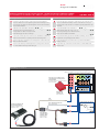
Montageschritte Installing the wiring harness
1
Lösen Sie am Radio/Navigationssystem die Leitung D15 (+12V) aus. Verrasten
Sie die Leitung in das 2-pol. Zusatzgehäuse des Leitungssatzes so, dass sie mit
der roten Leitung am 2-pol. Gegengehäuse des Leitungssatzes verbunden wird.
1
Release pin D15 (+12V) from the Quadlok connector of the radio/navigation
system and connect it to the black wire of the 2-way cage of the harness.
2
Lösen Sie am Radio/Navigationssystem die Leitung D12 (Masse) aus. Verrasten
Sie die Leitung in das 2-pol. Zusatzgehäuse des Leitungssatzes so, dass sie mit
der schwarzen Leitung am 2-pol. Gegengehäuse des Leitungssatzes verbunden
wird.
2
Release pin D12 (GND) from the Quadlok connector of the radio/navigation
system and connect it to the red wire of the 2-way cage of the harness.
3
Verrasten Sie die rote Einzelleitung (+12V) des Leitungssatzes auf Pin D15 am
Radio/Navigationssystem.
3
Connect the red wire (+12V) of the harness with pin D12 of the Quadlok con-
nector from the radio/navigation system.
4
Verrasten Sie die schwarze Einzelleitung (Masse) des Leitungssatzes auf Pin
D12 am Radio/Navigationssystem.
4
Connect the black wire (GND) of the harness with pin D15 of the Quadlok con-
nector from the radio/navigation system.
5
Verrasten Sie die gelbe Einzelleitung (Radiostummschaltung) des Leitungssat-
zes mit der Radiostummschaltung des verbauten Radios/Navigationssystems.
Die Lage der Stummschaltung ist in der Tabelle unten ausgewiesen.
5
Connect the blue wire of the harness with radio mute of the radio/navigation
system. Refer to the table below to identify the correct pin layout depending
on the type of radio/navigation system built in the car.
6
Verbinden Sie die schwarz/blaue Einzelleitung
des Leitungssatzes unter Verwendung der „Y-
Leitung Klemme 15“ (Abb. rechts, 8J0 051 434
B) mit Zündungsplus (Kl. 15) des Fahrzeugs.
6
Connect the black/blue wire of the harness
with the ignition signal (15) of the car. Use “Y-
harness for ignition signal“ (see illustration, Audi
Part No. 8J0 051 434 B) for installation.
7
Stecken Sie das weiße 4-pol. Kammergehäuse des Leitungssatzes in das Inter-
face der Audi Bluetooth Freisprecheinrichtung.
7
Plug the white cage of the harness into the interface of the Audi Bluetooth
Handsfree Unit.
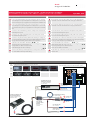
Montageanleitung für Leitungssatz „Stromanschluss Quadlok“
Installation instructions for “Power supply harness for Quadlok“
8J0 051 434
A
1 2 3 4 5
8 9 10 117 12
6
B
1 2 3 4 5
8 9 10 117 12
6
C
D
1
2
5
6
3 7
4 8
9
10
13
14
11 15
12 16
10
8J0 051 434
Stromanschluss
Quadlok
Power harness
Quadlok
Interface Audi Bluetooth
Freisprecheinrichtung
Interface Audi Bluetooth
Handsfree Unit
Quadlok Anschlussblock am Radio bzw. Navigationssystem
Quadlok multiway connector of radio/navigation system
Radiostumm-
schaltung D11
Radio mute D11
Radiostumm-
schaltung C10
Radio mute C10
rot: +12V (Kl. 30)
red: +12V (30)
+12V (Kl. 30)
+12V (30)
schwarz:Masse (Kl.31)
black: GND (31)
Masse (Kl.31)
GND (31)
blau: Zündungsplus (Kl.15)
blue: Ignition (15)
Zusatzadaptierung für
Radiomute verwenden
Use additional adapter
for radio mute
7
6
2
1
3
4
5
gelb
yellow
Pin Pinlayout Radiostummschaltung Pin layout radio mute
D11
RNS-E BNS 5.0 chorus II+ concert II+ symphony II+
C10
chorus III concert III symphony III

Original Zubehör
Audi
Abbildung Illustration
Änderungen vorbehalten. Subject to change without prior notice. Stand: 06/2010 © 2010 AUDI AG, Ingolstadt
Pin Signal Signal
C6 Telefon in + Phone-in +
C12 Telefon in – Phone-in –
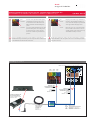
Montageschritte Installing the wiring harness
1
nicht
vorhanden
Verrasten Sie das grüne Kammergehäuse
des Leitungssatzes auf der unteren rechten
Position des Quadlok Verbinders am Radio/
Navigationssystem.
vorhanden Lösen Sie die beiden Einzelleitungen aus dem
grünen Kammergehäuse des Leitungssatzes
aus und verrasten Sie sie an der gleichen Posi-
tion des fahrzeugseitig vorhandenen grünen
Kammergehäuses.
1
non-
existent
Plug the green cage of the harness in the
Quadlok multiway connector of the radio/
navigation system at the lower right position.
existent Release the green cage´s two wires from the
harness and add the released wires to the
corresponding positions of the existing green
cage of the Quadlok multiway connector.
2
Stecken Sie den Klinkenstecker in die Lautsprecherbuchse am Interface der
Audi Bluetooth Freisprecheinrichtung ein. Die Lautsprecherbuchse befindet sich
neben der Mikrofonanschlussbuchse am Interface.
2
Plug the phone jack into the speaker connector from the interface of the Audi
Bluetooth Handsfree Unit. The speaker connector is located directly beside the
microphone connector.
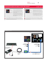
Montageanleitung für Leitungssatz „Telefonsignal Quadlok“
Installation instructions for “Phone-in harness for Quadlok“
8J0 051 434 A
A
1 2 3 4 5
8 9 10 117 12
6
B
1 2 3 4 5
8 9 10 117 12
6
C
D
1
2
5
6
3 7
4 8
9
10
13
14
11 15
12 16
10
8J0 051 434 A
Telefonsignal
Quadlok
Phone-in
Quadlok
Interface Audi Bluetooth
Freisprecheinrichtung
Interface Audi Bluetooth
Handsfree Unit
Quadlok Anschlussblock am Radio bzw. Navigationssystem
Quadlok multiway connector of radio/navigation system
Nur Fahrzeuge ohne
grünem Kammerstecker
am Quadlok Verbinder
Cars without
green cage in
Quadlok connector
NurFahrzeuge mit
grünem Kammerstecker
am Quadlok Verbinder
Cars with
green cage in
Quadlok connector
2
1
1
Pin Signal Signal
C6 Telefon in + Phone-in +
C12 Telefon in – Phone-in –

Original Zubehör
Audi
Abbildung Illustration
Änderungen vorbehalten. Subject to change without prior notice. Stand: 06/2010 © 2010 AUDI AG, Ingolstadt
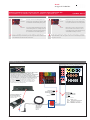
Montageschritte Installing the wiring harness
Der Leitungssatz „Y-Leitung Klemme 15“ ermöglicht den sicheren Anschluss an
Zündungsplus. Er wird in Fahrzeugen benötigt, bei denen fahrzeugseitig kein
S-Kontakt (86s) am Radio bzw. Navigationssystem liegt.
With the “Y-harness ignition signal“ you can connect the power harness to the
ignition signal. It is required in cars with no S-contact (86s) connected to the
radio/navigation system.
1
Schleifen Sie den Leitungssatz mit einem der beiden Steckereinsätze an eine
Sicherung „Zündungsplus (Klemme 15)“ ein.
1
Loop in the harness to a fuse holder for the ignition signal. Depending on the
connector type, use one of the two connectors from the harness.
2
Verrasten Sie den anderen, nicht verwendeten Steckeinsatz im entsprechenden
Gegengehäuse, um Kurzschlüsse zu vermeiden.
2
To prevent short circuits plug the unused connector into the corresponding
cage.
3
Verbinden Sie die Einzelleitung (Zündungsplus) über das 2-pol. Gehäuse der
“Y-Leitung Klemme 15“ mit der blauen Einzelleitung „Radiostummschaltung“
des Leitungssatzes Stromanschluss (8J0 051 434 / ..434 D).
3
Connect the wire (ignition signal) of the Y-harness with the blue wire “Radio
mute” of the power supply harness (8J0 051 434 / ..434 D).
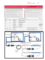
Montageanleitung für Leitungssatz „Y-Leitung Klemme 15“
Installation instructions for „Y-harness ignition signal“
8J0 051 434 B
8J0 051 434 B
Y-Leitung
Klemme 15
Y-harness
ignition signal
Nicht genutzten Anschluss in das Gegengehäuse
verrasten, um Kurzschlüsse zu vermeiden.
To prevent short circuits, plug any unused wire into
the corresponding cage.
zu Sicherung Zündungsplus (Kl. 15)
to fuse ignition signal (15)
zu Zündungsplus (Kl.15)
von Leitungssatz Stromanschluss
to Ignition (15) of power-harness
Zündungsplus (Kl.15)
Ignition (15)
Zündungsplus (Kl.15)
Ignition (15)
1
1
3
Leitungssatz 8J0 051 434
power harness 8J0 051 434
Leitungssatz 8J0 051 434 D
power harness 8J0 051 434 D
2
2
Pin 1
Pin 1
Fahrzeuge
vehicles
Sicherung Klemme 15 (Zündungsplus)
Fuse clamp 15 (ignition signal)
Einbauort
location
Produkt product Modell type Zeitraum period Mini ATO®
AU 34X A3 B1
bis MJ 2005
until MY 2005
Sicherung 5 Komfortelektronik etc.
fuse 5 comfort electronics etc.
Sicherungsträger
Schalttafel links
fuse holder dash
panel left
AU 34X TT 1
bis MJ 2006
until MY 2006
Sicherung 5 Komfortelektronik etc.
fuse 5 comfort electronics etc.
AU 35X A4 AB2
ab MJ 2003
from MY 2003
Sicherung 1 Diagnose
fuse 1 diagnosis
AU 32X TT 2
ab MJ 2007
from MY 2007
Sicherung 1 Diagnose
fuse 1 diagnosis
AU 46X A4 B6
bis MJ 2005
until MY 2005
Sicherung 5 Telefon
fuse 5 telephone
AU 47X A4 B7
ab/from MJ/MY 2006
bis/until MJ/MY 2008
Sicherung 5 Telefon
fuse 5 telephone
AU 48X / AU 416 A4 B8, A5, Q5
MJ 2009
MY 2009
Sicherungsträger A SW Sicherung 3 UGDO MJ 2009
fuse holder A SW fuse 3 UGDO MY 2009
AU 48X / AU 416 A4 B8, A5, Q5
ab MJ 2010
from MY 2010
Sicherungsträger A SW Sicherung 13 VDA MJ 2010
fuse holder A SW fuse 13 VDA MY 2010

Original Zubehör
Audi
Abbildung Illustration
Änderungen vorbehalten. Subject to change without prior notice. Stand: 06/2010 © 2010 AUDI AG, Ingolstadt
Montageschritte Installing the wiring harness
1
Nur bei Anschluss an Radios chorus I, concert I, symphony I:
Lösen Sie den Pin 1 (Radiostummschaltung, gelb) des schwarzen 8-fach
Gehäuses des Leitungssatzes aus und verrasten Sie die Leitung in Pin D1 am
DIN-ISO-Stecker des Radios. Das rote Steckgehäuse gehört zum Lieferumfang
des Leitungssatzes 8J0 051 434 F, bzw. das Einzelgehäuse ist unter der Teile-
nummer 357 035 447 B erhältlich.
1
Connection to radio systems chorus I, concert I and symphony I only:
Release pin 1 (radio mute, yellow) of the black 8-way connector of the harness
and connect it to pin 1 of the red 10-way connector of the DIN-ISO multiway
connector of the radio. The red cage is included in harness 8J0 051 434 F or is
available separately (Audi Part No. 357 035 447 B).
2
Lösen Sie das schwarze 8-pol. ISO-Gehäuse (A) aus dem DIN-ISO Verbinder am
Radio aus und verrasten Sie es in der 8-pol. Buchse des Leitungssatzes.
2
Release the black 8-way cage (A) from the DIN-ISO multiway connector and
plug it in the corresponding jack of the harness.
3
Stecken Sie das 8-pol. Steckergehäuse des Leitungssatzes an die Position A am
DIN-ISO Verbinder des Radios ein.
3
Connect the black 8-way cage of the harness to position A of the DIN-ISO
multiway connector.
4
Stecken Sie das weiße 4-pol. Kammergehäuse des Leitungssatzes in das Inter-
face der Audi Bluetooth Freisprecheinrichtung ein.
4
Plug the white cage of the harness into the interface of the Audi Bluetooth
Handsfree Unit.
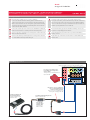
Montageanleitung für Leitungssatz „Stromanschluss DIN-ISO“
Installation instructions for “Power supply harness for DIN-ISO“
8J0 051 434 C
Sicherung
D
B
C 3C 2C 1
A
1
2
3
4
5
6
7
8
1
2
3
4
5
6
7
8
87
65
10
19
9
43
21
20
7 10
9 12
8 11
1 4
3 6
2 5
13 16
15 18
14 17
8J0 051 434 C
Stromanschluss
DIN-ISO (CAN)
Power harness
DIN-ISO (CAN)
Interface Audi Bluetooth
Freisprecheinrichtung
Interface Audi Bluetooth
Handsfree Unit
DIN-ISO Anschlussblock am Radio bzw. Navigationssystem
DIN-ISO multiway connector of radio/navigation system
Das 10-pol. rote Gehäuse ist im
Lieferumfang des Leitungssatzes
8J0 051 434 B
10-way red cage is included in harness
8J0 051 434 B
gelb: Radiostummschaltung (Kl.15)
yellow: radio mute (15)
4
1
2
3
Nur chorus I, concert I, symphony I:
Pin 1 aus dem Kammergehäuse
auslösen und in D1 verrasten.
chorus I, concert I, symphony I only:
Release pin 1 and plug it into D1.

Original Zubehör
Audi
Abbildung Illustration
Änderungen vorbehalten. Subject to change without prior notice. Stand: 06/2010 © 2010 AUDI AG, Ingolstadt
Montageschritte Installing the wiring harness
1
Verrasten Sie die gelbe Leitung des Leitungssatzes in Pin D1 am DIN-ISO-
Stecker des Radios. Das rote Steckgehäuse gehört zum Lieferumfang des Lei-
tungssatzes 8J0 051 434 F, bzw. das Einzelgehäuse ist unter der Teilenummer
357 035 447 B erhältlich.
1
Connect the yellow wire of the harness (radio mute) to pin 1 of the red 10-way
connector of the DIN-ISO multiway connector of the radio. The red cage is
included in harness 8J0 051 434 F or is available separately (Audi Part No. 357
035 447 B).
2
Verbinden Sie die schwarz/blaue Einzelleitung
des Leitungssatzes unter Verwendung der „Y-
Leitung Klemme 15“ (Abb. rechts, 8J0 051 434
B) mit Zündungsplus (Kl. 15) des Fahrzeugs.
2
Connect the black/blue wire of the harness
with the ignition signal (15) of the car. Use “Y-
harness for ignition signal“ (see illustration, Audi
Part No. 8J0 051 434 B) for installation.
3
Lösen Sie das schwarze 8-pol. ISO-Gehäuse (A) aus dem DIN-ISO Verbinder am
Radio aus und verrasten Sie es in der 8-pol. Buchse des Leitungssatzes.
3
Release the black 8-way cage (A) from the DIN-ISO multiway connector and
plug it into the corresponding jack of the harness.
4
Stecken Sie das 8-pol. Steckergehäuse des Leitungssatzes an die Position A am
DIN-ISO Verbinder des Radios.
4
Connect the black 8-way cage of the harness to position A of the DIN-ISO
multiway connector.
5
Stecken Sie das weiße 4-pol. Kammergehäuse des Leitungssatzes in das Inter-
face der Audi Bluetooth Freisprecheinrichtung ein.
5
Plug the white cage of the harness into the interface of the Audi Bluetooth
Handsfree Unit.
Montageanleitung für Leitungssatz „Stromanschluss DIN-ISO (CAN)“
Installation instructions for “Power supply harness for DIN-ISO (CAN)“
8J0 051 434 D
Sicherung
D
B
C 3C 2C 1
A
1
2
3
4
5
6
7
8
1
2
3
4
5
6
7
8
87
65
10
19
9
43
21
20
7 10
9 12
8 11
1 4
3 6
2 5
13 16
15 18
14 17
8J0 051 434 D
Stromanschluss
DIN-ISO (CAN)
Power harness
DIN-ISO (CAN)
Interface Audi Bluetooth
Freisprecheinrichtung
Interface Audi Bluetooth
Handsfree Unit
DIN-ISO Anschlussblock am Radio bzw. Navigationssystem
DIN-ISO multiway connector of radio/navigation system
Radiostumm-
schaltung D1
Radio mute D1
blau: Zündungsplus (Kl.15)
blue: Ignition (15)
5
gelb
yellow
1
3
4
Das 10-pol. rote Gehäuse ist im
Lieferumfang des Leitungssatzes
8J0 051 434 B
10-way red cage is included in harness
8J0 051 434 B
2
Leitungssatz 8J0 051 434 B
Y-harness 8J0 051 434 B

Original Zubehör
Audi
Abbildung Illustration
Änderungen vorbehalten. Subject to change without prior notice. Stand: 06/2010 © 2010 AUDI AG, Ingolstadt
Montageschritte Installing the wiring harness
1
nicht
vorhanden
Verrasten Sie die grün/blaue Kammergehäu-
sekombination des Leitungssatzes an der
oberen mittleren und rechten Position des
DIN-ISO Verbinders am Radio/Navigations-
system.
vorhanden Lösen Sie die beiden Einzelleitungen aus dem
grünen Kammergehäuse des Leitungssatzes
aus und verrasten Sie sie an der gleichen
Position des vorhandenen grünen Kammer-
gehäuses.
1
non-
existent
Plug the green and blue cage combination of
the harness into the DIN-ISO multiway con-
nector of the radio/navigation system located
at the upper middle and right positions.
existent Release the green cage´s two wires from the
harness. Add the released wires to the corre-
sponding positions of the existing green cage
of the DIN-ISO multiway connector.
2
Stecken Sie den Klinkenstecker in die Lautsprecherbuchse am Interface der
Audi Bluetooth Freisprecheinrichtung ein. Die Lautsprecherbuchse befindet sich
neben der Mikrofonanschlussbuchse am Interface.
2
Plug the phone jack into the speaker connector from the interface of the Audi
Bluetooth Handsfree Unit. The speaker connector is located directly beside the
microphone connector.
Montageanleitung für Leitungssatz „Telefonsignal DIN-ISO (C)“
Installation instructions for harness “Phone-in DIN-ISO (C)“
8J0 051 434 E
Sicherung
B
A
1
2
3
4
5
6
7
8
1
2
3
4
5
6
7
8
C 3C 2C 1
19
20
13 16
15 18
14 17
7 10
9 12
8 11
1 4
3 6
2 5
8J0 051 434 E
Telefonsignal
DIN-ISO (C)
Phone-in
DIN-ISO (C)
Interface Audi Bluetooth
Freisprecheinrichtung
Interface Audi Bluetooth
Handsfree Unit
DIN-ISO Anschlussblock am Radio bzw. Navigationssystem
DIN-ISO multiway connector of radio/navigation system
Fahrzeuge ohne
grünem Kammerstecker
am DIN-ISO Verbinder
Cars without
green cage in
DIN-ISO connector
Fahrzeuge mit
grünem Kammerstecker
am DIN-ISO Verbinder
Cars with
green cage in
DIN-ISO connector
2
gelb
yellow
grün
green
blau
blue
1
1
Pin Signal Signal
C7 Telefon in + Phone-in +
C12 Telefon in – Phone-in –

Original Zubehör
Audi
Abbildung Illustration
Änderungen vorbehalten. Subject to change without prior notice. Stand: 06/2010 © 2010 AUDI AG, Ingolstadt
Montageschritte Installing the wiring harness
1
nicht
vorhanden
Verrasten Sie das rote Kammergehäuse des
Leitungssatzes an der linken Position des DIN-
ISO Verbinders am Radio/Navigationssystem.
vorhanden Lösen Sie die beiden Einzelleitungen aus dem
roten Kammergehäuse des Leitungssatzes aus
und verrasten Sie sie an der gleichen Position
des vorhandenen roten Kammergehäuses.
1
non-
existent
Plug the red cage of the harness into the DIN-
ISO multiway connector of the radio/naviga-
tion system located at the outer left position.
existent Release the red cage´s two wires from the
harness. Add the released wires to the cor-
responding positions of the existing red cage
of the DIN-ISO multiway connector.
2
Stecken Sie den Klinkenstecker in die Lautsprecherbuchse am Interface der
Audi Bluetooth Freisprecheinrichtung ein. Die Lautsprecherbuchse befindet sich
neben der Mikrofonanschlussbuchse am Interface.
2
Plug the phone jack into the speaker connector from the interface of the Audi
Bluetooth Handsfree Unit. The speaker connector is located directly beside the
microphone connector.
Montageanleitung für Leitungssatz „Telefonsignal DIN-ISO (D)“
Installation instructions for harness “Phone-in Quadlok (D)“
8J0 051 434 F
Sicherung
D
B
C 3C 2C 1
A
1
2
3
4
5
6
7
8
1
2
3
4
5
6
7
8
87
65
10
19
9
43
21
20
7 10
9 12
8 11
1 4
3 6
2 5
13 16
15 18
14 17
8J0 051 434 F
Telefonsignal
DIN-ISO (D)
Phone-in
DIN-ISO
Interface Audi Bluetooth
Freisprecheinrichtung
Interface Audi Bluetooth
Handsfree Unit
DIN-ISO Anschlussblock am Radio bzw. Navigationssystem
DIN-ISO multiway connector of radio/navigation system
2
1
Nur für Fahrzeuge ohne Navigationssystem Low (BNS 3.x/4.x)
Ein vorhandenes rotes Kammergehäuse kann auf ein
vorhandenes Navigationssystem Low hindeuten. In Fahrzeugen
mit Navigationssystem Low nicht die Einzelleitungen des
Leitungssatzes in das vorhandene Steckergehäuse ergänzen, weil
dies zu Fehlfunktionen des Navigationssystems führen kann.
Only for cars without the navigationsystem low (BNS 3.x/4.x).
An existing red cage may indicate this navigation system.
In cars with navigation system low do not add the wires of
the harness to an exisiting red cage, since a malfunction
of the navigation system may result.
1
Fahrzeuge ohne
rotem Kammerstecker
am DIN-ISO Verbinder
Cars without
red cage in
DIN-ISO connector
Fahrzeuge mit
rotem Kammerstecker
am DIN-ISO Verbinder
Cars with
red cage in
DIN-ISO connector
Pin Signal Signal
D3 Telefon in + Phone-in +
D4 Telefon in – Phone-in –
-
 1
1
-
 2
2
-
 3
3
-
 4
4
-
 5
5
-
 6
6
-
 7
7


Audi 8J0 051 434 Installation Instructions Manual
- Typ
- Installation Instructions Manual
in anderen Sprachen
- English: Audi 8J0 051 434
Sonstige Unterlagen
-
Hama 00045782 Bedienungsanleitung
-
Caraudio Systems AUX-006 Installationsanleitung
-
-
Volkswagen 5NO 057342 Assembly Instructions Manual
-
-
-
-
 Mobridge Gateway Benutzerhandbuch
-
Manitowoc Ice INDIGO NXT Ice Machines Owner Instruction Manual
-
