
Gas Analysis
Installation and Operation Instructions
Original instructions
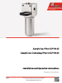
Sample Gas Filter AGF-VA-23
Sample Gas Coalescing Filter K-AGF-VA-23
BE410012
06/2019
Bühler Technologies GmbH, Harkortstr. 29, D-40880 Ratingen
Tel. +49 (0) 21 02 / 49 89-0, Fax: +49 (0) 21 02 / 49 89-20
E-Mail: [email protected]
Internet: www.buehler-technologies.com

Bühler Technologies GmbH, Harkortstr. 29, D-40880 Ratingen
Tel. +49 (0) 21 02 / 49 89-0, Fax: +49 (0) 21 02 / 49 89-20
Internet: www.buehler-technologies.com
E-Mail: [email protected]
Read this instruction carefully prior to installation and/or use. Pay at-
tention particularly to all advises and safety instructions to prevent in-
juries. Bühler Technologies can not be held responsible for misusing
the product or unreliable function due to unauthorised modifications.
All rights reserved. Bühler Technologies GmbH 2019
Document information
Document No...........................................................BE410012
Version.........................................................................06/2019

Sample Gas Coalescing Filter K-AGF-
VA-23
Contents
1 Introduction..................................................................................................................................................................................................................... 2
1.1 Intended Use.........................................................................................................................................................................................................2
1.2 Design types.......................................................................................................................................................................................................... 2
1.3 Scope of delivery.................................................................................................................................................................................................. 2
2 Safety instructions......................................................................................................................................................................................................... 3
2.1 Important notices................................................................................................................................................................................................ 3
2.2 General hazard warnings .................................................................................................................................................................................4
3 Use in explosive atmosphere areas .......................................................................................................................................................................... 5
4 Transport and storage .................................................................................................................................................................................................. 7
5 Installation and connection ........................................................................................................................................................................................8
5.1 Requirements to the installation site............................................................................................................................................................8
5.2 Connecting the gas lines...................................................................................................................................................................................8
5.3 Connecting a bypass or moisture detector..................................................................................................................................................8
6 Operation and control ..................................................................................................................................................................................................9
7 Maintenance.................................................................................................................................................................................................................. 10
7.1 Replacing the filter element........................................................................................................................................................................... 10
8 Service and repair.......................................................................................................................................................................................................... 11
8.1 Spare parts and accessories ............................................................................................................................................................................11
8.1.1 AGF-VA-23 ..............................................................................................................................................................................................11
8.1.2 K-AGF-VA-23 .........................................................................................................................................................................................12
9 Disposal............................................................................................................................................................................................................................13
10 Appendices..................................................................................................................................................................................................................... 14
10.1 Technical Data.................................................................................................................................................................................................... 14
10.2 Dimensions ..........................................................................................................................................................................................................15
10.3 List of chemical resistance .............................................................................................................................................................................. 16
11 Attached documents ....................................................................................................................................................................................................17
iBühler Technologies GmbHBE410012 ◦ 06/2019

Sample Gas Coalescing Filter K-AGF-
VA-23
1 Introduction
1.1 Intended Use
The filters may be used in a gas analysis system to filter sample gas.
Filters AGF-VA-23 and K-AGF-VA-23 may further be used in explosive atmosphere areas zone 1 and 2, explosion class IIA, IIB and
IIC. When used for this purpose, the information in chapter “
Use in explosive atmosphere areas
“ must be followed in addition to
the other information in these operating instructions.
1.2 Design types
If a filter type has special features, these are described separately in the operating manual. When connecting, please note the
specific values of the filter, and the correct version when ordering spare parts.
Please refer to the nameplate to identify your model. In addition to the job number it also contains the item number and model
designation.
The filters described here are based on the same gas connections and the same mounting diagram.
Filter type Description
AGF-VA-23-V Stainless steel filter with Viton / PVDF seal
AGF-VA-23-P Stainless steel filter with perfluoroelastomer seal
AGF-VA-23-V-F2/F25 Stainless steel filter with Viton / PVDF seal
AGF-VA-23-P-F2/F25 Stainless steel filter with perfluoroelastomer seal
K-AGF-VA-23-V Stainless steel coalescence filter with Viton / PVDF seal
K-AGF-VA-23-P Stainless steel coalescence filter with perfluorelastomer seal
Tab.1: Filter type overview
1.3 Scope of delivery
For AGF-VA-23:
– 1 x Filter
– Product Documentation
For K-AGF-VA-23:
– 1 x Filter
– 1x Filter element
– Product Documentation
2 Bühler Technologies GmbH BE410012 ◦ 06/2019

Sample Gas Coalescing Filter K-AGF-
VA-23
2 Safety instructions
2.1 Important notices
This unit may only be used if:
– The product is being used under the conditions described in the operating- and system instructions, used according to the
nameplate and for applications for which it is intended. Any unauthorized modifications of the device will void the warranty
provided by Bühler Technologies GmbH,
– The specifications and markings in the type plate are observed,
– The limits in the data sheet and the instructions must be observed,
– Monitoring equipment / protection devices must be connected correctly,
– Service and repair work not described in these instructions is performed by Bühler Technologies GmbH,
– Using genuine replacement parts.
Erecting electrical systems in explosive areas requires compliance with regulation EN 60079-14.
Additional national regulations pertaining to initial operation, operation, maintenance, repairs, and disposal must be observed.
These operating instructions are a part of the equipment. The manufacturer reserves the right to change performance-, specific-
ation- or technical data without prior notice. Please keep these instructions for future reference.
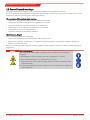
Signal words for warnings
DANGER
Signal word for an imminent danger with high risk, resulting in severe injuries or death if not avoided.
WARNING
Signal word for a hazardous situation with medium risk, possibly resulting in severe injuries or death if not
avoided.
CAUTION
Signal word for a hazardous situation with low risk, resulting in damaged to the device or the property or
minor or medium injuries if not avoided.
NOTICE
Signal word for important information to the product.
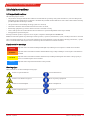
Warning signs
These instructions use the following warning signs:
Warns of a general hazard General information
Warns not to inhale toxic gasses Wear respiratory equipment
Warns of corrosive liquids Wear a safety mask
Warns of explosive areas Wear gloves
3Bühler Technologies GmbHBE410012 ◦ 06/2019

Sample Gas Coalescing Filter K-AGF-
VA-23
2.2 General hazard warnings
The equipment must be installed by a professional familiar with the safety requirements and risks.
Be sure to observe the safety regulations and generally applicable rules of technology relevant for the installation site. Prevent
malfunctions and avoid personal injuries and property damage.
The operator of the system must ensure:
– Safety notices and operating instructions are available and observed,
– The respective national accident prevention regulations are observed,
– The permissible data and operational conditions are maintained,
– Safety guards are used and mandatory maintenance is performed,
– Legal regulations are observed during disposal,
– compliance with national installation regulations.
Maintenance, Repair
Please note during maintenance and repairs:
– Repairs to the unit must be performed by Bühler authorised personnel.
– Only perform conversion-, maintenance or installation work described in these operating and installation instructions.
– Always use genuine spare parts.
Always observe the applicable safety and operating regulations in the respective country of use when performing any type of
maintenance.
DANGER Toxic, corrosive gases
The measuring gas led through the equipment can be hazardous when breathing or
touching it.
a) Check tightness of the measuring system before putting it into operation.
b) Take care that harmful gases are exhausted to a save place.
c) Before maintenance turn off the gas supply and make sure that it cannot be turned
on unintentionally.
d) Protect yourself during maintenance against toxic / corrosive gases. Use suitable pro-
tective equipment.
4 Bühler Technologies GmbH BE410012 ◦ 06/2019

Sample Gas Coalescing Filter K-AGF-
VA-23
3 Use in explosive atmosphere areas
Intended Use
Filters AGF-VA-23 and K-AGF-VA-23 may be used in explosive atmosphere areas zone 1 and 2. Explosion classes IIA, IIB and IIC are
approved. The filters have no innate ignition source and do not fall into the application of Directive 2014/34/EU and therefore do
not bear the CE mark.
II 2/2G c IIC TX X
, -5°C <T
amb
< +60 °C
The ambient temperatures must not be below -5°C or above 60°C.
The highest surface temperature is directly affected by the temperature of the medium introduced. The medium introduced
must not exceed the maximum temperature of 100°C. If necessary, a temperature monitor should be installed.
When operating the filters with moisture detector and controller, these must be inherently safe according to EN 60079-11.
When using a moisture detector, its working temperature may deviate from those specified here and limit the approved ambi-
ent temperature range of the filter as well as the permissible medium temperatures.
Depending on the process conditions, pressure- or flow sensors may be required for continuous monitoring. If the process holds
a risk of flame propagation a flame arrestor must be installed.
The approved explosion class of the inner zone varies by the filter element used. See chapter AGF-VA-23 [> page11] and K-AGF-
VA-23 [> page12] to match filter element options with explosion classes.
Safety instructions
The following safety notices must absolutely be followed when operating the filter in an area with explosive atmosphere. Fail-
ure to do so can result in an explosion hazard.
– Only perform installation-, removal- and maintenance work in non-explosive atmosphere.
– Protect filter from mechanical impact. If necessary, install a cover which withstands at least 4 joule.
– Protect filter from vibration, or avoid vibration. If necessary, mechanically brace supply and discharge lines.
– Observe all limits, operating parameters, etc. specified in these operating instructions and the data sheet.
– Maintenance and cleaning instructions must be followed.
– When used with moist gasses, a condensate separator must be installed. Moist gasses can clog pores in the filter. Gas pres-
sure building up can result in an impermissible temperature rise.
– Observe the grade of filtration of the fine mesh filter and if necessary install a pre-filtration to ensure larger solid particles do
not clog the filter prematurely.
– Observe the durability list in this document. Only use media compatible with the filter materials.
– Do not repair the filter. Damaged filter components must be replaced.
– Do not paint, laminate or otherwise coat the filters.
– Observe the applicable constructor regulations, e.g. EN 60079-14, for installation and mounting.
– All metallic parts of the filter must be connected to an earth potential. The resistance of a continuity test must not exceed 1
MΩ (1*10
6
Ω).
– The sealing materials, e.g. Teflon tape, must be conductive so all parts of the filter are earthed. If necessary, install an earth
bridge.
Operation and Control
DANGER Risk of explosive gasses leaking and crossing zones
Check the filter is tight prior to operation.
Inadequately sealed filters can leak. Gas may leak or the ambient atmosphere be drawn
in. Use a suitable method for the leakage test, appropriate for the application.
DANGER Explosion hazard due to isolated metal parts
Never operate the filter without the pressure spring in the base. If lost, the filter must be
taken out of service. Operation without the pressure spring poses an explosion hazard
and considered improper use.
5Bühler Technologies GmbHBE410012 ◦ 06/2019

Sample Gas Coalescing Filter K-AGF-
VA-23
Operation with moisture detector
DANGER Explosion hazard
To operate the filter in an explosive atmosphere with moisture detector, the moisture
detector and controller must be ignition protection class intrinsically safe “i”. The use of
non-intrinsically safe components may result in ignition in explosive atmospheres.
Also note the specifications under EN 60079-14 in this respect.
Service
Please note the following instructions. Failure to do so may result in explosive gasses escaping and crossing zones.
– Check the filter is tight after any maintenance and the intervals specified in the maintenance schedule. Inadequately sealed
filters can leak. Gas may leak or the ambient atmosphere be drawn in. Use a suitable method for the leakage test, appropri-
ate for the application.
– There must be no internal or external Ex atmosphere when performing maintenance. If necessary, flush the filter with inert
gas. Switch off pumps on the gas circuit and close supply and discharge lines.
– After performing any maintenance, before closing the filter be sure the pressure spring is installed inside the filter if previ-
ously removed, or is seated correctly.
Service schedule
When using the filters in ATEX areas, follow this maintenance schedule:
Component Interval in operating hours Work to be performed
Filter element Weekly, and depending on the contamination level
of the filter element.
– Visually inspect for contamination.
– If contaminated, replace the filter element and O-ring.
O-ring Every time the filter cover is removed. – Clean O-ring contact surfaces.
– Replace O-ring.
Entire filter Weekly and depending on the external level of con-
tamination.
– Remove layers of dust with a damp cloth.
Entire filter Every 6 months and every time the filter is opened. – Perform a leak test.
When replacing the filter element, the seal must also be replaced.
Cleaning
Dust deposits on the filter must be removed regularly.
Clean the outside of the filter using only a clean, damp cloth (do not use cleaners containing solvents).
DANGER Spark formation due to electrostatic discharge (explosion hazard)
Only clean the filter with a clean, damp cloth.
6 Bühler Technologies GmbH BE410012 ◦ 06/2019

Sample Gas Coalescing Filter K-AGF-
VA-23
4 Transport and storage
Only transport the product inside the original packaging or a suitable alternative.
The equipment must be protected from moisture and heat when not in use. It must be stored in a covered, dry and dust-free
room at a temperature of -20 °C to 60 °C (-4 °F to 140 °F).
7Bühler Technologies GmbHBE410012 ◦ 06/2019

Sample Gas Coalescing Filter K-AGF-
VA-23
5 Installation and connection
5.1 Requirements to the installation site
The filter should be installed in a way so the filter element can be replaced. If the filter protrudes from a contour, please note
this poses a risk of damage.
Mounting is done by two screws M5 in a distance of 35 mm (1.38 in).
The maximum pressure is 160 bar abs. for temperatures up to 140 °C (for restrictions see chapter „Connecting a bypass or mois-
ture detector [> page8]“).
5.2 Connecting the gas lines
The connections must be made carefully and properly using suitable fittings (gas connections right/left: G1/4; bottom condens-
ate drain: G3/8) and sealant.
When not using the condensate drain, attach a sealing plug to the thread (included).
An arrow on the filter indicates the flow direction. The head of the filters can be rotated to switch the inlet and outlet sides. Here
the included spacer block will be shifted accordingly.
Perform a leak test with suitable means.
5.3 Connecting a bypass or moisture detector
The filter head has a G1/4 female thread, factory sealed with a plug, for installing a bypass or moisture detector.
– To use the thread, unscrew the plug and screw in the fitting or model FF- moisture detector.
– Perform a leak test with suitable means.
CAUTION!With moisture detector the approved pressure is only 4 bar abs. and the maximum temperature 100 °C!
8 Bühler Technologies GmbH BE410012 ◦ 06/2019

Sample Gas Coalescing Filter K-AGF-
VA-23
6 Operation and control
NOTICE
The device must not be operated beyond its specifications.
9Bühler Technologies GmbHBE410012 ◦ 06/2019

Sample Gas Coalescing Filter K-AGF-
VA-23
7 Maintenance
During maintenance, remember:
– The equipment must be maintained by a professional familiar with the safety requirements and risks.
– Only perform maintenance work described in these operating and installation instructions.
– When performing maintenance of any type, observe the respective safety and operation regulations.
– Only perform maintenance when cool.
– For Ex applications also observe chapter “Use in explosive atmosphere areas”.
DANGER
The gas inside the filter, condensate and used filter elements may be caustic or corros-
ive.
Sample gas can be harmful.
a) Before maintenance turn off the gas supply and surge with air if necessary.
b) Exhaust sample gas to a safe place.
c) Protect yourself against toxic / corrosive gas during maintenance. Wear appropriate
personal protection equipment.
7.1 Replacing the filter element
CAUTION Gas leakage
The filter should not be dismantled under pressure.
Don’t use damaged parts again.
– Depressurise the system and flush the filter with air before opening.
– Pull the bracket, holding onto the filter cover.
– Slightly move the glass back and forth to carefully remove the cover downward.
– Remove the filter element and insert a new one.
– Check for leaks and replace, if necessary.
– Reattach the cover by slightly moving it back and forth and reattach the bracket. Ensure a proper fit.
– Perform a leak test with suitable means.
NOTICE!Please observe legal regulations when disposing of filter elements.
10 Bühler Technologies GmbH BE410012 ◦ 06/2019

Sample Gas Coalescing Filter K-AGF-
VA-23
8 Service and repair
This chapter contains information on troubleshooting and correction should an error occur during operation.
Repairs to the unit must be performed by Bühler authorised personnel.
Please contact our Service Department with any questions:
Tel.: +49-(0)2102-498955
or your agent
If the equipment is not functioning properly after correcting any malfunctions and switching on the power, it must be inspected
by the manufacturer. Please send the equipment inside suitable packaging to:
Bühler Technologies GmbH
- Reparatur/Service -
Harkortstraße 29
40880 Ratingen
Germany
Please also attach the completed and signed RMA decontamination statement to the packaging. We will otherwise be unable to
process your repair order.
You will find the form in the appendix of these instructions, or simply request it by e-mail:
.
8.1 Spare parts and accessories
Please also specify the model and serial number when ordering parts.
Upgrade and expansion parts can be found in our catalog.
Available spare parts:
8.1.1 AGF-VA-23
Filter (empty housing)
Item no. Model Seal
41 42 999 AGF-VA-23-V for installing DRG filter elements Viton
41 45 999 AGF-VA-23-P for installing DRG filter elements Perfluorelastomer
41 42 699 AGF-VA-23-V-F2/F25 for installing F2 / F25 filter elements Viton
41 45 699 AGF-VA-23-P-F2/F25 for installing F2 / F25 filter elements Perfluorelastomer
11Bühler Technologies GmbHBE410012 ◦ 06/2019

Sample Gas Coalescing Filter K-AGF-
VA-23
Filter elements
Item no. Model Seal Material Temperature
max.
Filter fineness Filter surface Packing
unit
Ex applic-
ation
78 56 966 DRG 25 VA-V Viton 1.4301 / epoxy resin 120 °C 25 µm 70 cm² 1 pieces IIC
78 56 974 DRG 60 VA-V Viton 1.4301 / epoxy resin 120 °C 60 µm 70 cm² 1 pieces IIC
78 56 982 DRG 100 VA-V Viton 1.4301 / epoxy resin 120 °C 100 µm 70 cm² 1 pieces IIC
41 03 003 DRG 25 SO-V Viton 1.4301 / 1.4401 150 °C 25 µm 70 cm² 1 pieces IIC
41 03 004 DRG 60 SO-V Viton 1.4301 / 1.4401 150 °C 60 µm 70 cm² 1 pieces IIC
41 03 008 DRG 25 SO-P Per-
fluoroelast-
omer
1.4301 / 1.4401 260 °C ** 25 µm 70 cm² 1 pieces IIC
41 03 009 DRG 60 SO-P Per-
fluoroelast-
omer
1.4301 / 1.4401 260 °C ** 60 µm 70 cm² 1 pieces IIC
41 03 00 50 F2 -- Sintered PTFE 100 °C 2 µm 60 cm² 5 pieces IIB
41 02 01 30 F25 -- Sintered PTFE 100 °C 25 µm 60 cm² 5 pieces IIB
41 28 008 Viton O-ring
(for filter…-V)
41 26 004 Perfluoroelast-
omer O-ring
(for filter…-P)
Other filter elements available upon request.
** at reduced maximum pressure.
8.1.2 K-AGF-VA-23
The filter includes a spacer block, 2 fixing bolts DN912M5x80, as well as sealing plugs inside the bypass and condensate out
connection.
Filter*
Item no. Model Seal
41 42 799 K-AGF-VA-23-V Viton
41 42 899 K-AGF-VA-23-P Perfluorelastomer
* one filter element is included with delivery.
Filter element
Item no. Model Filter element Material Filter surface Packing unit Ex application
49 32 001 12-57-C Sleeve Borosilicate fibre 28 cm² 1 pieces IIC
12 Bühler Technologies GmbH BE410012 ◦ 06/2019

Sample Gas Coalescing Filter K-AGF-
VA-23
9 Disposal
Dispose of parts so as not to endanger the health or environment. Follow the laws in the country of use for disposing of elec-
tronic components and devices during disposal.
13Bühler Technologies GmbHBE410012 ◦ 06/2019

Sample Gas Coalescing Filter K-AGF-
VA-23
10 Appendices
10.1 Technical Data
AGF-VA-23
AGF-VA-23 Fine Mesh Filter
Dead volume with filter element
DRGxxxSO-V/-P
DRGxxxVA-V
F2/F25
50 ml
56 ml
51 ml
Material - filter housing 1.4571 / SS 316 Ti
Material - gasket available in Viton or perfluorelastomer
Material - filter element see table
Weight 1.7 kg
Operating pressure max.* 160 bar
Medium temperature max.* see table
* Pressures and temperatures are greatly reduced when connecting a moisture detector.
K-AGF-VA-23
K-AGF-VA-23 Coalescence Filter
Dead volume with filter element 55 ml
Material - filter housing 1.4571 / SS 316 Ti
Material - gasket available in Viton or perfluorelastomer
Material - filter element see table
Weight 1.7 kg
Operating pressure max. 160 bar
Medium temperature max. 140 °C
14 Bühler Technologies GmbH BE410012 ◦ 06/2019

Sample Gas Coalescing Filter K-AGF-
VA-23
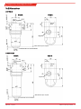
10.2 Dimensions
AGF-VA-23
View A
Bypass
IN
*NPT thread upon request
Spacer
block
View A
OUT
approx. 4
approx. 4
Bypass
Condensate out connections
K-AGF-VA-23
View A
Bypass
IN
*NPT thread upon request
Spacer
block
View A
OUT
approx. 4
approx. 4
Bypass
Condensate out connections
15Bühler Technologies GmbHBE410012 ◦ 06/2019

Sample Gas Coalescing Filter K-AGF-
VA-23
10.3 List of chemical resistance
Formula Substance Concentration Teflon®
PTFE
PVDF Viton®
FPM
CH
3
COCH
3
Acetone 1/1 3/4 4/4
C
6
H
6
Benzene 1/1 1/3 3/3
CI
2
Chlorine 10 % wet 1/1 2/2 3/0
CI
2
Chlorine 97 % 1/0 1/1 1/1
C
2
H
6
Ethane 1/0 2/0 1/0
C
2
H
5
OH Ethanol 50 % 1/1 1/1 2/2
C
2
H
4
Ethene 1/0 1/0 1/0
C
6
H
5
C
2
H
5
Ethylbenzene 1/0 1/1 2/0
HF Hydrofluoric acid 1/0 2/2 4/0
CO
2
Carbon dioxide 1/1 1/1 1/1
CO Carbon monoxide 1/0 1/1 1/0
CH
4
Methane technically pure 1/1 1/0 1/1
CH
3
OH Methanol 1/1 1/1 3/4
CH
3
CI
2
Methylene chloride 1/0 1/0 3/0
H
3
PO
4
Phosphoric acid 1-5 % 1/1 1/1 1/1
H
3
PO
4
Phosphoric acid 30 % 1/1 1/1 1/1
C
3
H
8
Propane gaseous 1/1 1/1 1/0
C
3
H
6
O Propenoxide 1/0 2/4 4/0
HNO
3
Nitric acid 1-10 % 1/1 1/1 1/1
HNO
3
Nitric acid 50 % 1/1 1/1 1/0
HCI Hydrochloric acid 1-5 % 1/1 1/1 1/1
HCI Hydrochloric acid 35 % 1/1 1/1 1/2
O
2
Oxygen 1/1 1/1 1/2
SF
6
Sulfur hexafluoride 1/0 0/0 2/0
H
2
SO
4
Sulfuric acid 1-6 % 1/1 1/1 1/1
H
2
S Hydrosulphide 1/1 1/1 4/4
N
2
Nitrogen 1/1 1/1 1/1
C
6
H
5
C
2
H
3
Styrene 1/1 1/0 3/0
C
6
H
5
CH
3
Toluene (Methylbenzene) 1/1 1/1 3/3
H
2
O Water 1/1 1/1 1/1
Tab.2: List of chemical resistance
0 - resistant
1 - practically resistant
2 - partially resistant
3 - not resistant
4 - no data available
Two values are given for each medium, left number = value at 20 °C (68 °F), right number = value at 50 °C (122 °F) Temperature.
Important note
The tables headed "Chemical resistance of plastics" and "Properties of plastics materials" have been compiled from information
from various producers of raw materials. The figures relate exclusively to laboratory tests on raw materials. Plastics items made
from these materials are often subject to influences which cannot be detected in a laboratory test (temperature, pressure,
stresses in the material, chemical substances, design features, etc.). For these reasons the figures quoted can serve only as a
guideline. In case of doubt we strongly recommend that a test be carried out. No legal claims can be derived from these figures
and we disclaim all liability. The chemical and mechanical resistance of a product does not suffice for the assessment of its suit-
ability for use, for example legislation on flammable liquids (explosion protection) is to be taken into particular consideration.
Chemical resistance for other substance on request.
16 Bühler Technologies GmbH BE410012 ◦ 06/2019

Sample Gas Coalescing Filter K-AGF-
VA-23
11 Attached documents
– Declaration of Conformity HX410010
– RMA - Decontamination Statement
17Bühler Technologies GmbHBE410012 ◦ 06/2019

Seite wird geladen ...
Seite wird geladen ...
-
 1
1
-
 2
2
-
 3
3
-
 4
4
-
 5
5
-
 6
6
-
 7
7
-
 8
8
-
 9
9
-
 10
10
-
 11
11
-
 12
12
-
 13
13
-
 14
14
-
 15
15
-
 16
16
-
 17
17
-
 18
18
-
 19
19
-
 20
20
-
 21
21
-
 22
22


Buhler AGF-VA-23 Installation And Operation Instruction Manual
- Typ
- Installation And Operation Instruction Manual
- Dieses Handbuch eignet sich auch für
in anderen Sprachen
- English: Buhler AGF-VA-23
Verwandte Artikel
-
Buhler Eco Installation And Operation Instructions Manual
-
-
-
-
-
-
-
-
-