
TEK
OPERATOR'S MANUAL
070-6738-00
-
-
-
-
-
-
-
-
-
-
-
-
-
-
--'
't
CFG250
FUNCTION
GENERATOR
COMMITTED
TO EXCELLENCE

TEK
070-6738-00
PRODUCT GROUP 46
-
-
CFG250
FUNCTION
GENERATOR
OPERATOR'S
MANUAL
Please Check for
CHANGE
INFORMATION
at the Rear
of
This Manual
First Printing November 1987
COMMITTED
TO
EXCElLENCE

Copyright © 1987 Tektronix, Inc. All rights reserved. Contents
of this publication
may
not
be
reproduced
in any
form
without
the written permission
of
Tektronix, Inc.
Products
of
Tektronix, Inc. and its subsidiaries are
covered
by
U.S. and foreign patents issued and pending.
TEKTRONIX, TEK, SCOPE-MOBILE,
a~d
i!
are registered
trademarks
of
Tektronix, Inc.
Printed
in
Hong Kong. Specification and price change privileges
are reserved.
INSTRUMENT SERIAL NUMBERS
Each
instrument
has a serial
number
on a panel insert, tag,
or
stamped
on the chassis. The first
number
or
letter designates
the
country
of
manufacture.
The last five digits
of
the serial
num-
ber
are assigned sequentially and are unique to each instru-
ment.
Those
manufactured
in
the United States have six unique
digits. The
country
of
manufacture
is identified as follows:
BOOOOOO
Tektronix,
Inc.,
Beaverton, Oregon,
U.S.A.
HK00001 Hong Kong
100000 Tektronix Guernsey,
Ltd.,
Channel Islands
200000 Tektronix United Kingdom,
Ltd.,
London
300000 Sony/Tektronix, Japan
700000 Tektronix Holland, NV, Heerenveen,
The Netherlands

-
Certificate
of
the Manufacturer/Importer
We
hereby certify that the
CFG250
FUNCTION
GENERATOR
AND
ALL
INSTALLED
OPTIONS
complies with the
RF
Interference Suppression requirements
of
Amtsbl.-Vfg 1046/1984.
The German Postal Service was notified that the equipment is being
marketed.
The German Postal Service has the right
to
re-test the series and to
verify that it complies.
TEKTRONIX
Bescheinigung des Herstellers/lmporteurs
Hiermit wird bescheinigt, daB der/die/das
CFG250
FUNCTION
GENERATOR
AND
ALL
INSTALLED
OPTIONS
in
Ubereinstimmung mit den Bestimmungen der Amtsblatt-Verfugung
1046/1984 funkentstort ist.
Der Deutschen Bundespost wurde das Inverkehrbringen dieses Gerates
angezeigt und die Berechtigung zur
UberprufUng der Serie auf Einhalten
der Bestimmungen eingeraumt.
TEKTRONIX

NOTICE to the user/operator:
The German Postal Service requires that Systems assembled
by
the
operator/user of this instrument must also comply with Postal
Regulation, Vfg. 1046/1984,
Par.
2,
Sect.
1.
HINWEIS
fUr
den Benutzer/Betreiber:
Die
vom Betreiber zusammengestellte Anlage, innerhalb derer dies
Gerat eingesetzt wird, muB ebenfalls den Voraussetzungen nach Par.
2,
Zift. 1 der Vfg. 1046/1984 genugen.
NOTICE to the user/operator:
The
German Postal Service requires that this equipment, when used
in
a
test setup, may only
be
operated if the requirements of Postal
Regulation, Vfg. 1046/1984,
Par.
2,
Sect.
1.7.1
are complied with.
HINWEIS
fUr
den Benutzer/Betreiber:
Dies
Gerat dart
in
MeBaufbauten nur betrieben werden, wenn die
Voraussetzungen des
Par.
2,
Zift.
1.7.1
der Vfg. 1046/1984 eingehalten
werden.

-
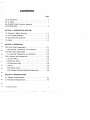
CONTENTS
Page
List of Illustrations
ii
List of Tables
ii
The CFG250 2 MHz Function Generator,
a brief description
iii
SECTION
1-PREPARATION
FOR USE
1.O-Operator's Safety Summary 1-1
1.1-Line
Voltage Selection
1-4
1.2-Grounding the Equipment
1-4
1.3-Fuses
. . . . . . . . .
..
1-4
SECTION
2-0PERATION
2.00-Front
Panel Organization 2-1
2.05-Controls,
Connectors, and Indicators
2-2
2.10-Rear
Panel Organization
2-4
2.
11-Controls
Connectors, and Indicators
2-5
2.20-Functions
and Applications
2-6
2.21-Sine
Wave
2-6
2.22-Square
Wave
2-7
2.23-Sawtooth
Wave
2-8
2.24-
TTL
2-9
2.25-Sweep
Output
2-9
2.26-Voltage
Controlled External Sweep Input
2-9
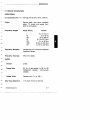
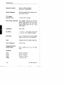
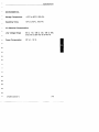
SECTION 3-SPECIFICATIONS
3.1-General Characteristics 3-1
3.2-Electrical
Characteristics
3-3
CFG250
Operator's

Page
SECTION
4-0PERATOR
MAINTENANCE
SECTION
5-BASIC
THEORY OF OPERATION
SECTION
6-GLOSSARY
OF
TERMS
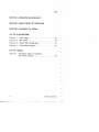
LIST OF ILLUSTRATIONS
Figure
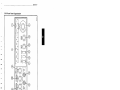
2-1.
Front Panel 2-1
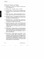
Figure
2-2.
Rear Panel
2-4
Figure
2-3.
Output Test Configuration
2-7
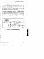
Figure
5-1.
Circuit Block Diagram 5-1
LIST OF TABLES
Table
2-1.
Waveform
chart
for
symmetry
and invert controls
2-3
ii
CFG250
Operator's

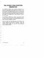
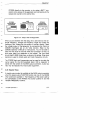
THE
CFG250
2
MHz
FUNCTION
GENERATOR
The TEKTRONIX CFG250 2 MHz
FUNCTION
GENERATOR
pro-
duces sine, square and sawtooth waves and
TTL
signals. Its ap-
plications include testing and calibration of audio, ultrasonic, and
servo systems. The CFG250's sweep function can be internally
controlled
or
controlled with an external
DC
level. Duty cycle,
DC
offset, sweep rate, sweep width and amplitude are controlled by
the operator. The CFG250 has an output
frequency
range of
0.2
Hz
to
2 MHz.
The TEKTRONIX CFG250 has a locking, multi-position handle
that folds under
the
instrument
to
allow stacking with other in-
struments
of
the
same
series. The instrument is delivered with a
power
cord
and an
Operator's
manual.
Should you need
more
information about your CFG250 2 MHz
Function Generator
or
other Tektronix products:
contact
the
nearest Tektronix Sales Office
or
Distributor, consult the
Tektronix
product
catalog,
or
in
the
U.S.,
call the Tektronix
National Marketing Center.
CFG250
Operator's
iii

SECTION
1
PREPARATION
FOR USE
CFG250
Operator'S

Preparation for
Use
OPERATOR'S
SAFETY
SUMMARY
The
general safety information in this
part
of
the
summary
is for
both operating
and
service personnel. Specific warnings and cau-
tions wili be found throughout the
manual
where they apply
and
do not appear in this summary.
Terms Used
In
This Manual
CAUTION
statements
identify conditions
or
practices that could
result in
damage
to
the
equipment
or
other property.
WARNING
statements
identify conditions
or
practices that could
result in personal injury
or
loss of life.
Terms
As
Marked
on
Equipment
CAUTION indicates a personal injury hazard that is not immedi-
ately accessible as one reads the markings.
or
a hazard
to
prop-
erty. including
the
equipment
itself.
DANGER
indicates a personal injury hazard immediately accessi-
ble as one reads the marking.
Symbols
In
This Manual
This symbol indicates where applicable cautionary
or
other
information is
to
be found.
CFG250
Operator's
1-1

Preparation for Use
Symbols
As
Marked
on
Equipment
~
DANGER
- High Voltage
@ Protective ground (earth) terminal.
A ATTENTION - Refer
to
Manual.
rh
Chassis ground.
Power Source
This
product
is intended
to
operate
from
a power source that
does not apply
more
than 250 volts
rms
between the supply con-
ductors
or
between either supply
conductor
and ground. A pro-
tective ground connection
by
way
of
the grounding
conductor
in
the power cord is essential
for
safe operation.
Grounding the Product
This
product
is grounded through the grounding
conductor
of the
power
cord.
To avoid electrical shock, plug the power cord into
a properly wired
receptacle
before
connecting
to
the product
input
or
output terminals. A protective ground connection by way
of the grounding
conductor
in
the power
cord
is essential for
safe operation.
Danger Arising From
Loss
of Ground
Upon loss of the
protective-ground
connection, all accessible
conductive parts (including knobs and controls that
may
appear
to be insulating) can render an electric shock.
1-2
CFG250
Operator's

Preparation for Use
Use
the
Proper
Power Cord
Use only the power cord and connector specified
for
your prod-
uct.
Use only a power cord that is
in
good condition.
For detailed information on power cords and connectors see
Figure
2-2.
Use
the
Proper
Fuse
To avoid fire hazard, use only a fuse of the
correct
voltage rating
and current rating as specified
in
the parts list
for
your product.
Do
Not Operate in Explosive
Atmospheres
To
avoid explosion, do not operate this product
in
an
explosive
atmosphere.
Do
Not
Remove
Covers
or
Panels
To
avoid personal injury, do not remove the product covers
or
panels.
Do
not operate the product without the covers and pan-
els properly installed.
CFG250
Operator's
1-3

Preparation for Use
1.1-Line
Voltage Selection
This product is intended
to
operate
from
a power source that
does not supply
more
than 250 V rms between the supply con-
ductors
or
between either supply conductor and ground. Normal
USA
voltage is 120 V AC. For line voltage selection setting, see
Figure
2-2.
1.2-Grounding the Equipment
A protective ground connection, the third wire
in
the power cord,
is necessary
for
safe operation. To avoid electrical shock, plug
the power cord into a properly wired receptacle before making
any connections to the equipment input
or
output terminals.
Do
not remove the ground lug from the power cord for any reason.
Use only the power cord and connector specified for this equip-
ment.
1.3-Fuses
To
avoid fire hazard, use only a fuse
of
the specified type, volt-
age rating and current rating
for
this equipment. (See 2.11 Con-
trols. Connectors. and Indicators.)
1-4
CFC250
Operator's

SECTION
2
OPERATION
CFG250
Operator'S
--~
~---

I 1
T=r=1
1=
I I I
()
"
G)
'"
01
0
0
"0
<ll
..,
III
0-
-:
'"
!!
CO
c:
...
CD,
IlioN
N
I
~
.
"
...
0
j
-
"'IJ
Q)
j
CD
1M
lOOK
10K
VOLTS
OUT
INVERT
SWEEP
100
10
t
--
13
l~FUNCTlON----,
ru
'V'.
"v
N
o
o
I
"
...
o
j
-
"'IJ
Q)
j
CD
o
...
co
Q)
j
~.
-
o·
j
I\)
I
......
6738·01
o
b
<D
Q)
i
6·
::J

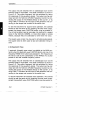
Operation
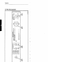
2.0S-Controls, Connectors, and Indicators
(1)
POWER
button - Push
in
to
turn CFG250 on. A second push
turns the generator off.
(2)
POWER
on light - Indicates a power on condition.
(3)
FUNCTION
buttons - The sine, square
or
sawtooth buttons
determine
the
type of signal provided at the
MAIN
output
connector.
(4)
RANGE
(Hz) buttons - These buttons determine the fre-
quency
range of the signal at the
MAIN
output connector.
(5)
FREQUENCY
control - This variable control determines the
frequency
of the signal at the
MAIN
output
connector
within
the range set by the
RANGE
buttons.
(6) AMPLITUDE control - This variable control, depending on
the position
of
the VOLTS
OUT
button, determines the level
of the signal at the
MAIN
output
connector.
(7) VOLTS
OUT
range button - Push in for
AMPLITUDE
control
range of
a
to
2
Vp-p,
open circuit,
or
a
to
1
Vp-p
into a 50
n load. Set
to
the out position
for
an
AMPLITUDE
control
range of
a
to
20
Vp-p,
in an open circuit,
or
a
to
10
Vp-p
to
a 50 n load.
(8)
INVERT
button - Pushing this button in causes the signal at
the MAIN output
connector
to
be inverted. When the
DUTY
control is being used, the invert switch determines which
half
of
the output
waveform
will be affected. Table 2-1
shows that relationship.
(9)
DUTY
control - Pull this control out
to
activate. At maxi-
mum
ccw
the output signal, including TTL, will be
symmetrical. Turning the control
cw
will change the period
of
half
the
waveform
as determined by the
INVERT
button.
The period of the unaffected half of the
waveform
will still
be
determined
by
the
FREQUENCY
multiplier and
RANGE
buttons. When the control is pushed in, the signal outputs
are symmetrical at all control settings.
2-2
---------
CFG250
Operator's

Operation
----------------_._---~
Table 2-1
Waveform
chart
for
symmetry
and
invert
controls
DUTY
eeN
DUTY
eN
Invert
Out
Invert
In
Invert
Out
Invert
In
Square
ru ru
LI
r-L-
-
Triangle
IV
IV
I---.
~
Sine
tV
tV
tV
tV
TTL
JLf
JLf
r-L-
LI
6738-03
(10)
DC
OFFSET - Pull this control out
to
activate. The
DC
OFF-
SET
control sets the
DC
level and polarity of the signal at
the MAIN output. When the control is pressed
in
the signal
is centered at zero Vdc.
(11)
SWEEP
button - Push in
for
internal sweep. This button
activates
the
sweep rate and sweep width controls. When
the button is
set
out
the
CFG250 will
accept
signals
from
its
EXTERNAL
SWEEP
input
connector
on the rear panel.
(12)
SWEEP
RATE
- This control adjusts the rate of the internal
sweep generator and the repetition rate of the burst gate.
(13)
SWEEP
WIDTH
- This control adjusts the amplitude of the
sweep.
(14)
MAIN
output
connector
-
BNC
output
connector
for
sine
wave, square wave and sawtooth wave signals.
~
The
outside (ground)
of
the MAIN and SYNC output con-
nectors are connected through the equipment
to
the
power source ground. Check the grounding system
of
the
receiving equipment before connecting the CFG250.
(15) SYNC (TTL) output
connector
-
BNC
output
connector
for
TTL
signals.
CFG250
Operator's
2-3

I\)
1
N
....
o
I
:D
CD
III
.,
~
(l)
~
-
O·
:::l
"
III
::J
CD
o
.,
10
III
:J
N"
III
-
o·
::J
@
6738-02
FUSE
RATING
100V2ASlOW
16
WATTS
120V
250V
20
VA
:_:~;~~~
~O
60Hl
®
~
<:----7
TEKTRONIX
INC
..
BEAVERTON
OR,
US,A
MADE
IN
TAIWAN
R.DC
CAUTION
TO
AVOIO
ELECTRIC
SHOCK.
THE
POWER
CORO
PROTECTIVE
GROUNDING
CONDUCTOR
MUST
BE
CONNECTED
TO
GROUND
00
NOT
REMOVE
COVERS
REFER
SERVICING
TO
QUALIFIED
PERSONNEL
@
100V
LINE
VOLTAGE
~
@
SELECT
VCF
,.-120V-,
® ®
tH~
(~
~n~~
§
~40~
"
III
:J
CD
:D
CD
III
.,
"'T1
!Co
c
.,
CD
N
I
N
()
""T1
G)
I\:>
01
Cl
o
"'0
CD
iil
0'
..,
'"

-
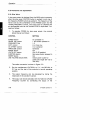
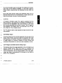
Operation
2.11-Controls, Connectors, Indicators
(1
R)
LINE
FUSE
- Provides protection
for
equipment malfunction
or
overload. (MOL
0.2
A, 250V
slow-blow
for
100-120
V
range
or
MOL
0.1 A, 250 V
slow-blow
for
220-240
V
range) .
(2R)
POWER
INPUT
- Input
connector
for
power
cord
- safety
coded.
(3R)
EXTERNAL
SWEEP
input
connector
- Input
BNC
connector
for
voltage-controlled
sweep. Signals applied
to
this
con-
nector
will control the output
frequency
when
the
SWEEP
button is set
to
the out position. An input
of
0
to
+1
OV
DC
sweeps the signal at the
MAIN
output down two decades
(100:1
).
The total sweep range is also dependent on the
base
frequency
and the desired sweep direction.
~
The
outside (ground)
of
the EXTERNAL SWEEP input
connector is connected through the equipment to the
power source ground. Check the grounding system
of
the
input equipment before connecting the CFG250.
(4R)
LINE
VOLTAGE SELECTOR - These selectors
connect
the
internal wiring
for
various line voltages.
~
Observe and set LINE VOLTAGE SELECTORs for the cor-
rect voltage level before operating the equipment.
CFG250 Operator's
2-5

Operation
2.20-Functions and Applications
2.21-Sine
Wave
A sine wave output is obtained
from
the
MAIN
output connector
when the sine wave
FUNCTION
button is pushed
in
and one of
the frequency
RANGE
buttons is pushed in. The frequency of the
wave is set
by
the combination of the
RANGE
button and the
variable
FREQUENCY
control. The output may be checked with
an
oscilloscope such as the Tektronix 2225
or
equivalent. Pro-
ceed as follows:
1. To operate CFG250
for
sine wave output, the controls
should be set as follows:
CONTROL
POWER
button
RANGE
(Hz) button
FREQUENCY
Dial
DUTY
control
DC
OFFSET
control
AMPLITUDE
control
INVERT
button
VOLTS
OUT
button
FUNCTION
button
SWEEP
button
LINE
VOLTAGE SELECTORs
SETTING
On
(pressed in)
1
KHz
button pressed
in
1.0
In
or
fully
ccw
In
or
centered
Centered
Out
Out
(0-20
position)
Sine wave button pressed
in
Out
Check power outlet
for
power line range (90-132
or
198-250).
The cable connection is shown
in
Figure
2-3.
2. Set the oscilloscope VOLTS/DIV to 2
V,
the SEC/DIV to
0.2
ms
and the rest
of
the controls to normal operating
position.
3. The output frequency can be calculated by taking the
reciprocal
of
the waveform period.
4. The output can be set precisely with the Tektronix CFC250
Frequency Counter
by
connecting the output of the
2-6
CFG250
Operator's
Seite wird geladen ...
Seite wird geladen ...
Seite wird geladen ...
Seite wird geladen ...
Seite wird geladen ...
Seite wird geladen ...
Seite wird geladen ...
Seite wird geladen ...
Seite wird geladen ...
Seite wird geladen ...
Seite wird geladen ...
Seite wird geladen ...
Seite wird geladen ...
Seite wird geladen ...
Seite wird geladen ...
Seite wird geladen ...
Seite wird geladen ...
-
 1
1
-
 2
2
-
 3
3
-
 4
4
-
 5
5
-
 6
6
-
 7
7
-
 8
8
-
 9
9
-
 10
10
-
 11
11
-
 12
12
-
 13
13
-
 14
14
-
 15
15
-
 16
16
-
 17
17
-
 18
18
-
 19
19
-
 20
20
-
 21
21
-
 22
22
-
 23
23
-
 24
24
-
 25
25
-
 26
26
-
 27
27
-
 28
28
-
 29
29
-
 30
30
-
 31
31
-
 32
32
-
 33
33
-
 34
34
-
 35
35
-
 36
36
-
 37
37


in anderen Sprachen
- English: Tektronix CFG250 User manual
Verwandte Artikel
Andere Dokumente
-
Wavetek 2C/3C Bedienungsanleitung
-
Amprobe FG2C-UA & FG3C-UA Function Generators Benutzerhandbuch
-
Aim-TTI TGF4042 Schnellstartanleitung
-
 METEX MS-9160 Bedienungsanleitung
-
Korg Poly Bedienungsanleitung
-
Samlexpower PST-300S-12E Bedienungsanleitung
-
Yamaha DX9 Bedienungsanleitung
-
-
Behringer ABACUS Schnellstartanleitung
-
VOLTCRAFT FG 250D Operating Instructions Manual
