
xx
P6245
1.5 GHz 10X Active Probe
*P070899505*
070-8995- 05
Instruction Manual
Manue l d’utilisation
Benutzerhandbuch
Manua l de instrucciones


P6245
1.5 GHz 10X Active Probe
ZZZ
Instruction Manual
xx
www.tektronix.com
070-8995-05

Copyright © Tektronix. All rights reserved. Licensed software products are
owned by Tektronix or its subsidiaries or suppliers, and are protected by
national copyri ght l aws and international treaty provisions.
Tektronix products are covered by U.S. and foreign patents, issued and
pending. Informati on in this publication supercedes that in all previously
published materi al. Specifications and price change privi leges reserved.
TEKTRONIX and TEK are registered trademarks of Tektronix, Inc.
Contacting Tektronix
Tektronix, Inc.
14200 SW Karl Braun Drive
P.O. Box 500
Beaverton, OR 97077
USA
For product information, sales, service, and technical support:
H In North America, ca ll 1-800-833-9200.
H Worldwide, visit www.tektronix.com to find contacts in your area.

Warranty
Tektronix warrants that this produ
ct w ill be free from defects in materials and
workmanship for a period of one (1) year from the date of shipment. If any such product
proves defective during this w
arranty period, Tektronix, at its option, either will repair
the defective product without charge for parts and labor, or w ill provide a replacement
in exchange for the defective
product. Parts, modules and replacement products used by
Tektronix for warranty work may be new or reconditioned to like new performance. All
replaced parts, modules and
products become the property of Tektronix.
In order to obtain service under this warranty, Customer must notify Tektronix of the
defect before the expiration of the warranty period and make suitable arrangements for the
performance of service. Customer shall be responsible for packaging and shipping the
defective product to the service center designated by Tektronix, with shipping charges
prepaid. Tektronix shall pay for the return of the product to Customer if the shipment is to
a location within t he country in which the Tektronix service center is located. Customer
shall be responsible for paying all shipping charges, duties, taxes, and any other charges
for products returned to any other locations.
This warranty shall not apply to any defect, failure or damage caused by improper use or
improper or inadequate maintenance a nd care. Tektronix shall not be obligated to furnish
service under this warranty a) to repair damage resulting from attempts by personnel other
than Tektronix representatives to install, repair or service the product; b) to repair damage
resulting from improper use or connection to incompatible equipment; c) to repair any
damage or malfunction c aused by the use of non-Tektronix supplies; or d) to service a
product that has been modified or integrated with other products w hen the effect of such
modification or integration increases the time or difficulty of servicing the product.
THIS WARRANTY IS GIVEN BY TEKTRONIX WITH RESPECT TO THE
PRODUCT I
N L IEU OF A NY OTHER WARRANTIES, EXPRESS OR IMPLIED.
TEKTRONIX AND ITS VENDORS DISCLAIM AN Y IMPLIED WARRANTIES OF
MERCHAN
TABILITY OR FITN ESS FOR A PARTICULAR PURPOSE. TEKTRONIX’
RESPONSIBILITY TO REPAIR OR REPLACE DEFECTIVE PRODUCTS IS THE
SOLE AN
D EXCLUSIVE REMEDY PROVIDED TO THE CUSTOMER FOR
BREACH OF THIS WARRANTY. TEK TRONIX AND ITS VENDORS W ILL NOT BE
LIABL
E FOR AN Y INDIRECT, SPECIAL, INCIDENTAL, OR CONSEQUENTIAL
DAMAGES IRRESPECTIVE OF WHETHER TEKTRONIX OR THE VEN DOR H AS
ADV
ANCE NOTICE OF THE POSSIBILITY OF SUCH DAMAGES.
[W2 – 15AUG04]


P6245 Instruction Manual
i
Table of Contents
Getting Started
Product Description 1--1.................................
Standard Accessories 1--1.................................
Customer Support 1--2...................................
Features and Accessories 1--3.............................
Configuration 1--7......................................
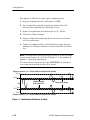
Probe Offset 1--7........................................
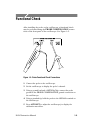
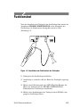
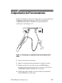
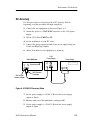
Functional Check 1--9...................................
Operating Basics
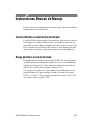
Operating Basics 2--1...................................
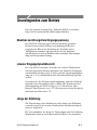
Maximum Non-destructive Input Voltage 2--1.................
Input Linear Dynami c Ra nge 2--1..........................
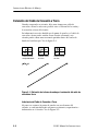
Ground Lead Length 2--2.................................
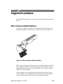
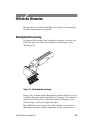
Helpful Hints 2--5......................................
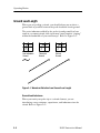
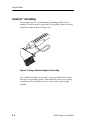
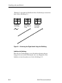
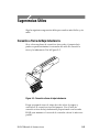
Low-inductance Grounding 2--5............................
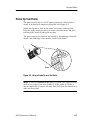
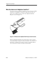
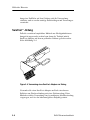
SureFoot™ Grounding 2--6................................
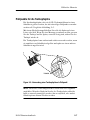
Probe Tip Test Points 2--7.................................
Probe Tip Stabilization 2--8...............................
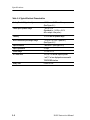
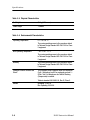
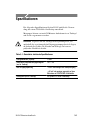
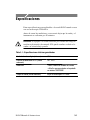
Specifications

Table of Contents
ii
P6245 Instruction Manual
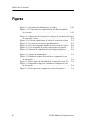
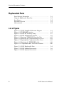
List of Figures
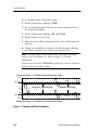
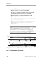
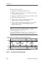
Figure 1 --1: Dynamic and Offset Limitations 1--8..............
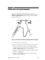
Figure 1--2: Probe Functional Check Connecti ons 1--9..........
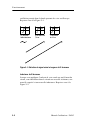
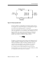
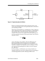
Figure 2--1: Wave form Distort ion from Ground Le ad Length 2--2.
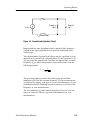
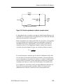
Figure 2--2: Ground Lead Equivalent Circ uit 2--3..............
Figure 2--3: Low-inductance Grounding 2--5..................
Figure 2--4: Using a SureFoot Adapter for Grounding 2--6.......
Figure 2--5: Using a Probe Tip as a Test Point 2--7.............
Figure 2 --6: Probe Tip Stabilizing Notch 2--8.................
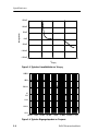
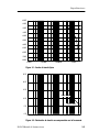
Figure 3--1: Typical Bandwidth 3--3.........................
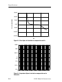
Figure 3--2: Typical Voltage Derating vs. Frequenc y 3--3........
Figure 3--3: Typic al Linearity Error vs VIN 3--4...............
Figure 3--4: Typical Input Impedance vs. Frequency 3--4........
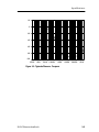
Figure 3--5: Typical Phase vs. Frequency 3--5.................

P6245 Instruction Manual
iii
General Safety Summary
Review the following safety precautions to avoid i njury and prevent
damage to this product or a ny products connected to it.
Only qualified personnel should perform service procedures.
Injury Precautions
Avoid Electric Overload
To avoid electric shock or fire hazard, do not apply a voltage to a
terminal that is outside the range specified for that terminal.
Do Not Operate Without Covers
To avoid electric shock or fire hazard, do not operate this product
with covers or panels remove d.
Do Not Operate in Wet/Damp Conditions
To avoid electric shock, do not operate this product in wet or damp
conditions.
Do Not Operate in Explosive Atmosphere
To avoid injury or fire hazard, do not operate this product in an
explosive atmosphere .

General Safety Summary
iv
P6245 Instruction Manual
Product Damage Precautions
Do Not Operate With Suspected Fai lures
If you suspect there is damage to this product, have it inspec ted by
qualified servic e pe rsonnel.
Do Not Immerse in Liquids
Clean the probe using only a damp cloth. Refer to cleaning
instructions.
Safety Terms and Symbols
Terms in This Manual
These terms may appear in this manual:
WARNING. Warning statements identify condit ions or practices that
could result in injury or loss of life.
CAUTION. Caution statements identify conditions or practices that
could result in damage to this product or other property.

P6245 Instruction Manual
v
Manual Organization
User Information
This section contains the information necessary to install and use the
P6245.
H Getting Started
This section contains the product description, description of
accessories, probe setup configuration, and how to check the probe
for normal operati on.
H Operating Basics
This section contains basic information and ope rating suggestions for
optimal probe performance
H Specifications
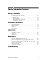
Service Information
This section contains the information necessary to maintain and
service the P6245.
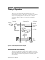
H Theory of Operation
H Performance Verification
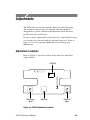
H Adjustments
H Maintenance
H Troubleshooting
Replaceable Parts List

Manual Organization
vi
P6245 Instruction Manual

Getting Started


P6245 Instruction Manual
1-1
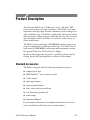
Product Description
The Tektronix P6245 is a 1.5 GHz (probe only), 10X active FET
probe with less than 1 pF input capacitance. The P6245’s low input
capacita nce and high input resistance minimize circuit loading over a
wide bandwidth range. The P6245’s small profile and low-mass head
makes probing crowded circuits by hand fast and easy. The accessory
tips and adapters ena ble the P6245 to be used on a wide variety of
circuit architectures.
The P6245 is powered through a TEKPROBE interface be tween the
probe’s compensation box and the oscilloscope. The P6245 may be
used with non-TEKPROBE oscilloscopes and instruments by using
the optional Tektronix 1103 Probe Power Supply.
In order to fully appreciate the probe’s capabilities, please read the
Getting Started and Operating Basics sections of this manual.
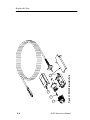
Standard Accessories
The P6245 is shipped with the following standa rd accessories:
H standard probe tips
H SMT KlipChip™ microcircuit test leads
H Y-lead adapter
H right-angle ada pter
H signal-ground adapters
H three- and six-inch ground l eads
H low-inductance ground lead
H marker rings
H Instruction Manual
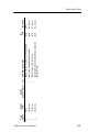
For part number information for standard and optional accessories,
refer to the Replaceable Parts section of this manual.

Product Description
1-2
P6245 Instruction Manual
Customer Support
To help you get the best performance from your probe, Tektronix
offers the following customer support services:
Operational Support
If you need assistance using your probe, please call our Custome r
Support Center at 1-800-TE K-WIDE (1-800-835-9433), e xtension
2400. If you are outside the United States or Canada, please contact
your nearest Tektronix Service Center.
Service Support
Should your probe need repair t hat is beyond that supported by this
manual, ple ase contact your nearest Tektronix Service Ce nter.
Sales Support
To order optional equipment and accessories, call the Tektronix
National Marketing Center at 1-800-426-2200. If you are outside the
United States or Canada , pl ease contact your nea rest Tektronix
Service Center.

P6245 Instruction Manual
1-3
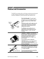
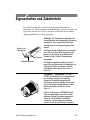
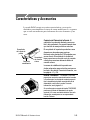
Features and Accessories
The P6245 is provided with several features and accessories designe d
to make probing and measurement a simpler task. Please take a
moment to familiarize yourself with the se items and their uses.
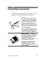
Probe Tip
Socket
Ground
Socket
Stabilization
Notch
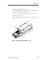
Probe Head Assembly. The probe head is
designed for ease of use and high performance.
Its small size makes it easy to handle in tight
areas.
The probe tip socket is sized to easily press onto
0.025 inch pins for direct access. The ground
socket provides a short ground path for high
fidelity ground connections.
The stabilization notch permits you to use
adjacent pins to reduce stresses on the probe
and pins. See pages 1--5 and 2--8 for more
information.
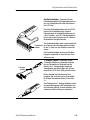
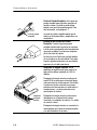
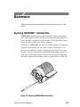
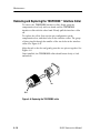
TEKPROBE™ Interface. The TEKPROBE
interface provides a communication path between
the probe and the oscilloscope. Contact pins
provide power, signal, offset, and probe
characteristic data transfer. See page 4--2 for
more information.
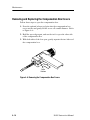
If your oscilloscope does not support the
TEKPROBE interface, you can use the optional
1103 probe power supply as an effective
interface. Contact your local Tektronix representa -
tive for more information.
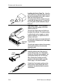
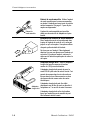
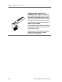
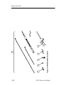
Push-In Probe Tip
Push-in Probe Tip. Use the push-in probe tip
for general purpose probing by hand. The tip may
also be used as a temporary test point. See page
2--7 for more information.
The push-in probe tip may also be used with the
other socketed leads and adapters.

Features and Accessories
1-4
P6245 Instruction Manual
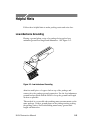
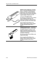
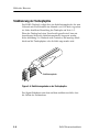
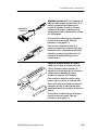
Installing the Push-in Probe Tip. Attach the
push-in probe tip by seating the tip into the probe
tip socket and pushing the tip in until it is seated.
Either end of the tip may be used.
Do not force the tip. Also, be careful not to poke
yourself with the sharp probe-tip. To remove the
tip, gently grab the tip with small pliers and pull
the tip out.
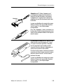
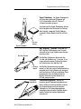
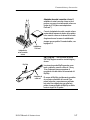
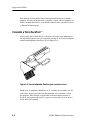
Right Angle
Adapter
Right-angle adapter. Use the right-angle
adapter for low-profile probing of 0.025 inch
diameter square pins.
The right-angle adapter allows the P6245 to lie
flat against a circuit board. This enables probing
in vertical circuits such as computer or commu-
nications backplanes, or in tight areas such as
between circuit cards.
The right-angle adapter can be used directly with
the probe head, or attached to the Y-lead adapter
or ground leads.
The right-angle adapter is attached the same way
as the push-in probe tip, and can be easily
removed by hand.
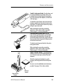
Y-lead
Adapter
“Y-lead” adapter. Use the Y-lead adapter to
extend the physical reach of the probe and
ground when necessary. The Y-lead adapter
accepts any of the probe tips or adapters, and
can be pushed directly onto 0.025 inch pins.
When selecting the grounding connection,
maintain as short a ground path as possible.
Refer to page 2--2 for more information.
To attach the Y-lead adapter, gently press the
lead pins into the probe head tip and ground
receptacles. Using the black lead for ground is
recommended.

Features and Accessories
P6245 Instruction Manual
1-5
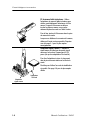
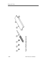
3 and 6 inch ground leads. Use the three- and
six-inch ground leads for general probing. The
socketed end of the leads may be connected to
any of the probe tips and adapters, or fitted onto
0.025 inch pins.
To attach the ground leads, press and rotate the
lead pin connector into the ground socket on the
probe head. The lead may be removed by simply
pulling the pin out by hand.
When selecting the grounding connection,
maintain as short a ground path as possible.
Refer to page 2--2 for more information.
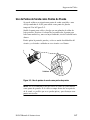
Low-inductance ground lead. Use the
low-inductance ground adapter to substantially
reduce ground lead inductance. Because the
ground lead simply touches the ground reference,
you can easily move the probe to different points
on the device under test.
To attach, press the ground lead into the probe
head gound socket.
When selecting the grounding connection,
maintain as short a ground path as possible.
Refer to page 2--2 for more information.
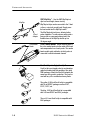
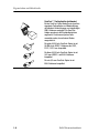
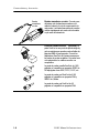
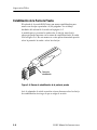
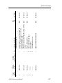
Signal Ground
Adapter
FlexLead
Adapter
Signal- Ground Adapter. The signal-ground
adapter is ideal for use with signal/ground pairs
on 0.100 inch header pins (such as FlexLead™
adapters).
Attach the signal-ground adapter by gently
pressing it into the ground socket on the probe
head.
Be sure to use the stabilization notch whenever
possible. See page 2-- 8 for further details.

Features and Accessories
1-6
P6245 Instruction Manual
KlipChip
Y-lead
Adapter
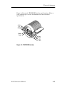
SMT KlipChip™. Use the SMT KlipChip test
clips to access fragile, dense circuitry.
KlipChip test clips can be connected to the Y-lead
or three- or six-inch ground leads. Simply press
the lead socket into the KlipChip handle.
The KlipChip body freely turns, allowing better
probe orientation. To reduce stress and provide a
lower profile on components being tested, the
flexible sleeve of the KlipChip bends up to a
35 degree angle.
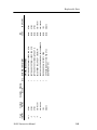
Color Marker
Bands
Color Marker Bands. Attach matching pairs of
the color marker bands onto the cable at the head
and compensation box of each probe. The marker
bands enable quick verification of which probe is
connected to which instrument channel.
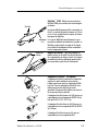
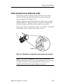
SureFoot™ probe tip (optional). The
SureFoot tip is an integral probe tip and miniature
guide that enables fault-free probing of fine-pitch
SMD packages. Attach the SureFoot adapters the
same way as the push-in probe tips. They can be
used with any of the socketed accessory leads.
The yellow, 0.050 inch SureFoot tip is compatible
with 50 mil JEDEC packages such as SOIC,
PLCC, CLCC, etc.
The blue, 0.025 inch SureFoot tip is compatible
with 0.65 mm JEDEC and EIAJ packages.
The red, 0.5 mm SureFoot tip is compatible with
EIAJ packages.
Seite wird geladen ...
Seite wird geladen ...
Seite wird geladen ...
Seite wird geladen ...
Seite wird geladen ...
Seite wird geladen ...
Seite wird geladen ...
Seite wird geladen ...
Seite wird geladen ...
Seite wird geladen ...
Seite wird geladen ...
Seite wird geladen ...
Seite wird geladen ...
Seite wird geladen ...
Seite wird geladen ...
Seite wird geladen ...
Seite wird geladen ...
Seite wird geladen ...
Seite wird geladen ...
Seite wird geladen ...
Seite wird geladen ...
Seite wird geladen ...
Seite wird geladen ...
Seite wird geladen ...
Seite wird geladen ...
Seite wird geladen ...
Seite wird geladen ...
Seite wird geladen ...
Seite wird geladen ...
Seite wird geladen ...
Seite wird geladen ...
Seite wird geladen ...
Seite wird geladen ...
Seite wird geladen ...
Seite wird geladen ...
Seite wird geladen ...
Seite wird geladen ...
Seite wird geladen ...
Seite wird geladen ...
Seite wird geladen ...
Seite wird geladen ...
Seite wird geladen ...
Seite wird geladen ...
Seite wird geladen ...
Seite wird geladen ...
Seite wird geladen ...
Seite wird geladen ...
Seite wird geladen ...
Seite wird geladen ...
Seite wird geladen ...
Seite wird geladen ...
Seite wird geladen ...
Seite wird geladen ...
Seite wird geladen ...
Seite wird geladen ...
Seite wird geladen ...
Seite wird geladen ...
Seite wird geladen ...
Seite wird geladen ...
Seite wird geladen ...
Seite wird geladen ...
Seite wird geladen ...
Seite wird geladen ...
Seite wird geladen ...
Seite wird geladen ...
Seite wird geladen ...
Seite wird geladen ...
Seite wird geladen ...
Seite wird geladen ...
Seite wird geladen ...
Seite wird geladen ...
Seite wird geladen ...
Seite wird geladen ...
Seite wird geladen ...
Seite wird geladen ...
Seite wird geladen ...
Seite wird geladen ...
Seite wird geladen ...
Seite wird geladen ...
Seite wird geladen ...
Seite wird geladen ...
Seite wird geladen ...
Seite wird geladen ...
Seite wird geladen ...
Seite wird geladen ...
Seite wird geladen ...
Seite wird geladen ...
Seite wird geladen ...
Seite wird geladen ...
Seite wird geladen ...
Seite wird geladen ...
Seite wird geladen ...
Seite wird geladen ...
Seite wird geladen ...
Seite wird geladen ...
Seite wird geladen ...
Seite wird geladen ...
Seite wird geladen ...
Seite wird geladen ...
Seite wird geladen ...
Seite wird geladen ...
Seite wird geladen ...
Seite wird geladen ...
Seite wird geladen ...
Seite wird geladen ...
Seite wird geladen ...
Seite wird geladen ...
Seite wird geladen ...
Seite wird geladen ...
Seite wird geladen ...
Seite wird geladen ...
Seite wird geladen ...
Seite wird geladen ...
Seite wird geladen ...
Seite wird geladen ...
Seite wird geladen ...
Seite wird geladen ...
Seite wird geladen ...
Seite wird geladen ...
Seite wird geladen ...
Seite wird geladen ...
Seite wird geladen ...
Seite wird geladen ...
Seite wird geladen ...
Seite wird geladen ...
Seite wird geladen ...
Seite wird geladen ...
Seite wird geladen ...
Seite wird geladen ...
Seite wird geladen ...
Seite wird geladen ...
Seite wird geladen ...
Seite wird geladen ...
Seite wird geladen ...
Seite wird geladen ...
Seite wird geladen ...
Seite wird geladen ...
Seite wird geladen ...
Seite wird geladen ...
Seite wird geladen ...
Seite wird geladen ...
Seite wird geladen ...
Seite wird geladen ...
Seite wird geladen ...
Seite wird geladen ...
Seite wird geladen ...
Seite wird geladen ...
Seite wird geladen ...
Seite wird geladen ...
Seite wird geladen ...
Seite wird geladen ...
Seite wird geladen ...
Seite wird geladen ...
Seite wird geladen ...
Seite wird geladen ...
Seite wird geladen ...
Seite wird geladen ...
Seite wird geladen ...
Seite wird geladen ...
Seite wird geladen ...
Seite wird geladen ...
Seite wird geladen ...
Seite wird geladen ...
Seite wird geladen ...
Seite wird geladen ...
Seite wird geladen ...
Seite wird geladen ...
Seite wird geladen ...
Seite wird geladen ...
Seite wird geladen ...
Seite wird geladen ...
Seite wird geladen ...
Seite wird geladen ...
Seite wird geladen ...
Seite wird geladen ...
Seite wird geladen ...
Seite wird geladen ...
Seite wird geladen ...
Seite wird geladen ...
Seite wird geladen ...
Seite wird geladen ...
Seite wird geladen ...
Seite wird geladen ...
Seite wird geladen ...
Seite wird geladen ...
Seite wird geladen ...
Seite wird geladen ...
Seite wird geladen ...
Seite wird geladen ...
Seite wird geladen ...
Seite wird geladen ...
Seite wird geladen ...
Seite wird geladen ...
Seite wird geladen ...
-
 1
1
-
 2
2
-
 3
3
-
 4
4
-
 5
5
-
 6
6
-
 7
7
-
 8
8
-
 9
9
-
 10
10
-
 11
11
-
 12
12
-
 13
13
-
 14
14
-
 15
15
-
 16
16
-
 17
17
-
 18
18
-
 19
19
-
 20
20
-
 21
21
-
 22
22
-
 23
23
-
 24
24
-
 25
25
-
 26
26
-
 27
27
-
 28
28
-
 29
29
-
 30
30
-
 31
31
-
 32
32
-
 33
33
-
 34
34
-
 35
35
-
 36
36
-
 37
37
-
 38
38
-
 39
39
-
 40
40
-
 41
41
-
 42
42
-
 43
43
-
 44
44
-
 45
45
-
 46
46
-
 47
47
-
 48
48
-
 49
49
-
 50
50
-
 51
51
-
 52
52
-
 53
53
-
 54
54
-
 55
55
-
 56
56
-
 57
57
-
 58
58
-
 59
59
-
 60
60
-
 61
61
-
 62
62
-
 63
63
-
 64
64
-
 65
65
-
 66
66
-
 67
67
-
 68
68
-
 69
69
-
 70
70
-
 71
71
-
 72
72
-
 73
73
-
 74
74
-
 75
75
-
 76
76
-
 77
77
-
 78
78
-
 79
79
-
 80
80
-
 81
81
-
 82
82
-
 83
83
-
 84
84
-
 85
85
-
 86
86
-
 87
87
-
 88
88
-
 89
89
-
 90
90
-
 91
91
-
 92
92
-
 93
93
-
 94
94
-
 95
95
-
 96
96
-
 97
97
-
 98
98
-
 99
99
-
 100
100
-
 101
101
-
 102
102
-
 103
103
-
 104
104
-
 105
105
-
 106
106
-
 107
107
-
 108
108
-
 109
109
-
 110
110
-
 111
111
-
 112
112
-
 113
113
-
 114
114
-
 115
115
-
 116
116
-
 117
117
-
 118
118
-
 119
119
-
 120
120
-
 121
121
-
 122
122
-
 123
123
-
 124
124
-
 125
125
-
 126
126
-
 127
127
-
 128
128
-
 129
129
-
 130
130
-
 131
131
-
 132
132
-
 133
133
-
 134
134
-
 135
135
-
 136
136
-
 137
137
-
 138
138
-
 139
139
-
 140
140
-
 141
141
-
 142
142
-
 143
143
-
 144
144
-
 145
145
-
 146
146
-
 147
147
-
 148
148
-
 149
149
-
 150
150
-
 151
151
-
 152
152
-
 153
153
-
 154
154
-
 155
155
-
 156
156
-
 157
157
-
 158
158
-
 159
159
-
 160
160
-
 161
161
-
 162
162
-
 163
163
-
 164
164
-
 165
165
-
 166
166
-
 167
167
-
 168
168
-
 169
169
-
 170
170
-
 171
171
-
 172
172
-
 173
173
-
 174
174
-
 175
175
-
 176
176
-
 177
177
-
 178
178
-
 179
179
-
 180
180
-
 181
181
-
 182
182
-
 183
183
-
 184
184
-
 185
185
-
 186
186
-
 187
187
-
 188
188
-
 189
189
-
 190
190
-
 191
191
-
 192
192
-
 193
193
-
 194
194
-
 195
195
-
 196
196
-
 197
197
-
 198
198
-
 199
199
-
 200
200
-
 201
201
-
 202
202
-
 203
203
-
 204
204
-
 205
205
-
 206
206
-
 207
207
-
 208
208
-
 209
209
-
 210
210
-
 211
211
-
 212
212
-
 213
213
-
 214
214


in anderen Sprachen
- English: Tektronix P6245 User manual
- français: Tektronix P6245 Manuel utilisateur
- español: Tektronix P6245 Manual de usuario
Verwandte Artikel
-
Tektronix P6245 Bedienungsanleitung
-
-
-
-
-
-
Tektronix TEKCHG-XX Bedienungsanleitung
-
Tektronix TDS3034C Bedienungsanleitung
-
-
Andere Dokumente
-
 Scientific TT-SX 200 Bedienungsanleitung
-
Omega OMSP-2000/3000/4000 Series Bedienungsanleitung
-
HAMEG HM-RTZP03 Bedienungsanleitung
-
PeakTech P 1286 Bedienungsanleitung
-
Extech Instruments TL620 Benutzerhandbuch
-
 PMK PHV622C Bedienungsanleitung
-
 Testec TS-HVP2739 Bedienungsanleitung
-
Extech Instruments MS6100 Benutzerhandbuch
-
 PMK MK881 Bedienungsanleitung
-
 PMK PMT221A Bedienungsanleitung


