Seite wird geladen ...

Instructions
P5210
High-Voltage Differential Probe
070-9841-00
1

Copyright Tektronix, Inc. All rights reserved.
Tektronix products are covered by U.S. and foreign patents, issued and
pending. Information in this publication supercedes that in all previously
published material. Specifications and price change privileges reserved.
Printed in the U.S.A.
Tektronix, Inc., P.O. Box 1000, Wilsonville, OR 97070–1000
TEKTRONIX, TEK, and TEKPROBE are registered trademarks of
Tektronix, Inc.

P5210 Instructions
1
Table of Contents
General Safety Summary 2. . . . . . . . . . . . . . . . . . . . . . . . . . . .
Getting Started 4. . . . . . . . . . . . . . . . . . . . . . . . . . . . . . . . . . . . .
Features and Accessories 4. . . . . . . . . . . . . . . . . . . . . . . . . . . . . .
Installation 10. . . . . . . . . . . . . . . . . . . . . . . . . . . . . . . . . . . . . . . . .
Functional Check 11. . . . . . . . . . . . . . . . . . . . . . . . . . . . . . . . . . . .
Operating Basics 12. . . . . . . . . . . . . . . . . . . . . . . . . . . . . . . . . . .
Operating the Probe Safely 12. . . . . . . . . . . . . . . . . . . . . . . . . . . .
Minimizing Risk of RF Burn (probe leads) 12. . . . . . . . . . . . .
Maximum Input Limits 12. . . . . . . . . . . . . . . . . . . . . . . . . . . .
Operating Characteristics and Probing Techniques 14. . . . . . . . . .
Operating Limits 14. . . . . . . . . . . . . . . . . . . . . . . . . . . . . . . . .
Overrange Detection 14. . . . . . . . . . . . . . . . . . . . . . . . . . . . . .
Common-Mode Rejection 14. . . . . . . . . . . . . . . . . . . . . . . . . .
Twisting the Input Leads 15. . . . . . . . . . . . . . . . . . . . . . . . . . .
Probe Loading 15. . . . . . . . . . . . . . . . . . . . . . . . . . . . . . . . . . .
Cleaning 16. . . . . . . . . . . . . . . . . . . . . . . . . . . . . . . . . . . . . . . . . . .
Specifications 17. . . . . . . . . . . . . . . . . . . . . . . . . . . . . . . . . . . . . .
Warranted Characteristics 17. . . . . . . . . . . . . . . . . . . . . . . . . . . . .
Typical Characteristics 20. . . . . . . . . . . . . . . . . . . . . . . . . . . . . . . .
Nominal Characteristics 23. . . . . . . . . . . . . . . . . . . . . . . . . . . . . . .

2
P5210 Instructions
General Safety Summary
Review the following safety precautions to avoid injury and prevent
damage to this product or any products connected to it.
Injury Precautions
Avoid Electric Overload. To avoid injury or fire hazard, do not apply
potential to any input, including the common inputs, that varies from
ground by more than the maximum rating for that input.
Avoid Electric Shock. To avoid injury or loss of life, connect the probe
output to a measurement instrument before connecting the test leads
to a voltage source. Do not disconnect the probe from the measure-
ment instrument while the test leads are connected to a voltage
source. Use only probe accessories that are rated for the application.
Avoid RF Burns While Handling Probe. To avoid RF burns, do not
handle the probe while the input leads are connected to circuits
above the voltage and frequency limits specified in Figure 2 on page
13. Use only probe accessories that are rated for the application.
Do Not Operate Without Covers. To avoid electric shock or fire hazard,
do not operate this product with covers or panels removed.
Do Not Operate in Wet/Damp Conditions. To avoid electric shock, do not
operate this product in wet or damp conditions.
Do Not Operate in an Explosive Atmosphere. To avoid injury or fire
hazard, do not operate this product in an explosive atmosphere.
Keep Probe Surface Clean and Dry. To avoid electric shock and
erroneous readings, keep probe surface clean and dry.
Product Damage Precautions
Do Not Operate With Suspected Failures. If you suspect there is damage
to this product, have it inspected by qualified service personnel.
Do Not Immerse in Liquids. Clean the probe using only a damp cloth.
Refer to the cleaning instructions on page 16.

General Safety Summary
P5210 Instructions
3
Safety Terms and Symbols
Terms in This Manual. These terms may appear in this manual:
WARNING. Warning statements identify conditions or practices that
could result in injury or loss of life.
CAUTION. Caution statements identify conditions or practices that
could result in damage to this product or other property.
Terms on the Product. These terms may appear on the product:
DANGER indicates an injury hazard immediately accessible as you
read the marking.
WARNING indicates an injury hazard not immediately accessible as
you read the marking.
CAUTION indicates a hazard to property including the product.
Symbols on the Product. These symbols may appear on the product:
Protective Ground
(Earth) Terminal
ATTENTION
Refer to Manual
Double
Insulated
DANGER
High Voltage
Certifications and Compliances
Refer to the specifications section for a listing of certifications and
compliances that apply to this product.

4
P5210 Instructions
Getting Started
This section describes the P5210 High-Voltage Differential Probe
and gives instructions on how to install and functionally test the
probe.
Features and Accessories
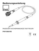
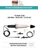
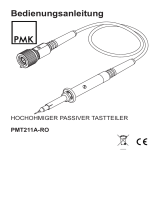
The P5210 probe (Figure 1) provides a safe means of measuring
circuits with floating high voltages. The probe outputs a low-voltage,
ground-referenced signal for display on instruments with the
TekProbe interface (or any oscilloscope or other measurement
instrument when used with the Tektronix 1103 TekProbe power
supply).
The P5210 probe allows clear and accurate measurements of
high-speed transitions and provides excellent rejection of common-
mode signals. Both inputs have high impedance and low capaci-
tance. Because of these features, the probe can safely and accurately
measure the fast voltage transients in switching power devices
without risk of damage.
Other applications for the P5210 probe include testing high-voltage
motor control circuits and line connected circuits in switch-mode
power supplies.
The probe has a number of design features to protect you from high
voltage. This protection extends up to the full input rating of the
probe.
The probe head and input cables are double insulated.
The control buttons and probe housing are non-conductive and
isolated.
The probe housing is internally shielded with a connection from
the shield to earth ground through the output cable.

Getting Started
P5210 Instructions
5
Figure 1: P5210 High-Voltage Differential Probe

Getting Started
6
P5210 Instructions
WARNING. To avoid shock or burn hazard, use only the standard
accessories or accessories that are rated for the application. Use the
P5210 accessories with this product only.
Keep your fingers behind the finger guard on the probe body
whenever possible to reduce the risk of a shock from the circuit under
test.
Differential Inputs. The inputs are CAT II rated to a
maximum of 2,200 V
RMS
between either input and
earth ground. They are also rated for a maximum
difference of 4,400 V
RMS
between the inputs with less
than 5,600 V
(DC
+
peak
AC)
) between the inputs or
between a single input and ground.
Attenuation Range. In the raised position the range
button sets the attenuation to 1,000X. In the lowered
position the range button sets the attenuation to 100X.
Use the 1,000X position for measurements up to a
maximum of 4,400 V
RMS
. Use the 100X position for
better signal resolution on connections below
440 V
RMS
.
Overrange Indicator. The overrange indicator lights red
if the voltage of the input signal exceeds the linear
operating range of the probe. When this happens, the
signal on the probe output does not accurately represent
the signal on the probe input.
Overrange Beeper. In the raised position the overrange
button sets the overrange beeper to sound whenever the
overrange indicator lights.
Bandwidth Select. In the raised position the bandwidth
button sets the full bandwidth (50 MHz). In the
lowered position the bandwidth is restricted to
approximately 5 MHz.

Getting Started
P5210 Instructions
7
Input Leads. The input leads of the differential probe
connect to the probe tips. The connectors are 4 mm
insulated banana plugs and are double insulated for
safety.
NOTE. Use only accessories that are rated to the
maximum input voltage under test.
TekProbe Interface. The TekProbe interface provides
power, signal, and probe characteristic data transfer.
If your oscilloscope does not support the TekProbe
interface, you can use the optional 1103 probe power
supply as an effective interface. Contact your local
Tektronix representative for more information.
Zero Adjust. Use the zero adjust to set the probe output
to the zero reference point prior to making measure-
ments. Use the adjustment tool provided.

Getting Started
8
P5210 Instructions
6-32 Probe Tip
Finger
Guard
Probe Body. The probe body is designed for personal
safety, ergonomic comfort, and signal fidelity. The
body is rated for the maximum input voltage of the
P5210 probe.
The probe tip is a 6–32 threaded post that accepts the
hook tips provided with the probe.
The finger guard provides protection when the hook
tips are not being used. Keep your fingers behind the
finger guard whenever possible to reduce the risk of a
shock from the circuit under test.
Use only accessories that are rated for the application.
Substitution of other accessories may create a shock or
burn hazard.
Keep the probe body and accessories clean to reduce
the risk of shock due to surface conduction. Refer to
page 16 for cleaning instructions.
Small Hook Tip. Use the small hook tip for making con-
nections to small conductors such as component leads.
The hook tip is rated for the maximum input voltage of
the P5210 probe.
Install the small hook tip by sliding it over the body of
the probe and screwing it onto the threaded probe tip
.
To use the tip, hold the probe body and pull the tip
shield back. Hook the tip onto the circuit and release
the shield.

Getting Started
P5210 Instructions
9
Large Hook Tip. Use the large hook tip when working
with larger components such as the bolt terminals and
bus bars typically found in power distribution equip-
ment. The hook tip is rated for the maximum input
voltage of the P5210 probe.
Install the large hook tip by sliding it over the body of
the probe and screwing it onto the threaded probe tip.
To use the tip, hold the probe body and pull the tip shield
back. Hook the tip onto the circuit and release the shield.
Soft Case. The soft case protects the probe and allows
you to hang the probe near the point of measurement.
Install or remove the case by opening the access flaps
on the back.
When not in use, coil the leads and secure them with
the strap on the back. Use one of the loops to hang the
probe on a storage hook or utility belt.
Color Marker Bands. When you are using more than one
probe, the bands enable you to quickly distinguish
between probes and the channels they are connected to.
To use the marker bands, attach one band near the
probe head and the matching band near the compensa-
tion box.
For a complete list of replaceable accessories and part ordering
information, refer to the service manual that accompanies this
product.

Getting Started
10
P5210 Instructions
Installation
Install the P5210 probe as follows:
1. Connect the output of the probe to the TekProbe input of the
oscilloscope or other measurement instrument. Make sure the
measurement instrument is properly grounded.
NOTE. Use the 1103 TekProbe Power supply if the instrument does
not have the TekProbe interface.
2. Select the proper range setting. For higher resolution and less
noise when measuring signals below 440 V
RMS
, switch the
attenuation to 100X. If the overrange indicator lights or flashes,
use the 1,000X setting or the output signal may not be accurate.
3. The probe output is adjusted to zero at the factory. Adjust the
probe output to zero only if you need to measure small
differential voltages. Follow steps a through c to make the
adjustment.
a. Let the probe warm up for at least 20 minutes.
b. Set the probe to the desired attenuation (100X or 1,000X)
c. Connect the input leads of the probe together. Insert the
adjustment tool in the access hole of the compensation
box and adjust the probe to the zero reference point.
If you are using this probe for the first time, read the General Safety
Summary on page 2 and Operating Basics on page 12 for important
safety information.

Getting Started
P5210 Instructions
11
Functional Check
To make a simple functional check of the P5210 probe, select a
source that supplies AC line voltage and use the following
procedure. This procedure verifies a majority of the circuitry within
the probe. (For a complete performance verification, refer to the
service manual that accompanies this product.)
1. Use the installation procedure starting on page 10 to connect the
output of the P5210 probe to a measurement instrument.
2. See Table 1 on page 11. Connect the inputs, set the range, and
perform the check as each line of Table 1 indicates.
Table 1: Functional Check
Mode
Range
Setting
Input 1
(+ or –)
Input 2
(– or +)
Check
Differential 100X or
1,000X
H
ot
Ground or
Neutral
Measurement instrument
displays or indicates the line
voltage
Common
Mode
100X or
1,000X
Hot (same
connection)
No signal
This completes the functional check procedure.

12
P5210 Instructions
Operating Basics
To help you use the P5210 High-Voltage Differential Probe safely
and effectively, this section provides important information about
safety limits, operating characteristics, and probing techniques.
Operating the Probe Safely
Before connecting the inputs of the probe to a circuit, read the safety
information in this section and attach the appropriate accessories to
the input connectors of the probe.
NOTE. To avoid shock or fire hazard, use only accessories that are
rated for the application.
Minimizing Risk of RF Burn (probe leads)
WARNING. To avoid personal injury, do not handle the probe leads
when the leads are connected to a source that is above the voltage
and frequency limits given in Figure 2 on page 13. The area above
these limits poses a risk of radio frequency (RF) burns.
If you need to use the probe within the risk area for RF burn, turn
power off to the source before connecting or disconnecting the probe
leads. Do not handle the input leads while the circuit is active.
Maximum Input Limits
To prevent damage to the probe, you must observe both the peak and
RMS ratings. (The rating for DC voltage is the same as the rating for
RMS voltage.) You must also observe the ratings between the
differential inputs and between each input and earth ground.

Operating Basics
P5210 Instructions
13
CAUTION. To avoid damaging the input circuitry of the P5210 probe,
do not apply voltage that is more than 2,200 V
RMS
between either
input and earth ground or more than 4,400 V
RMS
between the inputs.
In addition, the peak voltage must be less than 5,600 V
(DC
+
peak
AC)
between the inputs.
Above 1.5 MHz, the voltage limit decreases as frequency increases.
See Figure 2. The input limit applies to both the 100X and 1,000X
settings.
Voltage
(RMS)
1000V
100V
DC or 0 10M1M
Frequency (Hz)
5M 50M
500V
50V
100k 500k
Category II maximum
voltage limit (2,200 V)
RF burn risk area
(shaded)
Voltage derating
with frequency
4000V
Figure 2: Safety Limits (voltage between either input and earth ground)

Operating Basics
14
P5210 Instructions
Operating Characteristics and Probing Techniques
This section explains the operating characteristics of the P5210
High-Voltage Differential Probe along with techniques you can use
to maximize the performance of the probe.
Operating Limits
The P5210 probe has two operating ranges that you select with the
ATTENUATION button on the front panel: 1,000 X and 100X. These
ranges set the maximum differential voltage that can be measured.
In the 100X position, the probe can measure differential voltages
≤ 560 V
(DC
+
peak
AC)
.
In the 1,000X position, the probe can measure differential
voltages ≤ 5,600 V
(DC
+
peak
AC)
.
Always insure that the input voltages never exceed 2,200 V
RMS
from
either input to ground or 4,400 V
RMS
between the inputs.
Overrange Detection
Differential voltage outside the operating range will overdrive the
circuitry of the probe and distort the output signal. When this
differential overrange occurs, the probe detects the condition and
lights the overrange indicator. With the Audible Overrange ON, the
probe will also emit an audible alarm.
NOTE. Common-mode voltage greater than 2,200 V can distort the
output signal, but the probe will not indicate an overrange condition.
Common-Mode Rejection
The common-mode rejection ratio (CMRR) is the specified ability of
P5210 probe to reject signals that are common to both inputs. More
precisely, CMRR is the ratio of the differential gain to the common-
mode gain. The higher the ratio, the greater the ability of probe to
reject common-mode signals. For detailed specifications, see
pages 17 and 20.

Operating Basics
P5210 Instructions
15
Common mode rejection decreases as the input frequency increases.
Figure 4 on page 21 is a plot of typical CMRR of the probe versus
input frequency. For example, if you apply a 60 Hz line voltage of
500 V
P-P
to both input leads of the probe, the probe rejects the signal
by 80 dB (typical) and the signal appears as only a 50 mV
P-P
signal
on the oscilloscope screen.
Twisting the Input Leads
Twisting the input leads as shown in Figure 3 helps to cancel noise
that is induced into the input leads and to improve the high-frequen-
cy response of the inputs.
Figure 3: Twisting the Input Leads
Probe Loading
When you touch your probe tip to a circuit element, you are
introducing a new resistance, capacitance, and inductance into the
circuit.
Frequency and impedance of the source determine how much the
probe loads the circuit you are measuring. As the frequency of the
source starts to increase beyond 1 kHz, the input impedance of the
probe begins to decrease. The lower the impedance of the probe
relative to that of the source, the more the probe loads the circuit
under test. For a graph of frequency versus input impedance, refer to
Figure 5 on page 22. As the graph shows, the probe has virtually no
loading effect on sources with relatively low impedance and low
frequency.

Operating Basics
16
P5210 Instructions
Cleaning
Remove dirt with a soft cloth dampened in a mild detergent and
water solution or isopropyl alcohol.
CAUTION. To avoid damaging the probe, use only a mild detergent
and water solution or isopropyl alcohol, do not use any other
solvents or abrasive cleaners. Do not immerse the probe.

P5210 Instructions
17
Specifications
The specifications in Tables 2 through 6 apply to a P5210 probe
installed on a Tektronix TDS 460A oscilloscope. When the probe is
used with another oscilloscope, the oscilloscope must have an input
impedance of 1 MW and a bandwidth greater than 200 MHz.
The probe must have a warm-up period of at least 20 minutes and be
in an environment that does not exceed the limits described in
Table 2.
Specifications for the P5210 probe fall into three categories:
warranted, typical, and nominal characteristics.
Warranted Characteristics
Warranted characteristics (Tables 2 and 3) describe guaranteed
performance within tolerance limits or certain type-tested require-
ments. Warranted characteristics that have checks in the Perfor-
mance Verification procedure appear in boldface type. The
Performance Verification procedure appears in the P5210 Service
Manual (070-9895-XX, English only).
Table 2: Warranted Electrical Characteristics
DC Common Mode Rejection Ratio
> 3000:1 at 500 VDC, 20–30_ C, <70% RH
Bandwidth DC to 50 MHz (–3dB)
Gain Accuracy
± 3% at 20–30_ C, <70% RH

Specifications
18
P5210 Instructions
Table 2: Warranted Electrical Characteristics (Cont.)
Max
im
u
m
r
a
te
d
i
n
p
u
t
volt
ag
e
(Refer to Figure 2 on page 13)
probe tip to probe tip
4.4 kV
RMS
1
, Category I & II
k
S
1
, C te or III
probe tip to earth
1
k
V
RM
S
1
,
C
a
te
g
or
y
III
5.6 kV
(DC
+
peak
AC)
2
2.2 kV
RMS
1
, Category I & II
1 kV
RMS
1
, Category III
Temperature
3
Operating: 0 to 40_ C
Nonoperating: –30 to +70_ C
Humidity
3
Operating: <85% RH at or below +35_ C
Nonoperating: <85% RH at or below
+60_ C
1
The rating for DC voltage is the same as the rating for RMS voltage.
2
The input voltage must not exceed this peak rating or the RMS rating.
3
Tektronix Design Standard 062-2847-00
/