

CONTENTS
Quick Guide in English ......................................................................................................................... 2
Guide Succinct en Français ................................................................................................................ 43
Kurzanleitung..................................................................................................................................... 83
Guida Rapida in Italiano ................................................................................................................... 123
G ................................................................................................................... 163
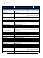
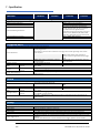
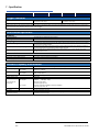
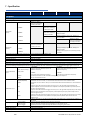
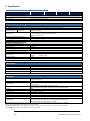
Specification .................................................................................................................................... 203

0 - Table of Contents
2 TGF4000 Series Quick Start Guide
TABLE OF CONTENTS
Introduction ................................................................................................................................................. 3
The TGF4000 Series of Arbitrary Function Generators ...................................................................................... 3
About this Guide ............................................................................................................................................... 3
Safety ........................................................................................................................................................... 4
General .............................................................................................................................................................. 4
Symbols ............................................................................................................................................................. 5
Operational Principles .................................................................................................................................. 6
Front Panel Layout ............................................................................................................................................ 6
Rear Panel Layout .............................................................................................................................................. 7
Screen Layout .................................................................................................................................................... 8
Getting Started ............................................................................................................................................. 9
Basic Set-up Examples ................................................................................................................................ 10
Setting-up a Sine Wave Signal ......................................................................................................................... 10
Setting-up a Square Wave Clock Signal ........................................................................................................... 14
Setting-up a Pulse Waveform .......................................................................................................................... 20
Setting-up more Output Options .................................................................................................................... 28
Requirement ................................................................................................................................................... 28
Exploring the Generator Capabilities .......................................................................................................... 32
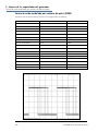
Setting-up an arbitrary wave signal ................................................................................................................. 32
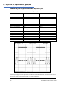
Setting-up an AM modulated Sine Waveform ................................................................................................. 33
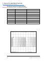
PRBS ................................................................................................................................................................ 34
Frequency Modulation of a Sine Waveform .................................................................................................... 35
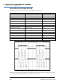
Pulse Width Modulated Waveform (PWM) ..................................................................................................... 36
Amplitude shift keying (ASK) ........................................................................................................................... 37
Frequency Sweep of a Sine Wave .................................................................................................................... 38
Generating a Triggered Burst........................................................................................................................... 39
Coupling the Frequency of Both Channels ...................................................................................................... 40
Frequency counter .......................................................................................................................................... 41
Maintenance .............................................................................................................................................. 42
Cleaning .......................................................................................................................................................... 42
The latest revisions of this manual, device drivers and software tools can be downloaded from:
http://www.aimtti.com/support

1 - Introduction
The TGF4000 Series of Arbitrary Function Generators
3 TGF4000 Series Quick Start Guide
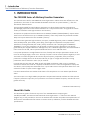
1. INTRODUCTION
The TGF4000 Series of Arbitrary Function Generators
This manual covers all four TGF4000 dual channel generators. Where there are differences in the
specification, the limits for the TGF4042 & TGF4082 are shown in square brackets [ ] after the
TGF4162 & TGF4242 limits.
These programmable function/arbitrary generators use direct digital synthesis techniques to
provide high performance and extensive facilities in a compact instrument. They generate a wide
variety of waveforms with high resolution and accuracy.
Sine waves are produced with low distortion to 160MHz/240MHz [40MHz/80MHz]. Square waves
have fast rise and fall times at up to 100MHz [25MHz]. Linear ramp waves are produced to 5MHz.
Ramp and square waves also have variable symmetry.
The instruments generate high resolution, low jitter, variable edge time pulses to 100MHz [25MHz]
with variable period, pulse width, pulse delay, pulse edges and amplitude. Complex custom
waveforms can be generated with 16-bit [14-bit] resolution and a sampling rate of 800MSa/s
[400MSa/s]. Up to four waveforms can be stored in internal memory. Waveforms can also be
generated by the supplied Waveform Manager Plus V4.13 Windows application and downloaded to
the instrument via USB, LAN or optional GPIB interfaces or via a USB flash drive.
Front panel operation is straightforward and user friendly with all major parameters shown at all
times on the large, bright, colour LCD. All major functions can be accessed with a single key or two.
The knob or numeric keypad can be used to adjust frequency, amplitude, offset, and other
parameters. Voltage values can be entered directly in Vpp or as high and low levels. Timing
parameters can be entered in Hertz (Hz) or seconds.
Internal AM, FM, PM, ASK, FSK, BPSK, SUM* and PWM modulation make it easy to modulate
waveforms without the need for a separate modulation source. Linear and logarithmic sweeps are
also built in, with sweep rates selectable from 1 µs to 500s. Burst mode operation allows for a user-
selected number of cycles at each trigger event.
LAN and USB interfaces are standard and there is full compliance to 1.5 LXI Device Specification
2016.
The instruments use a high stability temperature compensated internal oscillator and the external
frequency reference input lets you synchronize to an external 10 MHz frequency standard for even
greater accuracy.
*TGF4162 & TGF4242 only
About this Guide
This Quick Start guide is for bench-top use of the TGF4000 Series comprising the
TGF4042,TGF4082, TGF4162 and TGF4242 dual channel generators. A full Instruction Manual
(English only) is also provided on the Aim-TTi website that includes comprehensive explanations of
all functions and additional information on remote control, calibration, and the detailed technical
specifications.

2 - Safety
General
4 TGF4000 Series Quick Start Guide
2. SAFETY
General
This generator is a Safety Class I instrument according to IEC classification and has been designed to
meet the requirements of EN61010−1 (Safety Requirements for Electrical Equipment for
Measurement, Control and Laboratory Use). It is an Installation Category II instrument intended for
operation from a normal single phase supply.
This instrument has been tested in accordance with EN61010−1 and has been supplied in a safe
condition. This instruction manual contains some information and warnings which have to be
followed by the user to ensure safe operation and to retain the instrument in a safe condition.
This instrument has been designed for indoor use in a Pollution Degree 2 environment in the
temperature range 5°C to 40°C, 20% − 80% RH (non−condensing). It may occasionally be subjected
to temperatures between +5° and −10°C without degradation of its safety. Do not operate while
condensation is present.
Use of this instrument in a manner not specified by these instructions may impair the safety
protection provided. Do not operate the instrument outside its rated supply voltages or
environmental range.
WARNING! THIS INSTRUMENT MUST BE EARTHED
Any interruption of the mains earth conductor inside or outside the instrument will make the
instrument dangerous. Intentional interruption is prohibited. The protective action must not be
negated by the use of an extension cord without a protective conductor.
When the instrument is connected to its supply, terminals may be live and opening the covers or
removal of parts (except those to which access can be gained by hand) is likely to expose live parts.
The apparatus shall be disconnected from all voltage sources before it is opened for any
adjustment, replacement, maintenance or repair. Any adjustment, maintenance and repair of the
opened instrument under voltage shall be avoided as far as possible and, if inevitable, shall be
carried out only by a skilled person who is aware of the hazard involved.
If the instrument is clearly defective, has been subject to mechanical damage, excessive moisture
or chemical corrosion the safety protection may be impaired and the apparatus should be
withdrawn from use and returned for checking and repair.
Make sure that only fuses with the required rated current and of the specified type are used for
replacement. The use of makeshift fuses and the short−circuiting of fuse holders is prohibited.
This instrument uses a Lithium button cell for non−volatile memory battery back−up; typical life is
5 years. In the event of replacement becoming necessary, replace only with a cell of the correct
type, i.e. 3V Li/Mn0
2
20mm button cell type 2032. Exhausted cells must be disposed of carefully in
accordance with local regulations; do not cut open, incinerate, expose to temperatures above 60°C
or attempt to recharge.
Do not wet the instrument when cleaning it and in particular use only a soft dry cloth to clean the
LCD window.

2 - Safety
Symbols
5 TGF4000 Series Quick Start Guide
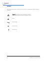
Symbols
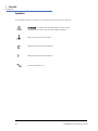
The following symbols are used on the instrument and in this manual:
Caution
−refer to the accompanying documentation,
incorrect operation may damage the instrument.
Terminal connected to chassis ground.
Mains supply OFF.
l
Mains supply ON.
Alternating current.

3 - Operational Principles
Front Panel Layout
6 TGF4000 Series Quick Start Guide
3. OPERATIONAL PRINCIPLES
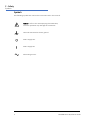
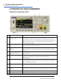
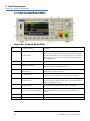
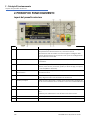
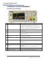
Front Panel Layout
Ref.
Short Description
Function
1
Power Switch
Switches instrument on or off. Safety Note: To fully disconnect from
the AC supply, unplug the mains cord from the back of the
instrument or switch off at the AC supply outlet; make sure that the
means of disconnection is readily accessible.
2
Soft-keys
Performs the function shown on the LCD soft-key label above.
3
Waveform Keys
Selects the main waveform type (carrier waveform) as active. (Sine,
Square, Ramp, Pulse, Noise/PBRS or Arb.)
4
Waveform Modification
Menus
Opens menus for setting parameters for Modulation, Sweep and
Burst
5
Other Menus
Selects menus for internal and external file storage, instrument
utilities, and trigger conditions.
6
Main Sockets
Main output sockets. Channel 2 can also be configured to output
Channel 1 sync from its MAIN OUT 2 socket.
7
Output Keys
Switch the selected MAIN OUT on or off.
8
Cursor Keys and Spin Wheel
Used to change numeric parameter values digit by digit.
Used to select items within some menus.
9
Numeric Keypad
Used to enter numeric parameter values directly.
10
USB Flash Drive
USB Host connector for USB Flash drive storage.

3 - Operational Principles
Rear Panel Layout
7 TGF4000 Series Quick Start Guide
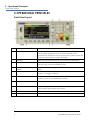
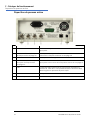
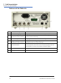
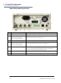
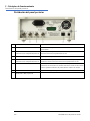
Rear Panel Layout
Ref.
Short Description
Function
1
Modulation Input
Input for external modulation of main waveforms.
2
Reference In / AC coupled
frequency counter
Input for external 10MHz reference clock and AC coupled external
frequency measurement.
3
Reference Out
Output for internal 10MHz reference clock.
4
Trigger Input / DC coupled
frequency counter
Input for external triggering of main waveforms and DC coupled
external frequency measurement
5
LAN connection
Designed to meet LXI Core 2011.Remote control is possible using
the TCP/IP Socket protocol.
6
USB connection
Accepts a standard USB cable.
7
GPIB connection (optional)
IEEE-488 The default GPIB address is 5.

3 - Operational Principles
Screen Layout
8 TGF4000 Series Quick Start Guide
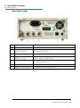
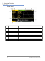
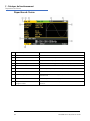
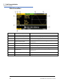
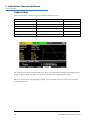
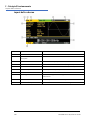
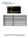
Screen Layout
Ref.
Short Description
Function
1
Channel Indicator
Shows currently selected channel
2
Main Waveform type
Shows current carrier waveform
3
Output State
Shows main output On or Off
4
External Clock Indicator
Shows status of external clock (if applied)
5
LAN Status Indicator
Shows status of LAN (Ethernet) connection.
6
Parameters Box
Shows main parameters for waveform.
7
Menu Description
Shows the currently selected editing menu.
8
Graph Box
Shows a graphical representation of the selected waveform.
9
Edit Box
Shows the current parameter that can be edited
10
Soft-key Labels
Shows the current functions for the six keys below.

4 - Getting Started
Initial Conditions
9 TGF4000 Series Quick Start Guide
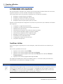
4. GETTING STARTED
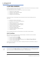
In order to familiarise the user with some of the basic functionalities of the instrument, a number
of set-up examples are shown in this guide.
It is recommended that all users should carry out the first four examples:
• Setting-up a Sine Wave Signal
• S
etting-up a Square Wave Clock Signal
• S
etting-up a Pulse Waveform
• S
etting-up more Output Options
A number of further set-up examples are provided that assume some familiarity with the
instrument:
• Setting-up an arbitrary wave signal
• Setting-up an AM modulated Sine Waveform
• P
RBS (TGF4162 & TGF4242)
• Frequency Modulation of a Sine Waveform
• Pulse Width Modulated Waveform (PWM)
• Ampl
itude shift keying (ASK)
• F
requency Sweep of a Sine Wave
• G
enerating a Triggered Burst
• C
oupling the Frequency of Both Channels
• F
requency counter
F
or more detailed information on all functionality - see the full Instruction Manual.
Initial Conditions
Before setting up the instrument for any of the examples, it should be returned to default
conditions. To do this follow these steps:
• Press the hard key marked Utility
• Press the soft-key labelled System
• Press the soft-key labelled Default (display will show Restore Factory Default?)
• Press the soft-key labelled Yes
This sets the main waveform to Sine (10kHz, 1V pk-pk) and cancels any modulations, sweep, or
burst triggering or gating.
NOTE
The instrument can be set to remember its latest settings on power-off and restore them at power-
on. This is set from the Utility > System menu and the PwrOn soft-key. This setting will be lost
when the instrument is restored to default conditions as described above.

5 - Basic Set-up Examples
Setting-up a Sine Wave Signal
10 TGF4000 Series Quick Start Guide
5. BASIC SET-UP EXAMPLES
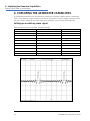
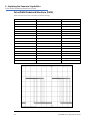
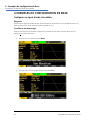
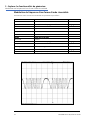
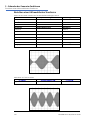
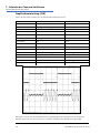
Setting-up a Sine Wave Signal
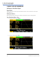
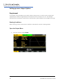
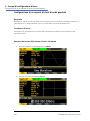
Requirement
Output a continuous sine wave signal with 40MHz frequency and an amplitude of 6 volts pk-pk
from MAIN OUT 1.
Starting Conditions
Before starting, reset the instrument to defaults as described in section 4 Getting Started
Open Waveform Menu - Sine
• Press the hard key marked Waves
• Press the soft key labelled Sine

5 - Basic Set-up Examples
Setting-up a Sine Wave Signal
11 TGF4000 Series Quick Start Guide
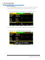
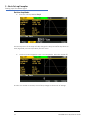
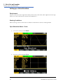
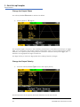
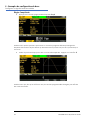
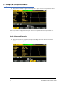
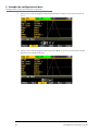
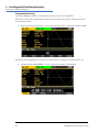
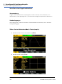
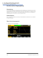
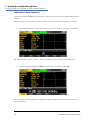
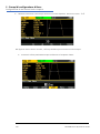
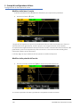
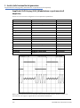
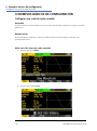
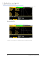
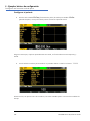
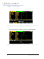
Set the Frequency
The soft key labelled Freq will be highlighted - the current frequency appears in the edit box.
Pressing this soft-key repeatedly changes its function between Frequency and Period.
• Use the numeric keypad to enter a new frequency. Press the numbers 4 0
As soon as a number is entered, the soft-keys change to show units of frequency.
• Press the soft-key labelled MHz to confirm a frequency of 40MHz.

5 - Basic Set-up Examples
Setting-up a Sine Wave Signal
12 TGF4000 Series Quick Start Guide
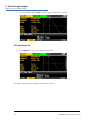
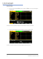
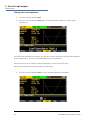
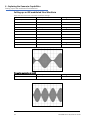
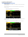
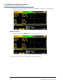
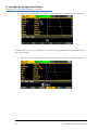
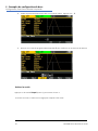
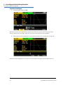
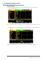
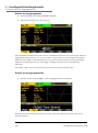
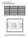
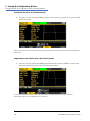
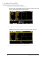
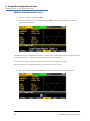
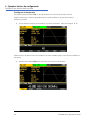
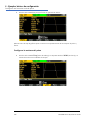
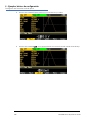
Set the Amplitude
• Press the soft key labelled Ampl
Successive presses of the Ampl soft-key changes the Ampl and Offset key labels to
HiLvl (high level) and LoLvl (low level) and vice versa.
• Use the numeric keypad to enter a new amplitude. Press the number 6
As soon as a number is entered, the soft-keys change to show units of voltage.

5 - Basic Set-up Examples
Setting-up a Sine Wave Signal
13 TGF4000 Series Quick Start Guide
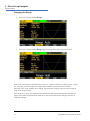
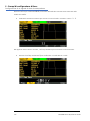
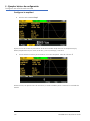
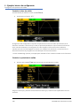
• Press the soft-key labelled Vpp to confirm a pk-pk amplitude of 6.0 volts.
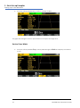
Turn the Output On
• Press Output 1 key to turn the channel 1 output On.
The Output 1 key illuminates orange to indicate the on state.

5 - Basic Set-up Examples
Setting-up a Square Wave Clock Signal
14 TGF4000 Series Quick Start Guide
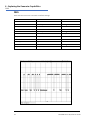
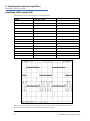
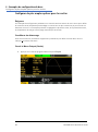
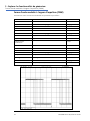
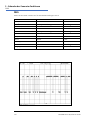
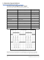
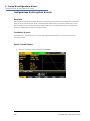
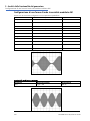
Setting-up a Square Wave Clock Signal
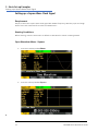
Requirement
Output a continuous square wave clock signal with 20MHz frequency, 50% duty cycle and a high
level of 3.3V and a low level of 0.0 volts from MAIN OUT 1.
Starting Conditions
Before starting, reset the instrument to defaults as described in section 4 Getting Started
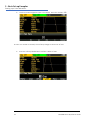
Open Waveform Menu - Square
• Press the hard key marked Waves
• Press the soft-key labelled Square.
+

5 - Basic Set-up Examples
Setting-up a Square Wave Clock Signal
15 TGF4000 Series Quick Start Guide
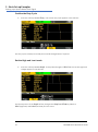
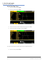
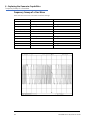
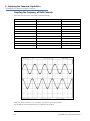
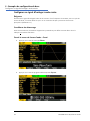
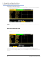
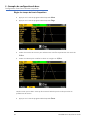
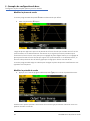
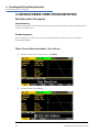
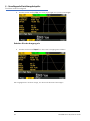
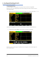
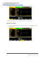
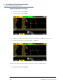
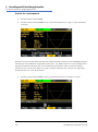
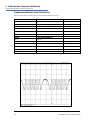
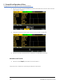
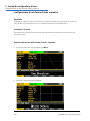
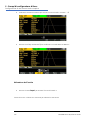
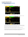
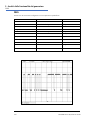
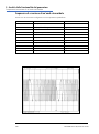
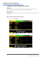
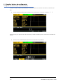
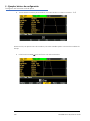
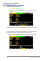
Set the Frequency
The soft key labelled Freq will be highlighted - the current frequency appears in the edit box.
Pressing this soft-key repeatedly changes its function between Frequency and Period.
• Use the numeric keypad to enter a new frequency. Press the numbers 2 0
As soon as a number is entered, the soft-keys change to show units of frequency.
• Press the soft-key labelled MHz to confirm a frequency of 20MHz.
The graph box changes to show the rise time on the edges which is now significant.

5 - Basic Set-up Examples
Setting-up a Square Wave Clock Signal
16 TGF4000 Series Quick Start Guide
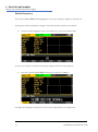
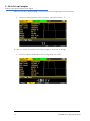
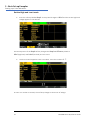
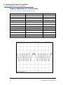
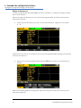
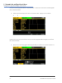
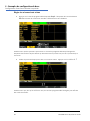
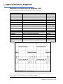
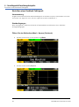
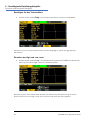
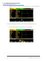
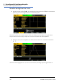
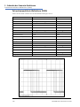
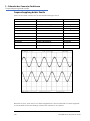
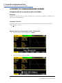
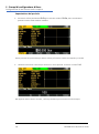
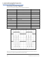
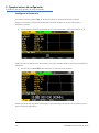
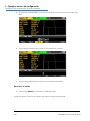
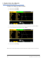
Confirm the Duty Cycle
• Press the soft-key labelled Duty - the current duty cycle appears in the edit box.
The duty cycle is already set at 50%, but could be changed here if required.
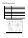
Set the High and Low Levels
• Press the soft-key labelled Ampl - the key label changes to HiLvl and the current high level
voltage appears in the edit box.
Successive presses of the Ampl soft-key changes the Ampl and Offset key labels to
HiLvl (high level) and LoLvl (low level) and vice versa.

5 - Basic Set-up Examples
Setting-up a Square Wave Clock Signal
17 TGF4000 Series Quick Start Guide
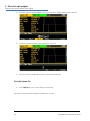
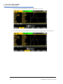
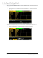
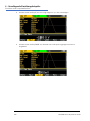
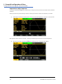
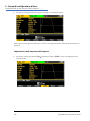
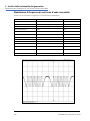
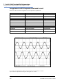
When the soft-key is labelled HiLvl - the current high level voltage appears in the edit box.
• Use the numeric keypad to enter a new level. Press the numbers 3 . 3
As soon as a number is entered, the soft-keys change to show units of voltage.
• Press the soft-key labelled V to confirm a high level of 3.3 volts.

5 - Basic Set-up Examples
Setting-up a Square Wave Clock Signal
18 TGF4000 Series Quick Start Guide
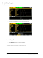
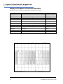
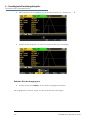
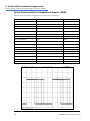
• Press the soft-key labelled LoLvl - the current low level voltage appears in the edit box.
• Use the numeric keypad to enter a new level. Press 0
• Press the soft-key labelled V to confirm a low level of 0.0 volts.
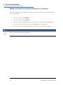
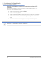
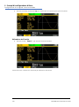
Turn the Output On
• Press Output 1 key to turn the channel 1 output On.
The Output 1 key illuminates orange to indicate the on state

5 - Basic Set-up Examples
Setting-up a Square Wave Clock Signal
19 TGF4000 Series Quick Start Guide
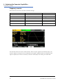
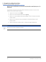
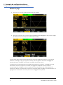
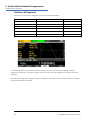
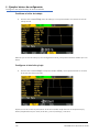
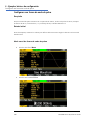
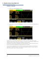
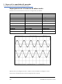
Making live changes to any numeric parameter (e.g. Frequency)
Numeric parameters can be changed by using the cursor keys and spin wheel as an alternative to
the numeric keypad.
• Press the hard key marked Waves
• Press the soft-key labelled Square.
• Press the soft-key labelled Freq – the current frequency value of 20.0MHz is displayed
• Press the Cursor hard keys to move the edit highlight to the second digit.
• Use the spin wheel to change the value – the frequency is changed immediately.
NOTE
Press to activate/ deactivate the spin wheel.
Seite laden ...
Seite laden ...
Seite laden ...
Seite laden ...
Seite laden ...
Seite laden ...
Seite laden ...
Seite laden ...
Seite laden ...
Seite laden ...
Seite laden ...
Seite laden ...
Seite laden ...
Seite laden ...
Seite laden ...
Seite laden ...
Seite laden ...
Seite laden ...
Seite laden ...
Seite laden ...
Seite laden ...
Seite laden ...
Seite laden ...
Seite laden ...
Seite laden ...
Seite laden ...
Seite laden ...
Seite laden ...
Seite laden ...
Seite laden ...
Seite laden ...
Seite laden ...
Seite laden ...
Seite laden ...
Seite laden ...
Seite laden ...
Seite laden ...
Seite laden ...
Seite laden ...
Seite laden ...
Seite laden ...
Seite laden ...
Seite laden ...
Seite laden ...
Seite laden ...
Seite laden ...
Seite laden ...
Seite laden ...
Seite laden ...
Seite laden ...
Seite laden ...
Seite laden ...
Seite laden ...
Seite laden ...
Seite laden ...
Seite laden ...
Seite laden ...
Seite laden ...
Seite laden ...
Seite laden ...
Seite laden ...
Seite laden ...
Seite laden ...
Seite laden ...
Seite laden ...
Seite laden ...
Seite laden ...
Seite laden ...
Seite laden ...
Seite laden ...
Seite laden ...
Seite laden ...
Seite laden ...
Seite laden ...
Seite laden ...
Seite laden ...
Seite laden ...
Seite laden ...
Seite laden ...
Seite laden ...
Seite laden ...
Seite laden ...
Seite laden ...
Seite laden ...
Seite laden ...
Seite laden ...
Seite laden ...
Seite laden ...
Seite laden ...
Seite laden ...
Seite laden ...
Seite laden ...
Seite laden ...
Seite laden ...
Seite laden ...
Seite laden ...
Seite laden ...
Seite laden ...
Seite laden ...
Seite laden ...
Seite laden ...
Seite laden ...
Seite laden ...
Seite laden ...
Seite laden ...
Seite laden ...
Seite laden ...
Seite laden ...
Seite laden ...
Seite laden ...
Seite laden ...
Seite laden ...
Seite laden ...
Seite laden ...
Seite laden ...
Seite laden ...
Seite laden ...
Seite laden ...
Seite laden ...
Seite laden ...
Seite laden ...
Seite laden ...
Seite laden ...
Seite laden ...
Seite laden ...
Seite laden ...
Seite laden ...
Seite laden ...
Seite laden ...
Seite laden ...
Seite laden ...
Seite laden ...
Seite laden ...
Seite laden ...
Seite laden ...
Seite laden ...
Seite laden ...
Seite laden ...
Seite laden ...
Seite laden ...
Seite laden ...
Seite laden ...
Seite laden ...
Seite laden ...
Seite laden ...
Seite laden ...
Seite laden ...
Seite laden ...
Seite laden ...
Seite laden ...
Seite laden ...
Seite laden ...
Seite laden ...
Seite laden ...
Seite laden ...
Seite laden ...
Seite laden ...
Seite laden ...
Seite laden ...
Seite laden ...
Seite laden ...
Seite laden ...
Seite laden ...
Seite laden ...
Seite laden ...
Seite laden ...
Seite laden ...
Seite laden ...
Seite laden ...
Seite laden ...
Seite laden ...
Seite laden ...
Seite laden ...
Seite laden ...
Seite laden ...
Seite laden ...
Seite laden ...
Seite laden ...
Seite laden ...
Seite laden ...
Seite laden ...
Seite laden ...
Seite laden ...
Seite laden ...
Seite laden ...
Seite laden ...
Seite laden ...
Seite laden ...
Seite laden ...
Seite laden ...
Seite laden ...
-
 1
1
-
 2
2
-
 3
3
-
 4
4
-
 5
5
-
 6
6
-
 7
7
-
 8
8
-
 9
9
-
 10
10
-
 11
11
-
 12
12
-
 13
13
-
 14
14
-
 15
15
-
 16
16
-
 17
17
-
 18
18
-
 19
19
-
 20
20
-
 21
21
-
 22
22
-
 23
23
-
 24
24
-
 25
25
-
 26
26
-
 27
27
-
 28
28
-
 29
29
-
 30
30
-
 31
31
-
 32
32
-
 33
33
-
 34
34
-
 35
35
-
 36
36
-
 37
37
-
 38
38
-
 39
39
-
 40
40
-
 41
41
-
 42
42
-
 43
43
-
 44
44
-
 45
45
-
 46
46
-
 47
47
-
 48
48
-
 49
49
-
 50
50
-
 51
51
-
 52
52
-
 53
53
-
 54
54
-
 55
55
-
 56
56
-
 57
57
-
 58
58
-
 59
59
-
 60
60
-
 61
61
-
 62
62
-
 63
63
-
 64
64
-
 65
65
-
 66
66
-
 67
67
-
 68
68
-
 69
69
-
 70
70
-
 71
71
-
 72
72
-
 73
73
-
 74
74
-
 75
75
-
 76
76
-
 77
77
-
 78
78
-
 79
79
-
 80
80
-
 81
81
-
 82
82
-
 83
83
-
 84
84
-
 85
85
-
 86
86
-
 87
87
-
 88
88
-
 89
89
-
 90
90
-
 91
91
-
 92
92
-
 93
93
-
 94
94
-
 95
95
-
 96
96
-
 97
97
-
 98
98
-
 99
99
-
 100
100
-
 101
101
-
 102
102
-
 103
103
-
 104
104
-
 105
105
-
 106
106
-
 107
107
-
 108
108
-
 109
109
-
 110
110
-
 111
111
-
 112
112
-
 113
113
-
 114
114
-
 115
115
-
 116
116
-
 117
117
-
 118
118
-
 119
119
-
 120
120
-
 121
121
-
 122
122
-
 123
123
-
 124
124
-
 125
125
-
 126
126
-
 127
127
-
 128
128
-
 129
129
-
 130
130
-
 131
131
-
 132
132
-
 133
133
-
 134
134
-
 135
135
-
 136
136
-
 137
137
-
 138
138
-
 139
139
-
 140
140
-
 141
141
-
 142
142
-
 143
143
-
 144
144
-
 145
145
-
 146
146
-
 147
147
-
 148
148
-
 149
149
-
 150
150
-
 151
151
-
 152
152
-
 153
153
-
 154
154
-
 155
155
-
 156
156
-
 157
157
-
 158
158
-
 159
159
-
 160
160
-
 161
161
-
 162
162
-
 163
163
-
 164
164
-
 165
165
-
 166
166
-
 167
167
-
 168
168
-
 169
169
-
 170
170
-
 171
171
-
 172
172
-
 173
173
-
 174
174
-
 175
175
-
 176
176
-
 177
177
-
 178
178
-
 179
179
-
 180
180
-
 181
181
-
 182
182
-
 183
183
-
 184
184
-
 185
185
-
 186
186
-
 187
187
-
 188
188
-
 189
189
-
 190
190
-
 191
191
-
 192
192
-
 193
193
-
 194
194
-
 195
195
-
 196
196
-
 197
197
-
 198
198
-
 199
199
-
 200
200
-
 201
201
-
 202
202
-
 203
203
-
 204
204
-
 205
205
-
 206
206
-
 207
207
-
 208
208
-
 209
209
-
 210
210
-
 211
211


Aim-TTI TGF4042 Schnellstartanleitung
- Typ
- Schnellstartanleitung
- Dieses Handbuch ist auch geeignet für
in anderen Sprachen
- English: Aim-TTI TGF4042 Quick start guide
- français: Aim-TTI TGF4042 Guide de démarrage rapide
- español: Aim-TTI TGF4042 Guía de inicio rápido
- italiano: Aim-TTI TGF4042 Guida Rapida
Sonstige Unterlagen
-
Yamaha YRM-502 Bedienungsanleitung
-
Wavetek 2C/3C Bedienungsanleitung
-
-
-
-
-
-
Yamaha MODX7 Benutzerhandbuch
-
-
Amprobe FG2C-UA & FG3C-UA Function Generators Benutzerhandbuch