1
FRANCAIS
ENGLISH
DEUTSCH
ITALIANO
ESPANOL
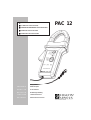
PAC 12
■■
■■
■PINCE POUR OSCILLOSCOPE
■■
■■
■CLAMP FOR OSCILLOSCOPE
■■
■■
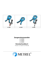
■ZANGENSTROMWANDLER FÜR OSZILLOSKOP
■■
■■
■PINZA PER OSCILLOSCOPIO
■■
■■
■PINZA PARA OSCILOSCOPIOS
Mode d'Emploi
User's Manual
Bedienungsanleitung
Libretto d'Istruzioni
Manual de Instrucciones

2
Vous venez d’acquérir une pince pour oscilloscope et nous vous remercions de votre
confiance.
Pour obtenir le meilleur service de votre appareil :
■lisez attentivement ce mode d’emploi
■respectez les précautions d’emploi
Significations du symbole
Attention ! Consulter le mode d’emploi avant d’utiliser l’appareil.
Dans le présent mode d’emploi, les instructions précédées de ce symbole, si elles ne sont
pas bien respectées ou réalisées, peuvent occasionner un accident corporel ou endomma-
ger l’appareil et les installations.
PRÉCAUTIONS D’EMPLOI
■N’utiliser la pince qu’en intérieur.
■Ne pas exposer la pince à des chutes d’eau.
■Ne pas utiliser la pince sur des conducteurs non isolés portés à un potentiel supérieur
à 600 V par rapport à la terre .
■Pour les mesures en courant continu, s’assurer du zéro de la sortie. Le régler si néces-
saire (voir «procédure d’emploi»).
■Lors de la mesure, s’assurer que le conducteur est bien dans l’alignement des repères
de mâchoires et que la fermeture de la pince est correcte.
■Votre pince est livrée avec un jeu d'étiquettes adhésives. Choisissez l'étiquette de langue
adequate et collez-la au dos du boîtier.
GARANTIE
Notre garantie s’exerce, sauf stipulation expresse, pendant douze mois après la date de
mise à disposition du matériel (extrait de nos Conditions Générales de Vente, communi-
quées sur demande).
POUR COMMANDER
Réf.
Pince PAC 12 CVH OSCILLO......................................................................................................... P01.1200.72
Livrée avec une pile alcaline 9 V, un jeu d’étiquettes cinq langues
à coller sur l’appareil et un mode d’emploi.
Rechange :
- Pile 9 V alcaline (6LF22) ................................................................................................................. P01.1006.20

3
English
........................................................................................................................................................................
10
Deutsch
.....................................................................................................................................................................
18
Italiano
........................................................................................................................................................................
26
Español
......................................................................................................................................................................
34
SOMMAIRE
page
1 Présentation ............................................................................................................................................................. 3
2 Description ................................................................................................................................................................ 4
3 Procédure d’emploi ............................................................................................................................................ 4
3.1 Mise en marche ............................................................................................................................... 4
3.2 Réglage du zéro DC ..................................................................................................................... 4
3.3 Mesure ................................................................................................................................................... 4
3.4 Indication de surcharge .............................................................................................................. 4
3.5 Arrêt automatique ........................................................................................................................... 5
4 Caractéristiques ................................................................................................................................................ 5
4.1 Conditions de référence ........................................................................................................... 5
4.2 Conditions d’utilisation ............................................................................................................... 5
4.3 Caractéristiques métrologiques ........................................................................................... 6
- Calibre 40 A (10 mV/A) .......................................................................................................... 6
- Calibre 400 A (1 mV/A) .......................................................................................................... 7
- Paramètres d’influences ....................................................................................................... 7
4.4 Caractéristiques mécaniques ............................................................................................... 7
4.5 Caractéristiques électriques .................................................................................................. 8
- Limite de fonctionnement ..................................................................................................... 8
- Chocs électriques ...................................................................................................................... 8
4.6 Compatibilité électromagnétique ........................................................................................ 8
5 Maintenance ........................................................................................................................................................... 9
5.1 Remplacement de la pile ......................................................................................................... 9
5.2 Nettoyage ........................................................................................................................................... 9
5.3 Vérification métrologique ......................................................................................................... 9
5.4 Réparation .......................................................................................................................................... 9
6 Annexe ........................................................................................................................................................................ 42
1/ PRESENTATION
La pince ampèremétrique mesure des courants continus ou alternatifs, sans ouvrir le circuit sur
lequel ils circulent. Elle s’utilise en accessoire d'oscilloscope.
Cette pince mesure les courants continus jusqu’à 600 A et les courants alternatifs jusqu’à
400 A efficace (600 crête). Elle restitue la forme et l’amplitude du courant mesuré sous l’aspect
d’une tension image du courant primaire.
La pince dispose de deux calibres 40 A (sensibilité 10 mV/A) et 400 A (sensibilité 1 mV/A),
d’un bouton poussoir de remise à zéro, d’un arrêt automatique pour économiser la pile
d’alimentation et de deux témoins, l’un de défaut (dépassement de calibre / remise à zéro
incorrecte), l’autre d’alimentation.

4
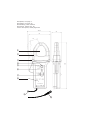
2/ DESCRIPTION
Voir schéma descriptif situé en fin de mode d’emploi.
➀Passage du conducteur
➁Mâchoires
➂Garde antiglissement de protection
➃Bouton de zéro DC automatique
➄Témoin rouge de défauts (dépassement de gamme / réglage du zéro incorrect)
➅Témoin vert d’alimentation correcte
➆Commutateur à glissière à trois positions
(arrêt / sélection de calibres 1 mV/A ou 10 mV/A)
➇Parties préhensibles
➈Cordon solidaire 1,5 m
➉Fiche BNC
3/ PROCEDURE D’EMPLOI
3.1/ MISE EN MARCHE
Mettre le commutateur à glissière ➆ sur la position adéquate calibre 40 A (sensibilité 10 mV/A)
ou calibre 400 A (sensibilité 1 mV/A). Le fonctionnement correct est signalé par un voyant de
couleur verte ⑥ indiquant le bon état de la pile.
Après environ dix minutes de fonctionnement de la pince sans manipulation des organes de
commande, l’alimentation se coupe automatiquement (voir plus loin «arrêt automatique»).
Si ce témoin vert ne s’allume pas à la mise en marche, ou vient à s’éteindre avant dix minutes
de fonctionnement, il est alors nécessaire de procéder au remplacement de la pile (voir
chapitre MAINTENANCE).
3.2/ REGLAGE DU ZERO
Assurez-vous que les mâchoires de la pince sont bien fermées et qu’elles n’enserrent aucun
conducteur. Reliez la pince à votre appareil de mesure. Appuyez sur le bouton de zéro
automatique ➃. Le témoin rouge ➄ s’allume pendant environ trois secondes pour indiquer que
l’appareil est en calibration de zéro. Si le zéro ne peut être obtenu, ce témoin reste allumé pour
signaler le défaut.
3.3/ MESURE
Après avoir mis en marche la pince, l’avoir reliée à votre oscilloscope correctement réglé et
avoir effectué le zéro automatique (voir les deux paragraphes ci-dessus), enserrez le
conducteur à mesurer entre les mâchoires de la pince ➀.
En mesure de courant continu, s’assurer que la flèche figurant sur le bord extérieur
des mâchoires ➁ correspond au sens du courant circulant dans le conducteur
(source ⇒ récepteur).
3.4/ INDICATION DE SURCHARGE
La détection de dépassement de calibre de la pince est signalée par le témoin de couleur rouge
➄. Ce témoin clignote pour un courant crête supérieur à 60 A sur le calibre 40 A
(10 mV/A) ou 600 A sur le calibre 400 A (1 mV/A).

5
3.5/ ARRET AUTOMATIQUE
La pince est équipée d’un arrêt automatique qui survient après une période, sans manipulation
des organes de commande, d'environ 10 minutes.
Lorsque la pince est mise à l’arrêt par cette fonction automatique, il faut repasser par la position
OFF du commutateur ➆ pour pouvoir la remettre en marche.
Cette fonction peut être inhibée à la mise en marche. Il suffit d’appuyer sur le bouton de zéro
automatique ➃ en même temps que l’on actionne le commutateur ➆ de la position OFF à la
position 1 mV/A ou 10 mV/A. Le clignotement du témoin vert ⑥, tant que l’on maintient la
pression sur le bouton de remise à zéro, signale que la fonction arrêt automatique est bien
inhibée.
4/ CARACTERISTIQUES
4.1/ CONDITIONS DE RÉFERENCE
- Température : 18...28°C
- Taux d’humidité : 20...75% HR
- Tension de pile : 9 V ± 0,1 V
- Position du conducteur : centré sur les repères de la pince
- Champ magnétique : champ terrestre continu
- Absence de champ magnétique alternatif externe
- Absence de champ électrique
- Mesure pour un courant continu ou un courant alternatif sinusoïdal ≤ 65 Hz
- Impédance de l’appareil de mesure : ≥ 1 MΩ et ≤ 100 pF
4.2/ CONDITIONS D’UTILISATION
L’appareil doit être utilisé dans les conditions suivantes pour satisfaire à la sécurité de
l’utilisateur et aux performances métrologiques :
- Utilisation en intérieur
- Altitude de fonctionnement : ≤ 2000 m
- Altitude de transport : ≤ 12 000 m
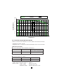
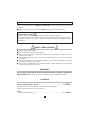
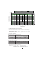
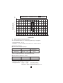
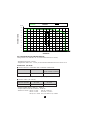
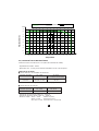
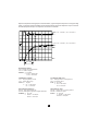
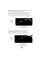
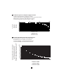
- Conditions d'environnement : voir graphe ci-dessous
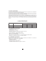
Calibres rapport entrée/sortie étendue de mesure
AC eff. crête maxi DC
40 A 10 mV/A 0,2...40 A 0,2...60 A 0,4...60 A
400 A 1 mV/A 0,5...400 A 0,5...600 A 0,5...600 A

6
0
10
20
30
40
50
60
70
80
90
-50-40-30-20-100 102030405060708090
Stockage Utilisation Réference
RéférenceStockage Utilisation
▼
°C
▼
% HR
Température
Humidité relative
4.3/ CARACTERISTIQUES METROLOGIQUES
Toutes les erreurs sont indiquées en % de Vs (valeur de la tension de sortie).
- Impédance de sortie : 100 Ω
- Réglage du zéro : ± 10 A par incrément automatique de 25 à 40 mA environ
Calibre 40 A (10 mV/A)
■Erreur intrinsèque dans le domaine de référence
Courbes d’erreur relative typique : voir en annexe, page 42.
■Erreur de phase (45...65 Hz)
Courant primaire 0,5...40 A 40...60 A
(en continu uniquement)
Précision ≤ 1,5% + 5 mV ≤ 1,5%
Courant primaire 10...20 A 20...40 A
Déphasage ≤ 3° ≤ 2,2°
- Temps de montée de 10 à 90% Vs : ≤ 100 µs
- Temps de descente de 90 à 10% Vs : ≤ 100 µs
- Bruit en sortie : de DC...1 kHz ≤ 8 mV ou 0,8 Acc
de DC...5 kHz ≤ 12 mV ou 1,2 Acc
de 0,1 Hz...5 kHz ≤ 2,0 mV rms ou 0,2 A rms

7
Calibre 400 A (1 mV/A)
■Erreur intrinsèque dans le domaine de référence
Courant primaire 0,5...100 A 100...400 A 400...600 A
(en continu
uniquement)
Précision ≤ 1,5% + 1 mV ≤ 2% ≤ 2,5%
Courbes d’erreur relative typique : voir en annexe, page 45.
■Erreur de phase (45...65 Hz)
Courant primaire 10...300 A 300...400 A
Déphasage ≤ 2,2° ≤ 1,5°
Courbe de déphasage typique en fonction d’un courant primaire alternatif 50 Hz : voir page 46.
- Temps de montée de 10 à 90% Vs : ≤ 70 µs
- Temps de descente de 90 à 10% Vs : ≤ 70 µs
- Bruit en sortie : de DC à 1 kHz ≤ 1 mV ou 1 A crête - crête
de DC à 5 kHz ≤ 1,5 mV ou 1,5 A crête - crête
de 1 Hz à 5 kHz ≤ 500 µV rms ou 0,5 A rms
Paramètres d’influences
■Influence maxi de la fréquence sur la mesure (à ajouter à l’erreur dans le domaine de
référence) : de 65 à 440 Hz - 1%
de 440 à 2000 Hz - 3,5%
de 2 à 10 kHz - 3 dB
Voir courbe de réponse en fonction de la fréquence, en annexe, page 47.
■Tension pile : ≤ 0,1% par Volt
■Température : ≤ 300 ppm /°C ou 0,3% /10°C
■Humidité 10...85% HR à température ambiante : ≤ 0,5%
■Position d’un conducteur de ∅ 20 mm : de DC à 440 Hz < 0,5%
de 440 Hz à 1 kHz < 1%
de 1 kHz à 2 kHz < 3%
de 2 kHz à 5 kHz < 10%
■Conducteur adjacent parcouru par un courant alternatif 50 Hz, à 23 mm de la pince :
< 10 mA/A
■Influence d’un champ extérieur de 400 A/m (50 Hz) sur câble centré : < 1,3 A
■Réjection de mode commun : > 65 dB A/V
■Rémanence : < 10 mA/A
4.4/ CARACTERISTIQUES MECANIQUES
- Etanchéité : IP 30 suivant IEC 529
- Enserrage :un câble ∅ 30 mm (ou deux câbles ∅ 24 mm)
une barre de section 50 x 10 mm
- Dimensions pince hors tout : 224 x 97 x 44 mm
- Cordon solidaire : 1,5 m
- Masse : 440 g environ
- Hauteur de chute : suivant IEC 68-2-32
- Protection contre les chocs : 100 g suivant IEC 68-2-27
- Vibrations : suivant IEC 68-2-6

8
4.5/ CARACTERISTIQUES ELECTRIQUES
Alimentation : pile 9 V (type 6LR61, 6LF22 ou NEDA 1604)
Autonomie : environ 50h avec une pile alcaline
Limite de fonctionnement
En courant continu : 3000 A permanent
En alternatif : 1000 A permanent jusqu’à 1 kHz
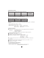
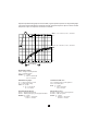
Le courant (AC) maximal admissible en surcharge à partir de 1 kHz est défini par la courbe
figurant en annexe (page 67) et selon la formule suivante :
Ip max =
Chocs électriques
Appareil à double isolation ou isolation renforcée suivant IEC 1010-2-032. Entre le primaire,
le secondaire et la partie préhensible située sous la garde, tension d’épreuve diélectrique :
7850 V DC
Tension maximum de mode commun entre le conducteur sur lequel on fait la mesure et la terre,
ou la sortie et la terre :
- 600 V pour les installations de catégorie III et degré de pollution 2
Catégorie d’installation et degré de pollution suivant IEC 664 et 664 A
4.6/ COMPATIBILITÉ ÉLECTROMAGNÉTIQUE
Susceptibilité suivant EN 50082-2 (cas le plus sévère) et EN 50082-1 :
- Décharge électrostatique suivant CEI 1000-4-2 (1995) :
tensions d'essai : 4 kV niveau 2 au contact, critère d'aptitude B.
8 kV niveau 3 dans l'air, critère d'aptitude B.
- Champs rayonnés suivant CEI 1000-4-3 (1995) :
avec influence max de 5 % de l'étendue de mesure : 3 V/m niveau 2, critère d'aptitude A.
- Transitoires rapides suivant CEI 1000-4-4 (1995) :
tension d'essai : 1 kV niveau 2, critère d'aptitude B.
- Champs magnétiques à la fréquence du réseau suivant CEI 1000-4-8 (1995) :
avec une influence max de 0,5 A : 30 A/m 50 Hz niveau 4, critère d'aptitude A.
Emissions suivant EN 50081-1 :
- Emission conduite et rayonnée suivant EN 55022 (1994) : classe B
1000
F(kHz)

9
5/ MAINTENANCE
Pour la maintenance, utilisez seulement les pièces de rechange qui ont été spéci-
fiées. Le fabricant ne pourra être tenu pour responsable de tout accident survenu
suite à une réparation effectuée en dehors de son service après-vente ou des
réparateurs agréés.
5.1/ REMPLACEMENT DE LA PILE
- Déconnecter entièrement la pince du circuit à mesurer et de votre oscilloscope.
- Dévisser la vis imperdable maintenant le couvercle de la trappe à pile.
- Remplacer la pile 9 V (type 6LF22, 6LR61 ou NEDA 1604).
- Revisser le couvercle de la trappe à pile.
5.2/ NETTOYAGE
Maintenir un parfait état de propreté au niveau de la fermeture des mâchoires.
Le nettoyage du corps de la pince est à effectuer à l’aide d’un chiffon humide imbibé d’eau
savonneuse.
Le rinçage s’effectue également avec un chiffon humide imbibé d’eau claire.
Ne jamais faire couler d’eau sur la pince.
5.3/ VERIFICATION METROLOGIQUE
Comme tous les appareils de mesure ou d’essais, une vérification périodique est
nécessaire.
Pour les vérifications et étalonnages de vos appareils, adressez-vous à nos laboratoires de
métrologie accrédités COFRAC ou aux agences Manumesure.
Renseignements et coordonnées sur demande : Tél. : 02 31 64 51 43 Fax : 02 31 64 51 09
5.4/ REPARATION
Réparation sous garantie et hors garantie.
Adressez vos appareils à l’une des agences régionales MANUMESURE, agréées CHAUVIN
ARNOUX
Renseignements et coordonnées sur demande : Tél. : 02 31 64 51 43 Fax : 02 31 64 51 09
Réparation hors de France métropolitaine.
Pour toute intervention sous garantie ou hors garantie, retournez l’appareil à votre distributeur.

10
SAFETY PRÉCAUTIONS
■Only use the clamp indoors.
■Do not expose the clamp to running water.
■Do not use the clamp on uninsulated conductors at a voltage of more than 600 V in
relation to the earth.
■For measurements on DC current, check zero output. Adjust if necessary (see “ Operating
procedure ”).
■During measurement, ensure that the conductor is in line with the markings on the jaws
and that the clamp closes correctly.
■Your clamp is supplied with a set of adhesive labels. Choose the label for your language
and stick it to the back of the case.
WARRANTY
Our guarantee is applicable for twelve months after the date on which the equipment is
made available (extract from our General Conditions of Sale, available on request).
TO ORDER
Ref.
Oscilloscope Clamp PAC 12 CVH ........................................................... P01.1200.72
Supplied with a 9 V alkaline battery, a set of labels in 5 languages
to stick to the instrument, and a User Manual.
Spare:
- 9 V alkaline battery (6LF22) ..................................................................... P01.1006.20
Thank you for purchasing a Clamp for oscilloscope. To get the best service from this
instrument:
■ read this user’s manual carefully and respect the safety precautions detailed
ENGLISH
Meaning of the symbol
Warning ! Please refer to the User’s Manual before using the instrument.
In this User’s Manual, the instructions preceded by the above symbol, should they not be
carried out as shown, can result in a physical accident or damage the instrument and the
installations.

11
SUMMARY
page
1 Presentation ........................................................................................................................................................... 11
2 Description .............................................................................................................................................................. 12
3 Operating procedure ....................................................................................................................................... 12
3.1 Switching on ....................................................................................................................................... 12
3.2 DC zero adjustment ...................................................................................................................... 12
3.3 Measurement ..................................................................................................................................... 12
3.4 Overload indication ........................................................................................................................ 13
3.5 Auto off ................................................................................................................................................... 13
4 Specifications ....................................................................................................................................................... 13
4.1 Reference conditions .................................................................................................................... 13
4.2 Operating conditions ..................................................................................................................... 13
4.3 Metrological specifications ....................................................................................................... 14
- 40 A range (10 mV/A) ............................................................................................................... 14
- 400 A range (1 mV/A) ............................................................................................................... 15
- distortion parameters ................................................................................................................ 15
4.4 Mechanical specifications ......................................................................................................... 15
4.5 Electrical specifications .............................................................................................................. 16
- Operating limits ............................................................................................................................. 16
- Electric shocks ............................................................................................................................... 16
4.6 Electromagnetic compatibility ................................................................................................. 16
5 Maintenance ........................................................................................................................................................... 17
5.1 Replacing the battery ................................................................................................................... 17
5.2 Cleaning ................................................................................................................................................ 17
5.3 Calibration ............................................................................................................................................ 17
5.4 Repair ..................................................................................................................................................... 17
6 Appendix ................................................................................................................................................................... 42
1/ PRESENTATION
The oscilloscope clamp measures DC or AC currents, without opening the circuit they
are flowing in. The current clamp is used as an accessory for multimeters, recorders, etc.
This clamp measures DC currents up to 600 A and AC currents up to 400 A rms (600 A peak).
It outputs the form and amplitude of the current measured as a voltage image of the primary
current.
The clamp has two ranges, 40 A (sensitivity 10 mV/A) and 400 A (sensitivity 1 mV/A), a
zero adjust push button, auto off feature to economise the battery power supply and two
light indicators, one for faults (over-range / incorrect zero reset), the other for power supply.

12
2/ DESCRIPTION
See descriptive diagram at the end of the User Manual.
➀Passage of the conductor
➁Jaws
➂Protective non-slip guard
➃Automatic zero DC button
➄Red fault light (over range / incorrect zero adjustment)
➅Green light indicating correct power supply
➆3-position sliding switch (off / selection of 1 mV/A or 10 mV/A ranges)
➇Hand-held parts
➈Fitted lead 1.5 m
➉BNC plug
3/ OPERATING PROCEDURE
3.1/ SWITCHING ON
Set the sliding switch ➆ to the appropriate position, 40 A range (sensitivity 10 mV/A) or 400 A
range (sensitivity 1 mV/A). Correct operation is indicated by a green light ➅ indicating that
the battery is in good condition.
After approximately 10 minutes of operation of the clamp without manipulation of the
control buttons, the power supply cuts off automatically (see “ Auto off ” below).
If this green indicator does not come on when the clamp is switched on, or goes out
before it has operated for 10 minutes, it is necessary to replace the battery (see
MAINTENANCE chapter).
3.2/ DC ZERO ADJUSTMENT
Ensure that the jaws of the clamp are correctly closed and that they do not enclose any
conductor. Connect the clamp to your measurement instrument. Press the auto zero
button ➃. The red light ➄ comes on for approximately three seconds to indicate that the
instrument is on zero calibration. If zero can not be obtained, this indicator light remains
lit to indicate the fault.
3.3/ MEASUREMENT
After having switched on the clamp, connected it to the measurement instrument on the
appropriate range, and followed the auto zero procedure (see the two paragraphs above),
clamp the conductor to be measured ➀ between the jaws of the clamp.
On DC current measurement, ensure that the arrow located on the external edge of
the jaws ➁ corresponds to the direction of the current flowing in the conductor
(source ⇒ receiver).

13
3.4/ OVERLOAD INDICATION
Detection of overload of the range of the clamp is indicated by the red light ➄. This
indicator flashes for a peak current greater than 60 A on the 40 A range (10 mV/A) or
600 A on the 400 A range (1 mV/A).
3.5/ AUTO OFF
The clamp has an Auto Off feature which switches off 10 minutes after the clamp has been
switched on, without the controls being used.
When the clamp is switched off by this automatic function, the switch ➆ must first be set to the
OFF position before being switched on again.
This function can be overridden by the user when switching on. Simply press the auto zero
button ➃ at the same time as setting the switch ➆ from the OFF position to the 1 mV/A or
10 mV/A position. If the green indicator ➅ flashes whilst the zero reset button is being pressed,
this indicates that the auto off function has been inhibited.
4/ SPECIFICATIONS
Ranges input/output ratio measurement extent
AC rms peak max DC
40 A 10 mV/A 0.2...40 A 0.2...60 A 0.4...60 A
400 A 1 mV/A 0.5...400 A 0.5...600 A 0.5...600 A
4.1/ RÉFERENCE CONDITIONS
- Temperature: 18...28°C
- Humidity rate: 20...75% RH
- Battery voltage: 9 V ± 0.1 V
- Position of conductor: centred on the markings of the clamp
- Magnetic field: Earth’s DC field
- Absence of external AC magnetic field
- Absence of electric field
- Measurement for a DC current or an AC sinusoidal current ≤ 65 Hz
- Impedance of the measurement instrument : ≥ 1 MΩ and ≤ 100 pF
4.2/ OPERATING CONDITIONS
The instrument must be used in the following conditions to satisfy the safety of the user and
the metrological performance:
- Use indoors
- Working altitude: ≤ 2000 m
- Transportation altitude: ≤12 000 m
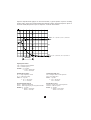
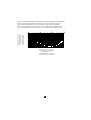
- Environmental conditions: see graph below

14
0
10
20
30
40
50
60
70
80
90
-50-40-30-20-100 102030405060708090
Stockage Utilisation Réference
▼
°C
▼
% RH Storage Use Reference
Relative humidity
Temperature
4.3/ METROLOGICAL SPECIFICATIONS
All the errors are indicated as a % of Vs (value of the output voltage)
- Output impedance: 100 Ω
- Zero adjustment: ± 10 A by automatic step from 25 to 40 mA approx.
40 A range (10 mV/A)
■Intrinsic error in the field of reference
Graphs of typical relative error: see appendix, page 42.
■Phase error (45...65 Hz)
Primary current 0.5...40 A 40...60 A
(on DC only)
Accuracy ≤ 1.5% + 5 mV ≤ 1.5%
Primary current 10...20 A 20...40 A
Phase shift ≤ 3° ≤ 2,2°
- Rise time from 10 to 90% Vs: ≤ 100 µs
- Fall time from 90 to 10% Vs: ≤ 100 µs
- Output noise : from DC...1 kHz ≤ 8 mV or 0.8 A DC
from DC...5 kHz ≤ 12 mV or 1.2 A DC
from 0.1 Hz...5 kHz ≤ 2.0 mV rms or 0.2 A rms

15
400 A range (1 mV/A)
■Intrinsic error in the reference range
Graph of typical phase shift as a function of a 50 Hz AC primary current: see appendix,
page 46.
- Rise time from 10 to 90% Vs: ≤ 70 µs
- Fall time from 90 to 10% Vs: ≤ 70 µs
- Output noise: from DC...1 kHz ≤ 1 mV or 1 A peak-peak
from DC...5 kHz ≤ 1.5 mV or 1.5 A peak-peak
from 1 kHz...5kHz ≤ 500 µV rms or 0.5 A rms
Distortion parameters
■Maximum distortion of the frequency on the measurement (to be added to the error in the
reference range): from 65 to 440 Hz -1%
from 440 to 2000 Hz -3.5%
from 2 to 10 kHz -3 dB
See graph of response as a function of the frequency, in appendix, page 47.
■Battery voltage: ≤ 0.1% /V
■Temperature: ≤ 300 ppm /°C or 0.3% /10°C
■Humidity 10...85% RH at ambient temperature: ≤ 0.5%
■Position of a conductor of ∅ 20 mm:from DC...440 Hz < 0.5%
from 440 Hz...1 kHz < 1%
from 1kHz...2 kHz < 3%
from 2kHz...5 kHz < 10%
■Adjacent conductor carrying an AC current 50 Hz, at 23 mm from the clamp: < 10 mA/A
■Distortion of an external field of 400 A/m (50 Hz) on centred cable: < 1.3 A
■Common mode rejection: > 65 dB A/V
■Residual magnetism: < 10 mA/A
4.4/ MECHANICAL SPECIFICATIONS
- Watertightness: IP 30 in accordance with IEC 529
- Clamping diameter: 1 cable ∅ 30 mm (or 2 cables ∅ 24 mm)
a busbar of cross section 50 x 10 mm
- Outside dimensions of clamp: 224 x 97 x 44 mm
- Fitted lead: 1.5 m
- Weight: 440 g approx
Primary current 0.5...100 A 100...400 A 400...600 A
(on DC only)
Accuracy ≤ 1.5% + 1 mV ≤ 2% ≤ 2.5%
Graphs of typical relative error: see appendix, page 45.
■Phase error (45...65 Hz)
Primary current 10...300 A 300...400 A
Phase shift ≤ 2,2° ≤ 1.5°

16
- Drop height: to IEC 68-2-32
- Protection from shocks: 100 g in accordance with IEC 68-2-27
- Vibrations: to IEC 68 - 2 - 6
4.5/ ELECTRICAL SPECIFICATIONS
Power supply: 9 V battery (type 6LR61, 6LF22 or NEDA 1604)
Battery life: approx 50h with an alkaline battery
Operating limits
On DC current: 3000 A permanent
On AC: 1000 A permanent up to 1 kHz
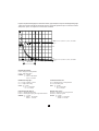
The maximum permitted current (AC) on overload from 1 kHz is defined by the curve shown
in the appendix (page 67) and in accordance with the following formula:
Ip max =
Electric shocks
Instrument with dual insulation or strengthened insulation in accordance with IEC 1010-2-032.
Between the primary, the secondary and the hand-held part located below the guard, dielectric
test voltage: 7850 V DC
Maximum common mode voltage between the conductor on which the measurement is made
and the earth, or the output and the earth:
- 600 V for installations of category III and degree of pollution 2
Installation category and degree of pollution in accordance with IEC 664 and 664A
4.6/ ÉLECTROMAGNÉTIC COMPATIBILITY
Susceptibility in accordance with EN 50082-2 (most severe case) and EN 50082-1:
Electrostatic discharge in accordance with IEC 1000-4-2 (1995):
. test voltages:4 kV level 2 on contact, aptitude criteria B
8 kV level 3 in the air, aptitude criteria B
- Radiated fields in accordance with IEC 1000-4-3 (1995):
. with max distorsion of 5% of the measurement extent: 3 V/m level 2, aptitude criteria A
- Rapid transients in accordance with IEC 1000-4-4 (1995):
. test voltage: 1 kV level 2, aptitude criteria B
- Magnetic fields at the frequency of the network to IEC 1000-4-8 (1995):
. with a max distortion of 0.5 A: 30 A/m 50 Hz level 4, aptitude criteria A
Emissions in accordance with EN 50081-1:
- Conducted and radiated emission to EN 55022 (1994): class B
1000
F (kHz)

17
5/ MAINTENANCE
For maintenance, use only specified spare parts. The manufacturer will not be
held responsible for any accident occurring following a repair done other than
by its After Sales Service or approved repairers.
5.1/ REPLACING THE BATTERY
- Completely disconnect the clamp from the circuit to be measured from your oscilloscope.
- Unscrew the tool release screw holding the cover of the battery compartment.
- Replace the 9 V battery (type 6LF22, 6LR61 or NEDA 1604).
- Replace the cover of the battery compartment.
5.2/ CLEANING
Keep the jaw faces and mechanism perfectly clean.
The body of the clamp should be cleaned with a cloth moistened with soapy water.
Rinse with a cloth moistened with clean water.
Never expose the clamp to running water.
5.3/ CALIBRATION
It is essential that all measuring instruments are regularly calibrated.
For checking and calibration of your instrument, please contact our accredited laboratories (list
on request) or the Chauvin Arnoux subsidiary or Agent in your country.
5.4/ MAINTENANCE
Repairs under or out of guarantee: please return the product to your distributor.

18
Wir bedanken uns bei Ihnen für den Kauf des zangenstromwandler für oszilloskop und das damit
entgegengebrachte Vertrauen. Um die besten Ergebnisse mit Ihrem Meßgerät zu erzielen, bitten
wir Sie :
■die vorliegende Bedienungsanleitung aufmerksam zu lesen
■die darin enthaltenen Sicherheitshinweise zu beachten
DEUTSCH
SICHERHEITSHINWEISE
■Verwenden Sie den Zangenstromwandler nur in Innenräumen !
■Den Stromwandler nicht mit Wasser bespritzen oder in Wasser eintauchen.
■Verwenden Sie den Zangenstromwandler niemals an nicht isolierten Leitern, die ein Potential
von mehr als 600 V gegenüber Erde aufweisen.
■Vergewissern Sie sich vor Gleichstrommessungen, daß der Zangenausgang auf Null liegt.
Nehmen Sie gegebenenfalls einen Nullabgleich der Zange vor (siehe “Bedienungshinweise”).
■Achten Sie bei Messungen darauf, daß die Lage des Leiters mit den Markierungen auf den
Zangenbacken übereinstimmt und daß die Backen richtig geschlossen sind.
■Der Zangenstromwandler wird mit einem Satz Aufklebe - Etiketten geliefert. Etikett in
entsprechender Sprache auf das Gerät aufkleben.
GARANTIE
Unsere Garantie erstreckt sich auf eine Dauer von zwölf Monaten ab dem Zeitpunkt der
Bereitstellung des Geräts (Auszug aus unseren allg. Verkaufsbedingungen. Erhältlich auf
Anfrage).
BESTELLANGABEN
Best. Nr.
ZANGENSTROMWANDLER PAC 12 CVH für Oszilloskop.......................................................... 1200.72
Lieferung mit 9V-Alkali-Batterie, einem Satz Aufklebe-Etiketten in 5 Sprachen für
das Gerät und Bedienungsanleitung
Bedeutung des Zeichens
Achtung ! Beachten Sie vor Benutzung des Gerätes die Hinweise in der Bedienungsanleitung.
Falls die Anweisungen die in vorliegender Bedienungsanleitung nach diesem Zeichen erscheinen
nicht beachtet bzw. nicht ausgeführt werden, können körperliche Verletzungen verursacht bzw.
das Gerät und die Anlagen beschädigt werden.

19
INHALTSÜBERSICHT
Seite
1 Gerätevorstellung ............................................................................................................................................................................... 19
2 Gerätebeschreibung ........................................................................................................................................................................ 20
3 Bedienungshinweise ...................................................................................................................................................................... 20
3.1 Einschalten ........................................................................................................................................................................ 20
3.2 Nullabgleich für DC-Strommessungen ............................................................................................. 20
3.3 Strommessungen ....................................................................................................................................................... 20
3.4 Überlastanzeige ........................................................................................................................................................... 20
3.5 Automatische Abschaltung ............................................................................................................................. 21
4 Technische Daten ............................................................................................................................................................................... 21
4.1 Bezugsbedingungen ............................................................................................................................................... 21
4.2 Betriebsbedingungen ............................................................................................................................................. 21
4.3 Meßtechnische Eigenschaften ................................................................................................................... 22
- Bereich 40 A (10 mV/A) .................................................................................................................................. 22
- Bereich 400 A (1 mV/A) .................................................................................................................................. 23
- Einflußgrößen auf den Meßfehler ....................................................................................................... 23
4.4 Mechanische Eigenschaften ......................................................................................................................... 23
4.5 Elektrische Eigenschaften ............................................................................................................................... 24
- Betriebs-Grenzwerte .......................................................................................................................................... 24
- Elektrische Stöße ................................................................................................................................................. 24
4.6 Elektromagnetische Verträglichkeit ...................................................................................................... 24
5 Wartung ............................................................................................................................................................................................................25
5.1 Batteriewechsel ............................................................................................................................................................ 25
5.2 Reinigen ................................................................................................................................................................................ 25
5.3 Meßgerät -Überprüfung ...................................................................................................................................... 25
5.4 Reparaturen ..................................................................................................................................................................... 25
6 Anhang ............................................................................................................................................................................................................. 42
1/ GERÄTEVORSTELLUNG
Der Zangenstromwandler dient zur Messung von Gleich- oder Wechselströmen in Leitern
während des Betriebs und ohne diese zu unterbrechen. Der Zangenstromwandler dient als
Meßzubehör für Oszilloskope.
Der Meßumfang der Zangenstromwandler reicht bis 600 A bei Gleichströmen und bis 400 A bei
Wechselströmen (600 V Spitze). Die Zange liefert am Ausgang eine Spannung, die in Form und
Amplitude genau dem im Primärkreis gemessenen Strom entspricht.
Der Zangenstromwandler besitzt zwei umschaltbare Meßbereiche: 40 A (Empfindlichkeit 10 mV/
A) und 400 A (Empfindlichkeit 1 mV/A), eine Taste für den Nullabgleich und zwei Kontrolleuchten:
eine grüne LED für Stromversorgung und eine rote LED bei Fehlern (Überlast oder falscher
Nullabgleich). Zur Schonung der Batterie schaltet sich die Zange automatisch bei Nichtbenutzung
ab.

20
2/ GERÄTEBESCHREIBUNG
Die Zeichnung am Ende der Bedienungsanleitung :
➀Ausschnitt für Leiter
➁Zangenbacken
➂Schutzring
➃Taste für automatischen DC-Nullabgleich
➄rote Fehler-Kontrolleuchte (Überlast/falscher Nullabgleich)
➅grüne Einschalt- und Batteriekontrolleuchte
➆Schiebeschalter: AUS, Bereich 1 mV/A, Bereich 10 mV/A
➇Griff mit Zangenöffnungshebel
➈fest verbundenes Anschlußkabel, 1,5 m lang
➉BNC-Stecker
3/ BEDIENUNGSHINWEISE
3.1/ EINSCHALTEN
Wählen Sie mit dem Schiebeschalter ➆ den geeigneten Meßbereich aus : Bereich 40 A (10 mV/A)
oder 400 A (1 mV/A).
Die grüne LED ➅ leuchtet bei eingeschaltetem Gerät und korrekter Batterie Stromversorgung.
Wird der Zangenstromwandler ca. 10 Minuten lang nicht benutzt (d.h. kein Bedienungselement
betätigt) schaltet er sich automatisch aus (siehe unten unter “Automatische Abschaltung”).
Wenn die LED ➄ nicht leuchtet oder nach einigen Minuten (<10mn) Betrieb erlöscht, muß die
Batterie gewechselt werden (siehe Abschnitt WARTUNG).
3.2/ NULLABGLEICH FÜR DC-STROMMESSUNGEN
Achten Sie darauf, daß die Backen der Zange richtig geschlossen sind und kein Leiter umschlossen
wird. Schließen Sie den Zangenstromwandler an das Meßgerät an und drücken Sie auf die Taste
➃ für automatischen Nullabgleich. Die rote Kontrolleuchte ➄ leuchtet dann für ca. 3 Sekunden um
anzuzeigen, daß der Nullabgleich durchgeführt wird. Kann die “Null” nicht richtig eingestellt
werden, leuchtet die rote LED weiter, um den Fehler anzuzeigen.
3.3/ STROMMESSUNGEN
Nach Einschalten des Zangenstromwandlers, Anschluß an den Oszilloskop mit geeigneten
Meßbereich und richtigem Nullabgleich (siehe Punkte 3.1 und 3.2 oben) umschließen Sie den zu
messenden Leiter im Ausschnitt ➀ mit den Zangenbacken ➁.
Achten Sie bei Gleichstrommessungen darauf, daß der Strom in Richung des Pfeils auf den
Zangenbacken ➁ durch die Zange fließt (Stromquelle ⇒ Verbraucher).
3.4/ ÜBERLASTANZEIGE
Bei Überschreitung des Meßbereichs der Zange blinkt die rote Kontrolleuchte ➄ auf.
Dies ist der Fall bei Stromspitzen über 60 A im Bereich 40 A (10 mV/A) bzw. von mehr als 600 A
im Bereich 400 A (1 mV/A).
Seite wird geladen ...
Seite wird geladen ...
Seite wird geladen ...
Seite wird geladen ...
Seite wird geladen ...
Seite wird geladen ...
Seite wird geladen ...
Seite wird geladen ...
Seite wird geladen ...
Seite wird geladen ...
Seite wird geladen ...
Seite wird geladen ...
Seite wird geladen ...
Seite wird geladen ...
Seite wird geladen ...
Seite wird geladen ...
Seite wird geladen ...
Seite wird geladen ...
Seite wird geladen ...
Seite wird geladen ...
Seite wird geladen ...
Seite wird geladen ...
Seite wird geladen ...
Seite wird geladen ...
Seite wird geladen ...
Seite wird geladen ...
Seite wird geladen ...
Seite wird geladen ...
Seite wird geladen ...
Seite wird geladen ...
Seite wird geladen ...
Seite wird geladen ...
-
 1
1
-
 2
2
-
 3
3
-
 4
4
-
 5
5
-
 6
6
-
 7
7
-
 8
8
-
 9
9
-
 10
10
-
 11
11
-
 12
12
-
 13
13
-
 14
14
-
 15
15
-
 16
16
-
 17
17
-
 18
18
-
 19
19
-
 20
20
-
 21
21
-
 22
22
-
 23
23
-
 24
24
-
 25
25
-
 26
26
-
 27
27
-
 28
28
-
 29
29
-
 30
30
-
 31
31
-
 32
32
-
 33
33
-
 34
34
-
 35
35
-
 36
36
-
 37
37
-
 38
38
-
 39
39
-
 40
40
-
 41
41
-
 42
42
-
 43
43
-
 44
44
-
 45
45
-
 46
46
-
 47
47
-
 48
48
-
 49
49
-
 50
50
-
 51
51
-
 52
52