VEVOR EM4659 Benutzerhandbuch
- Kategorie
- Messen, Testen
- Typ
- Benutzerhandbuch

Technical Support and E-Warranty Certificate www.vevor.com/support
TRMS CLAMP MULTIMETER
USER MANUAL
MODEL:EM4659
We continue to be committed to provide you tools with competitive price.
"Save Half", "Half Price" or any other similar expressions used by us only represents an
estimate of savings you might benefit from buying certain tools with us compared to the major
top brands and doses not necessarily mean to cover all categories of tools offered by us. You
are kindly reminded to verify carefully when you are placing an order with us if you are
actually saving half in comparison with the top major brands.

- 2 -
MODEL:EM4659
Have product questions? Need technical support? Please feel free to
contact us:
CustomerService@vevor.com
NEED HELP? CONTACT US!
This is the original instruction, please read all manual instructions
carefully before operating. VEVOR reserves a clear interpretation of our
user manual. The appearance of the product shall be subject to the
product you received. Please forgive us that we won't inform you again if
there are any technology or software updates on our product.
TRMS CLAMP
MULTIMETER

- 3 -
WARRANTY
This instrument is warranted to be free from defects in material and
workmanship for a period of one year. Any instrument found defective
within one year from the delivery date and returned to the factory with
transportation charges prepaid, will be repaired,adjusted, or replaced at no
charge to the original purchaser. This warranty does not cover expandable
items such as battery. If the defect has been caused by a misuse or
abnormal operating condition, the repair will be billed at a nominal cost.
INTRODUCTION
This instrument is a 3 5/6digits true-RMS auto range digital clamp meter
designed to measure DC and AC voltage, DC and AC current, resistance,
continuity, diode,capacitance, frequency, duty cycle, and temperature.
It features inrush current measurement, VFD voltage measurement, VFD
current measurement, non-contact AC voltage detection, relative
measurement, MIN MAX mode, data hold, bar graph, backlight, low battery
indication, automatic power-off, illumination, full-range overload
protection, etc. It is easy to operate and is a useful test tool
SAFETY INFORMATION
This meter has been designed according to IEC 61010 concerning
electronic measuring instruments with a measurement category ( CAT III
1000V ) and Pollution Degree 2.

- 4 -
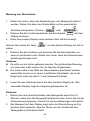
Warning
To avoid possible electric shock or personal injury, follow these
guidelines:
Do not use the meter if it is damaged. Before you use the meter,
inspect the case. Pay particular attention to the insulation surrounding
the connectors.
Inspect the test leads for damaged insulation or exposed metal. Check
the test leads for continuity. Replace damaged test leads before you
use the meter.
Do not use the meter if it operates abnormally.
Protection may be impaired. When in doubt, have the meter serviced.
Do not operate the meter where explosive gas, vapor or dust is
present.
Do not apply more than the rated voltage, as marked on the meter,
between terminals or between any terminal and earth ground.
Before use, verify the meter's operation by measuring a known
voltage.
When servicing the meter, use only specified replacement parts.
Use caution when working with voltage above 30V ac rms, 42V ac
peak, or 60V dc. Such voltages pose a shock hazard.
When using the probes, keep your fingers behind the finger guard on
the probes.
When making connections, connect the common test lead before you
connect the live test lead. When you disconnect test leads, disconnect
the live test lead first.
Remove the test leads from the meter and the clamp from any
conductor under test before you open the battery cover or the case.
Do not operate the meter with the battery cover or portions of the case
removed or loosened.
To avoid false readings, which could lead to possible electric shock or
personal injury, replace the batteries as soon as the low battery

- 5 -
indicator ( ) appears.
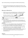
When in Relative mode or Data Hold mode or after zeroing the display
in DC current function, caution must be used because hazardous
voltage may be present.
Use the meter only as specified in this manual; otherwise the
protection provided by the meter may be impaired.
Adhere to local and national safety codes. Individual protective
equipment must be used to prevent shock and arc blast injury where
hazardous live conductors are exposed.
To avoid electric shock and personal injury, do not touch any naked
conductor with your hand or skin; and do not ground yourself while
using this meter.
Do not use the meter if the meter, a test lead or your hand is wet.
Remaining endangerment:
When an input terminal is connected to dangerous live potential, it is to
be noted that this potential can occur at all other terminals!
Do not use the VFD voltage measurement function or VFD current
measurement function to verify the presence of hazardous voltages or
currents. Voltages or currents greater than what is indicated may be
present.
CAT III - Measurement Category III is for measurements performed in
the building installation. Examples are measurements on distribution
boards, circuit breakers, wiring, including cables, bus-bars, junction
boxes,switches, socket-outlets in the fixed installation, and
equipment for industrial use and some other equipment, for example,
stationary motors with permanent connection to the fixed installation.
Do not use the meter for measurements within Measurement Category
IV.

- 6 -
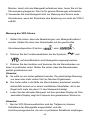
Caution
To avoid possible damage to the meter or to the equipment under test,
follow these guidelines:
Disconnect circuit power and discharge all capacitors thoroughly
before testing resistance, continuity, diode,capacitor, or temperature of
an object.
Use the proper terminals, function and range for your measurements.
Before pressing a button to change function, disconnect the test leads
and the clamp from any object under test.
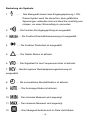
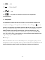
Symbols
Alternating Current
Direct Current
DC or AC
Caution, risk of danger, refer to the operating manual before use.
Caution, risk of electric shock.
Earth ( ground ) Terminal
Conforms to European Union directives
The equipment is protected throughout by double insulation or
reinforced insulation.
Application around and removal from hazardous live conductors is
permitted.

- 7 -
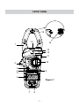
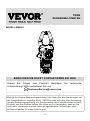
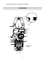
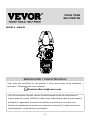
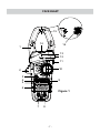
FRONT PANEL
Figure 1
1
2
3
4
5
6
9
11
12
13
16
7 8
15
14
10

- 8 -
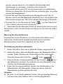
1. Jaws
Used for clamping the conductor for current measurements. The
conductor should be positioned at the center of the jaws during
measurement.
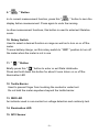
2. Trigger
Used to open and close the jaws.
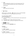
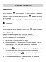
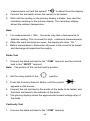
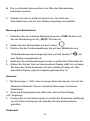
3. " " Button
With the meter on, press this " " button to turn on oroff the backlight.
The backlight will turn off automaticallyafter about 30 secs.
4. Function Selector Button
Used to switch between:
DC current, AC current, VFD current and inrush current measurement
functions.
DC voltage and AC voltage measurement functions.
Resistance, diode, continuity and capacitance test functions.
5. " " Button
Used to enter or exit the MIN MAX mode.
6. Display
35/6digits LCD.
7. " COM " Terminal
Plug-in connector for the black test lead.
8. " INPUT " Terminal
Plug-in connector for the red test lead.

- 9 -
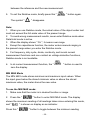
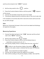
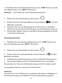
9. " " Button
In dc current measurement function, press this " " button to zero the
display before measurement. Press again to undo the zeroing.
In other measurement functions, this button is used to enter/exit Relative
mode.
10. Rotary Switch
Used to select a desired function or range as well as to turn on or off the
meter.
To save battery charge, set this rotary switch to " OFF " position to turn off
the meter when the meter is not in use.
11. " " Button
Briefly press this " " button to enter or exit Data Holdmode.
Press and hold down this button for about 2 secs toturn on or off the
illumination LED
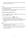
12. Tactile Barrier
Used to prevent finger from touching the conductor under test.
Do not hold the meter anywhere beyond the tactile barrier.
13. RED LED
An indicator used in non-contact ac voltage detection and continuity test.
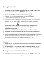
14. Illumination LED
15. NCV Sensor

- 10 -
This NCV sensor is located at the mark " " near the top of the clamp.
It is used in non-contact ac voltage detection.
16. Jaw Wear Indicator
Warning:
To avoid injury, do not use the meter if the jaw wear indicator in the jaw
opening is invisible.
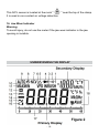
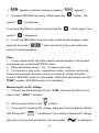
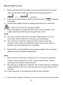
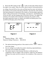
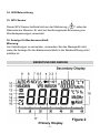
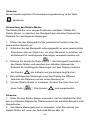
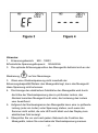
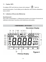
UNDERSTANDING THE DISPLAY

- 11 -
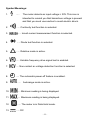
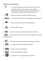
Symbol Meanings:
1. ..... The meter detects an input voltage > 30V. This icon is
intended to remind you that hazardous voltage is present
and that you must use caution to avoid electric shock.
2. ..... Continuity test function is selected.
3. ..... Inrush current measurement function is selected.
4. ..... Diode test function is selected.
5. ..... Relative mode is active.
6. ..... Variable frequency drive signal test is enabled.
7. ..... Non-contact ac voltage detection function is selected.
8. ..... The automatic power-off feature is enabled.
9. ..... Autorange mode is active.
10. ..... Minimum reading is being displayed.
11. ..... Maximum reading is being displayed.
12. ..... The meter is in Data Hold mode.
13. ..... DC

- 12 -
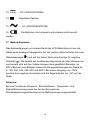
14. ..... Negative sign
15. ..... AC
16. ..... The batteries are low and must be replaced immediately.
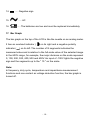
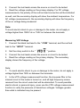
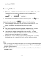
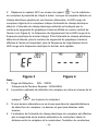
17. Bar Graph
The bar graph on the top of the LCD is like the needle on an analog meter.
It has an overload indicator ( ) on its right and a negative polarity
indicator ( ) on its left. The number of lit segments indicates the
measured value and is relative to the full-scale value of the selected range.
In the 600V range, for example, the major divisions on the scale represent
0, 100, 200, 300, 400, 500 and 600V. An input of -100V lights the negative
sign and the segments up to the " 10 " on the scale.
Note:
In frequency, duty cycle, temperature and capacitance measurement
functions and non-contact ac voltage detection function, the bar graph is
turned off.

- 13 -
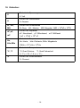
18. Units:
VUnit of voltage
V: Volt
AUnit of current
A: Ampere
Ω , kΩ ,
MΩ
Unit of resistance
Ω: Ohm; kΩ : Kilohm; MΩ: Megohm 1MΩ = 103kΩ = 106Ω
nF, µF,
mF
Unit of capacitance
nF: Nanofarad; µF: Microfarad; mF: Millifarad
1mF = 103pF = 106nF
Hz,
kHz,MHz
Unit of frequency
Hz: Hertz; kHz: Kilohertz; MHz: Megahertz
1MHz = 103kHz = 106Hz
°C, °F
Unit of temperature
°C: Degree Celsius; °F: Degree Fahrenheit
f ( °F ) = 32 + 1.8 x c ( °C )
%Unit of duty cycle
%: Percent

- 14 -
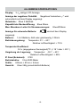
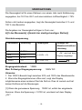
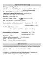
GENERAL SPECIFICATION
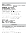
Display: 35/6digits LCD
Negative Polarity Indication: Negative sign "-" shown on the display
automatically
Sampling Rate: About 3 times/sec
Jaw Opening Capability: About 50mm
Max. Measurable Conductor for Current
Measurements: About Ø38mm
Low Battery Indication: " " shown on the display
Battery: 1.5V battery, AAA or equivalent, 3 pieces
Operating Environment: Temperature: 0℃~ 40℃
Relative Humidity: < 75%
Temperature Coefficient:
0.2 x (specified accuracy)/0C (< 18℃or > 28℃)
Storage Environment: Temperature: -30℃~ 60℃
Relative Humidity: < 85%
IP Degree: IP20
Operating Altitude: 0 to 2000 meters
Size: 243mm × 87mm × 44mm
Weight: About 382g ( including battery )
SPECIFICATION
Accuracy is specified for a period of one year after calibration and at 18°C
to 28°C, with relative humidity < 75%.
Except for the ranges specified specially, accuracy is specified from 5% of
range to 100% of range.
Accuracy specifications take the form of:
±([% of Reading] +[number of Least Significant Digits])

- 15 -
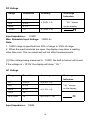
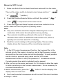
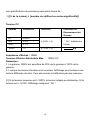
DC Voltage
Input Impedance: 10MΩ
Max. Allowable Input Voltage: 1000V dc
Note:
1. 1000V range is specified from 20% of range to 100% of range.
2. When the input terminals are open, the display may show a reading
other than zero. This is normal and will not affect measurements.
[1] If the voltage being measured is≥1000V, the built-in buzzer will sound.
If the voltage is > 1010V, the display will show " OL ".
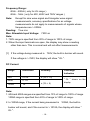
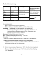
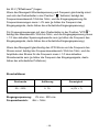
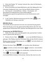
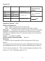
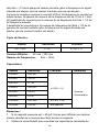
AC Voltage
Input Impedance: 10MΩ
Range Resolution Accuracy Overrange
Indication
6V 0.001V
± (0.8% + 5) " OL " shown
on the display
60V 0.01V
600V 0. 1V
1000V 1V ± (1.0% + 5)
Range Resolution Accuracy Overrange
Indication
6V 0.001V ± (0.8% + 5)
" OL " shown
on the display
60V 0.01V
± (1.2% + 5)
600V 0. 1V
750V 1V
VFD 750V 1V ± (2.5% + 15)

- 16 -
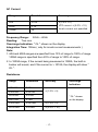
Frequency Range:
40Hz - 400Hz ( only for 6V range )
40Hz - 1kHz ( only for 60V, 600V and 750V ranges )
Note: Except for sine wave signal and triangular wave signal
measurements, accuracy specifications for ac voltage
measurements do not apply to measurements of signals whose
frequencies are > 200Hz.
Reading: True rms
Max. Allowable Input Voltage: 750V ac
Note:
1. 750V range is specified from 20% of range to 100% of range.
2. When the input terminals are open, the display may show a reading
other than zero. This is normal and will not affect measurements.
[1] If the voltage being measured is≥750V, the built-in buzzer will sound.
If the voltage is > 760V, the display will show " OL ".
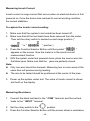
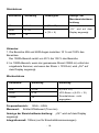
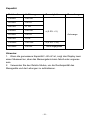
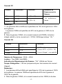
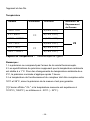
DC Current
Note:
1. 60A and 600A ranges are specified from 10% of range to 100% of range.
1000A range is specified from 20% of range to 100% of range.
2. In 1000A range, if the current being measured is≥1000A, the built-in
buzzer will sound, and if the current is > 1010A, the display will show "
OL ".
Range Resolution Accuracy Overrange
Indication
60A 0.01A ± (3% + 10)
" OL " shown on the
display
600A 0. 1A
± (3% + 6)
1000A 1A

- 17 -
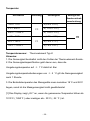
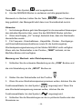
AC Current
Range Resolution Accuracy
60A 0.01A ± (2.5% + 6)
VFD current: ± (5.0% + 15)
Inrush current: not specified
600A 0.1A
1000A 1A
Frequency Range: 50Hz ~ 60Hz
Reading: True rms
Overrange Indication: " OL " shown on the display
Integration Time: 100ms ( only for inrush current measurements )
Note:
1. 60A and 600A ranges are specified from 10% of range to 100% of range.
1000A range is specified from 20% of range to 100% of range.
2. In 1000A range, if the current being measured is 1000A, the built-in
buzzer will sound, and if the current is > 1010A, the display will show "
OL ".
Resistance
Range Resolution Accuracy Overrange
Indication
600.0 Ω 0.1Ω
± (1.0% + 5)
" OL " shown
on the display
6.000 kΩ 0.001kΩ
60.00 kΩ 0.01kΩ
600.0 kΩ 0.1kΩ
6.000 MΩ 0.001MΩ ± (1.5% + 5)
60.00 MΩ 0.01MΩ ± (3.0% + 10)

- 18 -
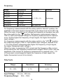
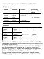
Frequency
Range Resolution Accuracy Remark
9.999Hz 0.001Hz
± ( 1.0% + 5) Autorange
99.99Hz 0.01Hz
999.9Hz 0.1Hz
9 999kHz 0 001kHz
99.99kHz 0.01kHz
999.9kHz 0. 1kHz
9.999MHz 0.001MHz not specified
For frequency measurements with the rotary switch in the"H%" position, the
amplitude of the input signal is required tobe in the range of 2V rms to 20V rms.
When the meter is measuring ac voltage and frequency at thesame time with
the rotary switch in the " " position, thefrequency measurement range is
10Hz to 1kHz and theinput voltage for frequency measurements is required
to be >2V(the higher the frequency of input signal, the higher therequired
input voltage ).
For frequency measurements with the rotary switch in the "VFD " position,
the measuring range is 10Hz to 1kHz,andthe input voltage is required to be
> 1/3 of the present voltagerange(the higher the frequency of input signal,
the higher therequired input voltage ).
When the meter is measuring VFD current and the freguency ofthe current
at the same time, the frequency measurement rangeis 10Hz to 1kHz, and the
amplitude of the current for frequency measurement is required to be > 1/3
of the present currentrange(the higher the frequency of input signal, the
higher therequired current to be tested ).
Duty Cycle
Range Resolution Accuracy
5% ~ 95% 0. 1% ±(2% + 7)
Input Voltage: 2V rms - 20V rms
Frequency Range: 4Hz ~ 1kHz

- 19 -
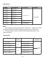
Capacitance
Range Resolution Accuracy Remark
6.000nF 0.001nF
± (5.0% + 5)
Autorange
60.00nF 0.01nF
600.0nF 0. 1nF
6.000uF 0.001uF
60.00uF 0.01uF
600.0uF 0.1uF
6.000mF 0.001mF ± (5.0% + 20)
60.00mF 0.01mF not specified
Note:
1. If the capacitance being measured is > 60mF, the display may show
a reading, but the measurement result may be wrong or inaccurate.
2. Use the Relative mode to subtract the residual capacitance of the
meter and leads.
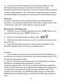
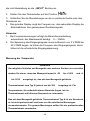
Temperature
Range Reso-
lution
Accuracy Overrange
Indication
- 20°C ~ 0°C
1°C
± (6.0% + 5°C)
0°C ~ 400°C ± ( 1.5% + 4°C)
400°C ~ 1000°C ± ( 1.8% + 5°C)
- 4°F ~ 32°F
1°F
± (6.0% + 9°F)
32°F ~ 752°F ± (1.5% + 7°F)
752°F ~ 1832°F ± (1.8% + 9°F)

- 20 -
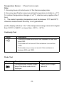
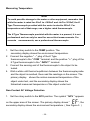
Temperature Sensor: K Type thermocouple
Note:
1. Accuracy does not include error of the thermocouple probe.
2. Accuracy specification assumes ambient temperature is stable to ± 1°C.
For ambient temperature changes of ± 5°C, rated accuracy applies after 1
hour.
3. The meter's operating temperature must be between 18°C and 28°C;
otherwise measurement accuracy is not guaranteed.
[1] The display will show " OL " if the temperature being measured is higher
than 1010°C ( 1850°F ) or lower than - 30°C ( - 22°F ).
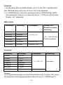
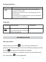
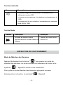
Continuity Test
Range Description
The built-in buzzer will sound if the resistance is less than
about 50Ω.
The buzzer will not sound if the resistance is more than
100Ω.
The buzzer may or may not sound if the resistance is
between 50Ω and 100Ω.
Diode Test
Range Description Remark
The approximate forward voltage
drop of the diode under test is
displayed.
Open Circuit Voltage:
about 4V
Seite wird geladen ...
Seite wird geladen ...
Seite wird geladen ...
Seite wird geladen ...
Seite wird geladen ...
Seite wird geladen ...
Seite wird geladen ...
Seite wird geladen ...
Seite wird geladen ...
Seite wird geladen ...
Seite wird geladen ...
Seite wird geladen ...
Seite wird geladen ...
Seite wird geladen ...
Seite wird geladen ...
Seite wird geladen ...
Seite wird geladen ...
Seite wird geladen ...
Seite wird geladen ...
Seite wird geladen ...
Seite wird geladen ...
Seite wird geladen ...
Seite wird geladen ...
Seite wird geladen ...
Seite wird geladen ...
Seite wird geladen ...
Seite wird geladen ...
Seite wird geladen ...
Seite wird geladen ...
Seite wird geladen ...
Seite wird geladen ...
Seite wird geladen ...
Seite wird geladen ...
Seite wird geladen ...
Seite wird geladen ...
Seite wird geladen ...
Seite wird geladen ...
Seite wird geladen ...
Seite wird geladen ...
Seite wird geladen ...
Seite wird geladen ...
Seite wird geladen ...
Seite wird geladen ...
Seite wird geladen ...
Seite wird geladen ...
Seite wird geladen ...
Seite wird geladen ...
Seite wird geladen ...
Seite wird geladen ...
Seite wird geladen ...
Seite wird geladen ...
Seite wird geladen ...
Seite wird geladen ...
Seite wird geladen ...
Seite wird geladen ...
Seite wird geladen ...
Seite wird geladen ...
Seite wird geladen ...
Seite wird geladen ...
Seite wird geladen ...
Seite wird geladen ...
Seite wird geladen ...
Seite wird geladen ...
Seite wird geladen ...
Seite wird geladen ...
Seite wird geladen ...
Seite wird geladen ...
Seite wird geladen ...
Seite wird geladen ...
Seite wird geladen ...
Seite wird geladen ...
Seite wird geladen ...
Seite wird geladen ...
Seite wird geladen ...
Seite wird geladen ...
Seite wird geladen ...
Seite wird geladen ...
Seite wird geladen ...
Seite wird geladen ...
Seite wird geladen ...
Seite wird geladen ...
Seite wird geladen ...
Seite wird geladen ...
Seite wird geladen ...
Seite wird geladen ...
Seite wird geladen ...
Seite wird geladen ...
Seite wird geladen ...
Seite wird geladen ...
Seite wird geladen ...
Seite wird geladen ...
Seite wird geladen ...
Seite wird geladen ...
Seite wird geladen ...
Seite wird geladen ...
Seite wird geladen ...
Seite wird geladen ...
Seite wird geladen ...
Seite wird geladen ...
Seite wird geladen ...
Seite wird geladen ...
Seite wird geladen ...
Seite wird geladen ...
Seite wird geladen ...
-
 1
1
-
 2
2
-
 3
3
-
 4
4
-
 5
5
-
 6
6
-
 7
7
-
 8
8
-
 9
9
-
 10
10
-
 11
11
-
 12
12
-
 13
13
-
 14
14
-
 15
15
-
 16
16
-
 17
17
-
 18
18
-
 19
19
-
 20
20
-
 21
21
-
 22
22
-
 23
23
-
 24
24
-
 25
25
-
 26
26
-
 27
27
-
 28
28
-
 29
29
-
 30
30
-
 31
31
-
 32
32
-
 33
33
-
 34
34
-
 35
35
-
 36
36
-
 37
37
-
 38
38
-
 39
39
-
 40
40
-
 41
41
-
 42
42
-
 43
43
-
 44
44
-
 45
45
-
 46
46
-
 47
47
-
 48
48
-
 49
49
-
 50
50
-
 51
51
-
 52
52
-
 53
53
-
 54
54
-
 55
55
-
 56
56
-
 57
57
-
 58
58
-
 59
59
-
 60
60
-
 61
61
-
 62
62
-
 63
63
-
 64
64
-
 65
65
-
 66
66
-
 67
67
-
 68
68
-
 69
69
-
 70
70
-
 71
71
-
 72
72
-
 73
73
-
 74
74
-
 75
75
-
 76
76
-
 77
77
-
 78
78
-
 79
79
-
 80
80
-
 81
81
-
 82
82
-
 83
83
-
 84
84
-
 85
85
-
 86
86
-
 87
87
-
 88
88
-
 89
89
-
 90
90
-
 91
91
-
 92
92
-
 93
93
-
 94
94
-
 95
95
-
 96
96
-
 97
97
-
 98
98
-
 99
99
-
 100
100
-
 101
101
-
 102
102
-
 103
103
-
 104
104
-
 105
105
-
 106
106
-
 107
107
-
 108
108
-
 109
109
-
 110
110
-
 111
111
-
 112
112
-
 113
113
-
 114
114
-
 115
115
-
 116
116
-
 117
117
-
 118
118
-
 119
119
-
 120
120
-
 121
121
-
 122
122
-
 123
123
-
 124
124


VEVOR EM4659 Benutzerhandbuch
- Kategorie
- Messen, Testen
- Typ
- Benutzerhandbuch
in anderen Sprachen
- English: VEVOR EM4659 User manual
- français: VEVOR EM4659 Manuel utilisateur
Andere Dokumente
-
METREL MD 9250 Benutzerhandbuch
-
Amprobe ACD-3300 & ACD-3400 Industrial Clamp Meters Benutzerhandbuch
-
-
Sonel CMP-1015-PV Benutzerhandbuch
-
Wavetek 2015 Bedienungsanleitung
-
 Wavetek Meterman 235 Bedienungsanleitung
-
-
B&K 2704C Benutzerhandbuch
-
-
CHAUVIN ARNOUX PAC 12 CVH Benutzerhandbuch
